Performing Initial Software Configuration on an NFX250 Device
Before you begin connecting and configuring an NFX250 device, set the following parameter values on the console server or PC:
Baud Rate—9600
Flow Control—None
Data—8
Parity—None
Stop Bits—1
DCD State—Disregard
You must perform the initial configuration of the device through the console port using the Juniper Device Manager (JDM) command-line interface (CLI).
To connect and configure the device from the console:
If Network Service Orchestrator module is configured, this client connects to the Network Activator as soon as the device is switched on, and provisions the initial configuration and the latest software image and, if the image on the device is not the latest.
Network Activator is responsible for the bare-minimum bootstrapping of the device. After successful configuration and software upgrade, the device reboots and the Network Activator configuration is removed.
To complete the configuration of the Network Service Orchestrator module process:
Connect to any front panel WAN port (see Figure 2).
Open web browser and enter the IP address 10.10.10.1.
Enter the authentication code in the Web page that is displayed.
Figure 1: Network Service Orchestrator module
Once the process is complete, a confirmation message is displayed. Click Logs to display details of the bootstrapping process. Refer to Captive Portal Log Messages for the list of log messages that are displayed.
Note:You can also use the CLI to provide the authentication code:
root@jdm> test phone-home server-authentication-code code
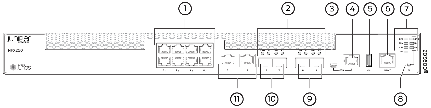
1 — 1-Gigabit Ethernet RJ-45 network ports | 7 — System status LEDs |
2 — SFP and SFP+ ports Link and Status LEDs | 8 — Mode button |
3 — mini-USB console port | 9 — 1/10-Gigabit SFP+ uplink ports |
4 — Console port | 10 — 1-Gigabit SFP network/uplink ports |
5 — USB port | 11 — 1-Gigabit Ethernet RJ-45 network/uplink ports |
6 — 1-Gigabit Management port |