Examples: Configuring PIM RPT and SPT Cutover
Building an RPT Between the RP and Receivers
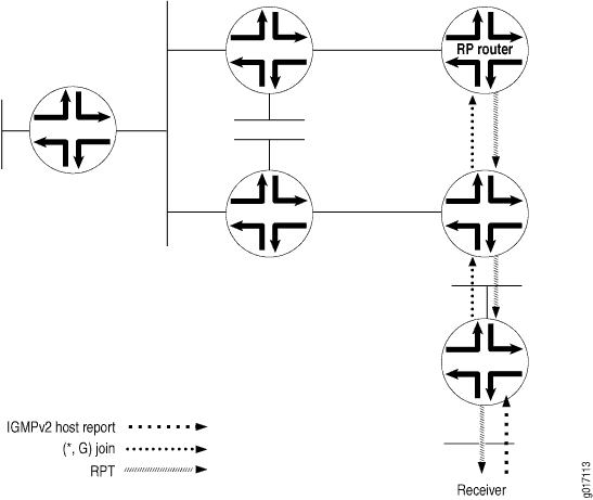
The RPT is the path between the RP and receivers (hosts) in a multicast group (see Figure 1). The RPT is built by means of a PIM join message from a receiver's DR:
-
A receiver sends a request to join group (G) in an Internet Group Management Protocol (IGMP) host membership report. A PIM sparse-mode router, the receiver’s DR, receives the report on a directly attached subnet and creates an RPT branch for the multicast group of interest.
-
The receiver’s DR sends a PIM join message to its RPF neighbor, the next-hop address in the RPF table, or the unicast routing table.
-
The PIM join message travels up the tree and is multicast to the ALL-PIM-ROUTERS group (224.0.0.13). Each router in the tree finds its RPF neighbor by using either the RPF table or the unicast routing table. This is done until the message reaches the RP and forms the RPT. Routers along the path set up the multicast forwarding state to forward requested multicast traffic back down the RPT to the receiver.
PIM Sparse Mode Source Registration
The RPT is a unidirectional tree, permitting traffic to flow down from the RP to the receiver in one direction. For multicast traffic to reach the receiver from the source, another branch of the distribution tree, called the shortest-path tree, needs to be built from the source's DR to the RP.
The shortest-path tree is created in the following way:
-
The source becomes active, sending out multicast packets on the LAN to which it is attached. The source’s DR receives the packets and encapsulates them in a PIM register message, which it sends to the RP router (see Figure 2).
-
When the RP router receives the PIM register message from the source, it sends a PIM join message back to the source.
Figure 2: PIM Register Message and PIM Join Message Exchanged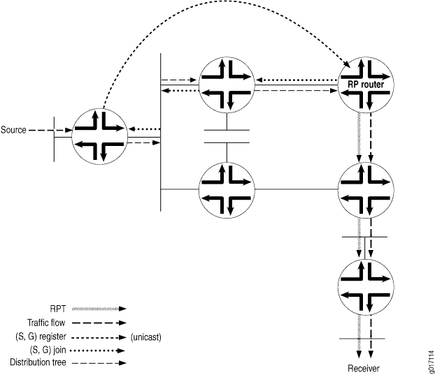
-
The source’s DR receives the PIM join message and begins sending traffic down the SPT toward the RP router (see Figure 3).
-
Once traffic is received by the RP router, it sends a register stop message to the source’s DR to stop the register process.
Figure 3: Traffic Sent from the Source to the RP Router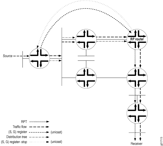
-
The RP router sends the multicast traffic down the RPT toward the receiver (see Figure 4).
Figure 4: Traffic Sent from the RP Router Toward the Receiver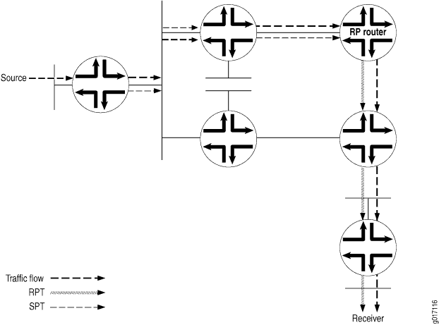
Multicast Shortest-Path Tree
The distribution tree used for multicast is rooted at the source and is the shortest-path tree (SPT) as well. Consider a set of multicast routers without any active multicast traffic for a certain group (that is, they have no multicast forwarding state for that group). When a router learns that an interested receiver for that group is on one of its directly connected subnets, the router attempts to join the tree for that group.
To join the distribution tree, the router determines the unicast IP address of the source for that group. This address can be a simple static configuration on the router, or as complex as a set of protocols.
To build the SPT for that group, the router executes an a reverse path forwarding (RPF) check on the source address in its routing table. The RPF check produces the interface closest to the source, which is where multicast packets from this source for this group need to flow into the router.
The router next sends a join message out on this interface using the proper multicast protocol to inform the upstream router that it wants to join the distribution tree for that group. This message is an (S,G) join message because both S and G are known. The router receiving the (S,G) join message adds the interface on which the message was received to its output interface list (OIL) for the group and also performs an RPF check on the source address. The upstream router then sends an (S,G) join message out on the RPF interface toward the source, informing the upstream router that it also wants to join the group.
Each upstream router repeats this process, propagating joins out on the RPF interface, building the SPT as it goes. The process stops when the join message does one of two things:
Reaches the router directly connected to the host that is the source.
Reaches a router that already has multicast forwarding state for this source-group pair.
In either case, the branch is created, each of the routers has multicast forwarding state for the source-group pair, and packets can flow down the distribution tree from source to receiver. The RPF check at each router makes sure that the tree is an SPT.
SPTs are always the shortest path, but they are not necessarily short. That is, sources and receivers tend to be on the periphery of a router network, not on the backbone, and multicast distribution trees have a tendency to sprawl across almost every router in the network. Because multicast traffic can overwhelm a slow interface, and one packet can easily become a hundred or a thousand on the opposite side of the backbone, it makes sense to provide a shared tree as a distribution tree so that the multicast source can be located more centrally in the network, on the backbone. This sharing of distribution trees with roots in the core network is accomplished by a multicast rendezvous point. For more information about RPs, see Understanding Multicast Rendezvous Points, Shared Trees, and Rendezvous-Point Trees.
SPT Cutover
Instead of continuing to use the SPT to the RP and the RPT toward the receiver, a direct SPT is created between the source and the receiver in the following way:
-
Once the receiver’s DR receives the first multicast packet from the source, the DR sends a PIM join message to its RPF neighbor (see Figure 5).
-
The source’s DR receives the PIM join message, and an additional (S,G) state is created to form the SPT.
-
Multicast packets from that particular source begin coming from the source's DR and flowing down the new SPT to the receiver’s DR. The receiver’s DR is now receiving two copies of each multicast packet sent by the source—one from the RPT and one from the new SPT.
Figure 5: Receiver DR Sends a PIM Join Message to the Source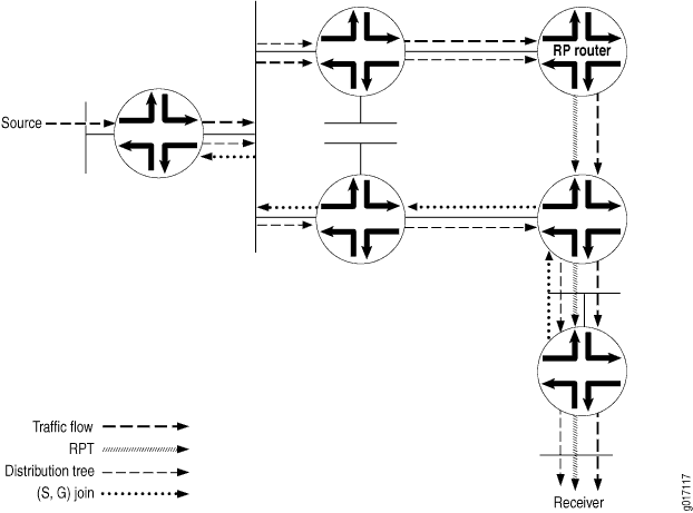
-
To stop duplicate multicast packets, the receiver’s DR sends a PIM prune message toward the RP router, letting it know that the multicast packets from this particular source coming in from the RPT are no longer needed (see Figure 6).
Figure 6: PIM Prune Message Is Sent from the Receiver’s DR Toward the RP Router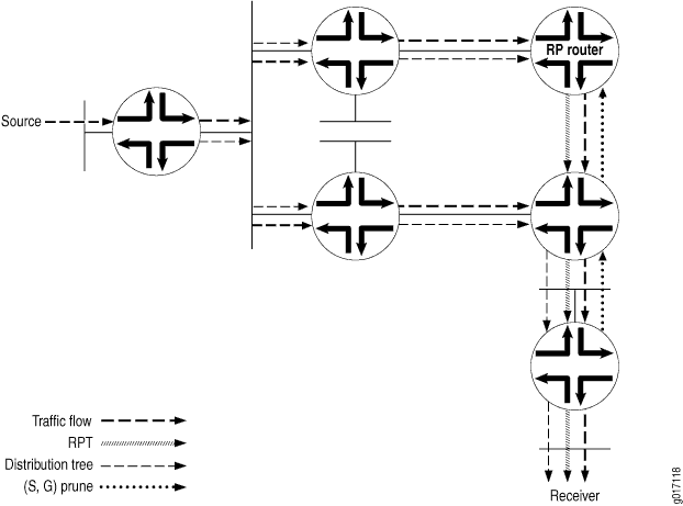
-
The PIM prune message is received by the RP router, and it stops sending multicast packets down to the receiver’s DR. The receiver’s DR is getting multicast packets only for this particular source over the new SPT. However, multicast packets from the source are still arriving from the source’s DR toward the RP router (see Figure 7).
Figure 7: RP Router Receives PIM Prune Message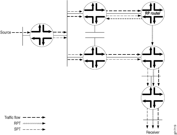
-
To stop the unneeded multicast packets from this particular source, the RP router sends a PIM prune message to the source’s DR (see Figure 8).
Figure 8: RP Router Sends a PIM Prune Message to the Source DR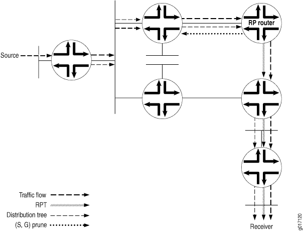
-
The receiver’s DR now receives multicast packets only for the particular source from the SPT (see Figure 9).
Figure 9: Source’s DR Stops Sending Duplicate Multicast Packets Toward the RP Router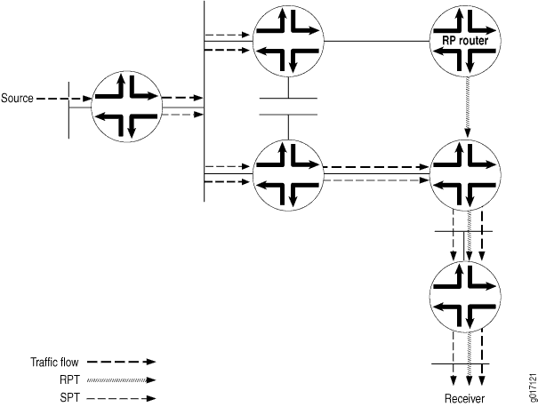
SPT Cutover Control
In some cases, the last-hop router needs to stay on the shared tree to the RP and not transition to a direct SPT to the source. You might not want the last-hop router to transition when, for example, a low-bandwidth multicast stream is forwarded from the RP to a last-hop router. All routers between last hop and source must maintain and refresh the SPT state. This can become a resource-intensive activity that does not add much to the network efficiency for a particular pair of source and multicast group addresses.
In these cases, you configure an SPT threshold policy on the last-hop router to control the transition to a direct SPT. An SPT cutover threshold of infinity applied to a source-group address pair means the last-hop router will never transition to a direct SPT. For all other source-group address pairs, the last-hop router transitions immediately to a direct SPT rooted at the source DR.
Example: Configuring the PIM Assert Timeout
This example shows how to configure the timeout period for a PIM assert forwarder.
Requirements
Before you begin:
Configure the router interfaces.
Configure an interior gateway protocol or static routing. See the Junos OS Routing Protocols Library for Routing Devices.
Configure PIM Sparse Mode on the interfaces. See Enabling PIM Sparse Mode.
Overview
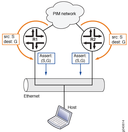
The role of PIM assert messages is to determine the forwarder on a network with multiple routers. The forwarder is the router that forwards multicast packets to a network with multicast group members. The forwarder is generally the same as the PIM DR.
A router sends an assert message when it receives a multicast packet on an interface that is listed in the outgoing interface list of the matching routing entry. Receiving a message on an outgoing interface is an indication that more than one router forwards the same multicast packets to a network.
In Figure 10, both routing devices R1 and R2 forward multicast packets for the same (S,G) entry on a network. Both devices detect this situation and both devices send assert messages on the Ethernet network. An assert message contains, in addition to a source address and group address, a unicast cost metric for sending packets to the source, and a preference metric for the unicast cost. The preference metric expresses a preference between unicast routing protocols. The routing device with the smallest preference metric becomes the forwarder (also called the assert winner). If the preference metrics are equal, the device that sent the lowest unicast cost metric becomes the forwarder. If the unicast metrics are also equal, the routing device with the highest IP address becomes the forwarder. After the transmission of assert messages, only the forwarder continues to forward messages on the network.
When an assert message is received and the RPF neighbor is changed to the assert winner, the assert timer is set to an assert timeout period. The assert timeout period is restarted every time a subsequent assert message for the route entry is received on the incoming interface. When the assert timer expires, the routing device resets its RPF neighbor according to its unicast routing table. Then, if multiple forwarders still exist, the forwarders reenter the assert message cycle. In effect, the assert timeout period determines how often multicast routing devices enter a PIM assert message cycle.
The range is from 5 through 210 seconds. The default is 180 seconds.
Assert messages are useful for LANs that connect multiple routing devices and no hosts.
Configuration
Procedure
Step-by-Step Procedure
The following example requires you to navigate various levels in the configuration hierarchy. For information about navigating the CLI, see Using the CLI Editor in Configuration Mode in the Junos OS CLI User Guide.
To configure an assert timeout:
Configure the timeout period, in seconds.
[edit protocols pim]
user@host# set assert-timeout 60
(Optional) Trace assert messages.
[edit protocols pim]
user@host# set traceoptions file PIM.log
user@host# set traceoptions flag assert detail
If you are done configuring the device, commit the configuration.
user@host# commit
To verify the configuration, run the following commands:
show pim join
show pim statistics
Example: Configuring the PIM SPT Threshold Policy
This example shows how to apply a policy that suppresses the transition from the rendezvous-point tree (RPT) rooted at the RP to the shortest-path tree (SPT) rooted at the source.
Requirements
Before you begin:
Configure the router interfaces.
Configure an interior gateway protocol or static routing. See the Junos OS Routing Protocols Library for Routing Devices.
Configure PIM Sparse Mode on the interfaces. See Enabling PIM Sparse Mode.
Overview
Multicast routing devices running PIM sparse mode can forward the same stream of multicast packets onto the same LAN through an RPT rooted at the RP or through an SPT rooted at the source. In some cases, the last-hop routing device needs to stay on the shared RPT to the RP and not transition to a direct SPT to the source. Receiving the multicast data traffic on SPT is optimal but introduces more state in the network, which might not be desirable in some multicast deployments. Ideally, low-bandwidth multicast streams can be forwarded on the RPT, and high-bandwidth streams can use the SPT. This example shows how to configure such a policy.
This example includes the following settings:
-
spt-threshold—Enables you to configure an SPT threshold policy on the last-hop routing device to control the transition to a direct SPT. When you include this statement in the main PIM instance, the PE router stays on the RPT for control traffic.
-
infinity—Applies an SPT cutover threshold of infinity to a source-group address pair, so that the last-hop routing device never transitions to a direct SPT. For all other source-group address pairs, the last-hop routing device transitions immediately to a direct SPT rooted at the source DR. This statement must reference a properly configured policy to set the SPT cutover threshold for a particular source-group pair to infinity. The use of values other than infinity for the SPT threshold is not supported. You can configure more than one policy.
-
policy-statement—Configures the policy. The simplest type of SPT threshold policy uses a route filter and source address filter to specify the multicast group and source addresses and to set the SPT threshold for that pair of addresses to infinity. The policy is applied to the main PIM instance.
This example sets the SPT transition value for the source-group pair 10.10.10.1 and 224.1.1.1 to infinity. When the policy is applied to the last-hop router, multicast traffic from this source-group pair never transitions to a direct SPT to the source. Traffic will continue to arrive through the RP. However, traffic for any other source-group address combination at this router transitions to a direct SPT to the source.
Note these points when configuring the SPT threshold policy:
-
Configuration changes to the SPT threshold policy affect how the routing device handles the SPT transition.
-
When the policy is configured for the first time, the routing device continues to transition to the direct SPT for the source-group address pair until the PIM-join state is cleared with the clear pim join command.
-
If you do not clear the PIM-join state when you apply the infinity policy configuration for the first time, you must apply it before the PE router is brought up.
-
When the policy is deleted for a source-group address pair for the first time, the routing device does not transition to the direct SPT for that source-group address pair until the PIM-join state is cleared with the clear pim join command.
-
When the policy is changed for a source-group address pair for the first time, the routing device does not use the new policy until the PIM-join state is cleared with the clear pim join command.
Topology
Configuration
Procedure
CLI Quick Configuration
To quickly configure this example, copy the
following commands, paste them into a text file, remove any line breaks,
change any details necessary to match your network configuration,
copy and paste the commands into the CLI at the [edit] hierarchy
level, and then enter commit from configuration mode.
[edit]
set policy-options policy-statement spt-infinity-policy term one from route-filter 224.1.1.1/32 exact
set policy-options policy-statement spt-infinity-policy term one from source-address-filter 10.10.10.1/32 exact
set policy-options policy-statement spt-infinity-policy term one then accept
set policy-options policy-statement spt-infinity-policy term two then reject
set protocols pim spt-threshold infinity spt-infinity-policy
Step-by-Step Procedure
The following example requires you to navigate various levels in the configuration hierarchy. For information about navigating the CLI, see the Junos OS CLI User Guide.
To configure an SPT threshold policy:
Apply the policy.
[edit]
user@host# edit protocols pim
[edit protocols pim]
user@host# set spt-threshold infinity spt-infinity-policy
[edit protocols pim]
user@host# exit
Configure the policy.
[edit]
user@host# edit policy-options policy-statement spt-infinity-policy
[edit policy-options policy-statement spt-infinity-policy]
user@host# set term one from route-filter 224.1.1.1/32 exact
[edit policy-options policy-statement spt-infinity-policy]
user@host# set term one from source-address-filter 10.10.10.1/32 exact
[edit policy-options policy-statement spt-infinity-policy]
user@host# set term one then accept
[edit policy-options policy-statement spt-infinity-policy]
user@host# set term two then reject
[edit policy-options policy-statement spt-infinity-policy]
user@host# exit
policy-statement {
If you are done configuring the device, commit the configuration.
[edit]
user@host# commit
Clear the PIM join cache to force the configuration to take effect.
[edit]
user@host# run clear pim join
Results
Confirm your configuration by entering the show policy-options command and the show protocols command from configuration mode. If the output does not display the intended configuration, repeat the instructions in this example to correct the configuration.
user@host# show policy-options
policy-statement spt-infinity-policy {
    term one {
        from {
            route-filter 224.1.1.1/32 exact;
            source-address-filter 10.10.10.1/32 exact;
        }
        then accept;
    }
    term two {
        then reject;
    }
}
user@host# show protocols
pim {
    spt-threshold {
        infinity spt-infinity-policy;
    }
}
Verification
To verify the configuration, run the show pim join command.

