ON THIS PAGE
Example: Configuring IGMP Snooping
Understanding Multicast Snooping
Network devices such as routers operate mainly at the packet level, or Layer 3. Other network devices such as bridges or LAN switches operate mainly at the frame level, or Layer 2. Multicasting functions mainly at the packet level, Layer 3, but there is a way to map Layer 3 IP multicast group addresses to Layer 2 MAC multicast group addresses at the frame level.
Routers can handle both Layer 2 and Layer 3 addressing information because the frame and its addresses must be processed to access the encapsulated packet inside. Routers can run Layer 3 multicast protocols such as PIM or IGMP and determine where to forward multicast content or when a host on an interface joins or leaves a group. However, bridges and LAN switches, as Layer 2 devices, are not supposed to have access to the multicast information inside the packets that their frames carry.
How then are bridges and other Layer 2 devices to determine when a device on an interface joins or leaves a multicast tree, or whether a host on an attached LAN wants to receive the content of a particular multicast group?
The answer is for the Layer 2 device to implement multicast snooping. Multicast snooping is a general term and applies to the process of a Layer 2 device “snooping” at the Layer 3 packet content to determine which actions are taken to process or forward a frame. There are more specific forms of snooping, such as IGMP snooping or PIM snooping. In all cases, snooping involves a device configured to function at Layer 2 having access to normally “forbidden” Layer 3 (packet) information. Snooping makes multicasting more efficient in these devices.
See Also
Understanding IGMP Snooping
Snooping is a general way for Layer 2 devices, such as Juniper Networks MX Series Ethernet Services Routers, to implement a series of procedures to “snoop” at the Layer 3 packet content to determine which actions are to be taken to process or forward a frame. More specific forms of snooping, such as Internet Group Membership Protocol (IGMP ) snooping or Protocol Independent Multicast (PIM) snooping, are used with multicast.
Layer 2 devices (LAN switches or bridges) handle multicast packets and the frames that contain them much in the same way the Layer 3 devices (routers) handle broadcasts. So, a Layer 2 switch processes an arriving frame having a multicast destination media access control (MAC) address by forwarding a copy of the packet (frame) onto each of the other network interfaces of the switch that are in a forwarding state.
However, this approach (sending multicast frames everywhere the device can) is not the most efficient use of network bandwidth, particularly for IPTV applications. IGMP snooping functions by “snooping” at the IGMP packets received by the switch interfaces and building a multicast database similar to that a multicast router builds in a Layer 3 network. Using this database, the switch can forward multicast traffic only onto downstream interfaces with interested receivers, and this technique allows more efficient use of network bandwidth.
You configure IGMP snooping for each bridge on the router. A bridge instance without qualified learning has just one learning domain. For a bridge instance with qualified learning, snooping will function separately within each learning domain in the bridge. That is, IGMP snooping and multicast forwarding will proceed independently in each learning domain in the bridge.
This discussion focuses on bridge instances without qualified learning (those forming one learning domain on the device). Therefore, all the interfaces mentioned are logical interfaces of the bridge or VPLS instance.
Several related concepts are important when discussing IGMP snooping:
Bridge or VPLS instance interfaces are either multicast-router interfaces or host-side interfaces.
IGMP snooping supports proxy mode or without-proxy mode.
When integrated routing and bridging (IRB) is used, if the router is an IGMP querier, any leave message received on any Layer 2 interface will cause a group-specific query on all Layer 2 interfaces (as a result of this practice, some corresponding reports might be received on all Layer 2 interfaces). However, if some of the Layer 2 interfaces are also router (Layer 3) interfaces, reports and leaves from other Layer 2 interfaces will not be forwarded on those interfaces.
If an IRB interface is used as an outgoing interface in a multicast forwarding cache entry (as determined by the routing process), then the output interface list is expanded into a subset of the Layer 2 interface in the corresponding bridge. The subset is based on the snooped multicast membership information, according to the multicast forwarding cache entry installed by the snooping process for the bridge.
If no snooping is configured, the IRB output interface list is expanded to all Layer 2 interfaces in the bridge.
The Junos OS does not support IGMP snooping in a VPLS configuration on a virtual switch. This configuration is disallowed in the CLI.
See Also
IGMP Snooping Interfaces and Forwarding
IGMP snooping divides the device interfaces into multicast-router interfaces and host-side interfaces. A multicast-router interface is an interface in the direction of a multicasting router. An interface on the bridge is considered a multicast-router interface if it meets at least one of the following criteria:
It is statically configured as a multicast-router interface in the bridge instance.
IGMP queries are being received on the interface.
All other interfaces that are not multicast-router interfaces are considered host-side interfaces.
Any multicast traffic received on a bridge interface with IGMP snooping configured will be forwarded according to following rules:
Any IGMP packet is sent to the Routing Engine for snooping processing.
Other multicast traffic with destination address 224.0.0/24 is flooded onto all other interfaces of the bridge.
Other multicast traffic is sent to all the multicast-router interfaces but only to those host-side interfaces that have hosts interested in receiving that multicast group.
See Also
IGMP Snooping and Proxies
Without a proxy arrangement, IGMP snooping does not generate or introduce queries and reports. It will only “snoop” reports received from all of its interfaces (including multicast-router interfaces) to build its state and group (S,G) database.
Without a proxy, IGMP messages are processed as follows:
Query—All general and group-specific IGMP query messages received on a multicast-router interface are forwarded to all other interfaces (both multicast-router interfaces and host-side interfaces) on the bridge.
Report—IGMP reports received on any interface of the bridge are forwarded toward other multicast-router interfaces. The receiving interface is added as an interface for that group if a multicast routing entry exists for this group. Also, a group timer is set for the group on that interface. If this timer expires (that is, there was no report for this group during the IGMP group timer period), then the interface is removed as an interface for that group.
Leave—IGMP leave messages received on any interface of the bridge are forwarded toward other multicast-router interfaces on the bridge. The Leave Group message reduces the time it takes for the multicast router to stop forwarding multicast traffic when there are no longer any members in the host group.
Proxy snooping reduces the number of IGMP reports sent toward an IGMP router.
With proxy snooping configured, an IGMP router is not able to perform host tracking.
As proxy for its host-side interfaces, IGMP snooping in proxy mode replies to the queries it receives from an IGMP router on a multicast-router interface. On the host-side interfaces, IGMP snooping in proxy mode behaves as an IGMP router and sends general and group-specific queries on those interfaces.
Only group-specific queries are generated by IGMP snooping directly. General queries received from the multicast-router interfaces are flooded to host-side interfaces.
All the queries generated by IGMP snooping are sent using 0.0.0.0 as the source address. Also, all reports generated by IGMP snooping are sent with 0.0.0.0 as the source address unless there is a configured source address to use.
Proxy mode functions differently on multicast-router interfaces than it does on host-side interfaces.
See Also
Multicast-Router Interfaces and IGMP Snooping Proxy Mode
On multicast-router interfaces, in response to IGMP queries, IGMP snooping in proxy mode sends reports containing aggregate information on groups learned on all host-side interfaces of the bridge.
Besides replying to queries, IGMP snooping in proxy mode forwards all queries, reports, and leaves received on a multicast-router interface to other multicast-router interfaces. IGMP snooping keeps the membership information learned on this interface but does not send a group-specific query for leave messages received on this interface. It simply times out the groups learned on this interface if there are no reports for the same group within the timer duration.
For the hosts on all the multicast-router interfaces, it is the IGMP router, not the IGMP snooping proxy, that generates general and group-specific queries.
See Also
Host-Side Interfaces and IGMP Snooping Proxy Mode
No reports are sent on host-side interfaces by IGMP snooping in proxy mode. IGMP snooping processes reports received on these interfaces and sends group-specific queries onto host-side interfaces when it receives a leave message on the interface. Host-side interfaces do not generate periodic general queries, but forwards or floods general queries received from multicast-router interfaces.
If a group is removed from a host-side interface and this was the last host-side interface for that group, a leave is sent to the multicast-router interfaces. If a group report is received on a host-side interface and this was the first host-side interface for that group, a report is sent to all multicast-router interfaces.
See Also
IGMP Snooping and Bridge Domains
IGMP snooping on a VLAN is only allowed for the legacy vlan-id all case. In other cases, there is a specific bridge domain configuration that determines the VLAN-specific configuration for IGMP snooping.
See Also
Configuring IGMP Snooping
To configure Internet Group Management Protocol (IGMP) snooping, include the igmp-snooping statement:
igmp-snooping {
    immediate-leave;
    interface interface-name {
        group-limit limit;
        host-only-interface;
        immediate-leave;
        multicast-router-interface;
        static {
            group ip-address {
                source ip-address;
            }
        }
    }
    proxy {
        source-address ip-address;
    }
    query-interval seconds;
    query-last-member-interval seconds;
    query-response-interval seconds;
    robust-count number;
    vlan vlan-id {
        immediate-leave;
        interface interface-name {
            group-limit limit;
            host-only-interface;
            immediate-leave;
            multicast-router-interface;
            static {
                group ip-address {
                    source ip-address;
                }
            }
        }
        proxy {
            source-address ip-address;
        }
        query-interval seconds;
        query-last-member-interval seconds;
        query-response-interval seconds;
        robust-count number;
    }
}
You can include this statement at the following hierarchy levels:
[edit bridge-domains bridge-domain-name protocols]
[edit routing-instances routing-instance-name bridge-domains bridge-domain-name protocols]
By default, IGMP snooping is not enabled. Statements configured at the VLAN level apply only to that particular VLAN.
See Also
Configuring VLAN-Specific IGMP Snooping Parameters
All of the IGMP snooping statements configured with the igmp-snooping statement,
with the exception of the traceoptions statement, can be qualified with the same
statement at the VLAN level. To configure IGMP snooping parameters at the VLAN level, include
the vlan statement:
vlan vlan-id;
    immediate-leave;
    interface interface-name {
        group-limit limit;
        host-only-interface;
        multicast-router-interface;
        static {
            group ip-address {
                source ip-address;
            }
        }
    }
    proxy {
        source-address ip-address;
    }
    query-interval seconds;
    query-last-member-interval seconds;
    query-response-interval seconds;
    robust-count number;
}
You can include this statement at the following hierarchy levels:
[edit bridge-domains bridge-domain-name protocols igmp-snooping][edit routing-instances routing-instance-name bridge-domains bridge-domain-name protocols igmp-snooping]
See Also
Example: Configuring IGMP Snooping
This example shows how to configure IGMP snooping. IGMP snooping can reduce unnecessary traffic from IP multicast applications.
Requirements
This example uses the following hardware components:
One MX Series router
One Layer 3 device functioning as a multicast router
Before you begin:
Configure the interfaces. See the Interfaces User Guide for Security Devices.
Configure an interior gateway protocol. See the Junos OS Routing Protocols Library for Routing Devices.
Configure a multicast protocol. This feature works with the following multicast protocols:
DVMRP
PIM-DM
PIM-SM
PIM-SSM
Overview and Topology
IGMP snooping controls multicast traffic in a switched network. When IGMP snooping is not enabled, the Layer 2 device broadcasts multicast traffic out of all of its ports, even if the hosts on the network do not want the multicast traffic. With IGMP snooping enabled, a Layer 2 device monitors the IGMP join and leave messages sent from each connected host to a multicast router. This enables the Layer 2 device to keep track of the multicast groups and associated member ports. The Layer 2 device uses this information to make intelligent decisions and to forward multicast traffic to only the intended destination hosts.
This example includes the following statements:
proxy—Enables the Layer 2 device to actively filter IGMP packets to reduce load on the multicast router. Joins and leaves heading upstream to the multicast router are filtered so that the multicast router has a single entry for the group, regardless of how many active listeners have joined the group. When a listener leaves a group but other listeners remain in the group, the leave message is filtered because the multicast router does not need this information. The status of the group remains the same from the router's point of view.
immediate-leave—When only one IGMP host is connected, the
immediate-leavestatement enables the multicast router to immediately remove the group membership from the interface and suppress the sending of any group-specific queries for the multicast group.When you configure this feature on IGMPv2 interfaces, ensure that the IGMP interface has only one IGMP host connected. If more than one IGMPv2 host is connected to a LAN through the same interface, and one host sends a leave message, the router removes all hosts on the interface from the multicast group. The router loses contact with the hosts that properly remain in the multicast group until they send join requests in response to the next general multicast listener query from the router.
When IGMP snooping is enabled on a router running IGMP version 3 (IGMPv3) snooping, after the router receives a report with the type BLOCK_OLD_SOURCES, the router suppresses the sending of group-and-source queries but relies on the Junos OS host-tracking mechanism to determine whether or not it removes a particular source group membership from the interface.
query-interval—Enables you to change the number of IGMP messages sent on the subnet by configuring the interval at which the IGMP querier router sends general host-query messages to solicit membership information.
By default, the query interval is 125 seconds. You can configure any value in the range 1 through 1024 seconds.
query-last-member-interval—Enables you to change the amount of time it takes a device to detect the loss of the last member of a group.
The last-member query interval is the maximum amount of time between group-specific query messages, including those sent in response to leave-group messages.
By default, the last-member query interval is 1 second. You can configure any value in the range 0.1 through 0.9 seconds, and then 1-second intervals from 1 through 1024 seconds.
query-response-interval—Configures how long the router waits to receive a response from its host-query messages.
By default, the query response interval is 10 seconds. You can configure any value in the range 1 through 1024 seconds. This interval should be less than the interval set in the
query-intervalstatement.robust-count—Provides fine-tuning to allow for expected packet loss on a subnet. It is basically the number of intervals to wait before timing out a group. You can wait more intervals if subnet packet loss is high and IGMP report messages might be lost.
By default, the robust count is 2. You can configure any value in the range 2 through 10 intervals.
group-limit—Configures a limit for the number of multicast groups (or [S,G] channels in IGMPv3) that can join an interface. After this limit is reached, new reports are ignored and all related flows are discarded, not flooded.
By default, there is no limit to the number of groups that can join an interface. You can configure a limit in the range 0 through a 32-bit number.
host-only-interface—Configure an IGMP snooping interface to be an exclusively host-side interface. On a host-side interface, received IGMP queries are dropped.
By default, an interface can face either other multicast routers or hosts.
multicast-router-interface—Configures an IGMP snooping interface to be an exclusively router-facing interface.
By default, an interface can face either other multicast routers or hosts.
static—Configures an IGMP snooping interface with multicast groups statically.
By default, the router learns about multicast groups on the interface dynamically.
Topology
Figure 1 shows networks without IGMP snooping. Suppose host A is an IP multicast sender and hosts B and C are multicast receivers. The router forwards IP multicast traffic only to those segments with registered receivers (hosts B and C). However, the Layer 2 devices flood the traffic to all hosts on all interfaces.
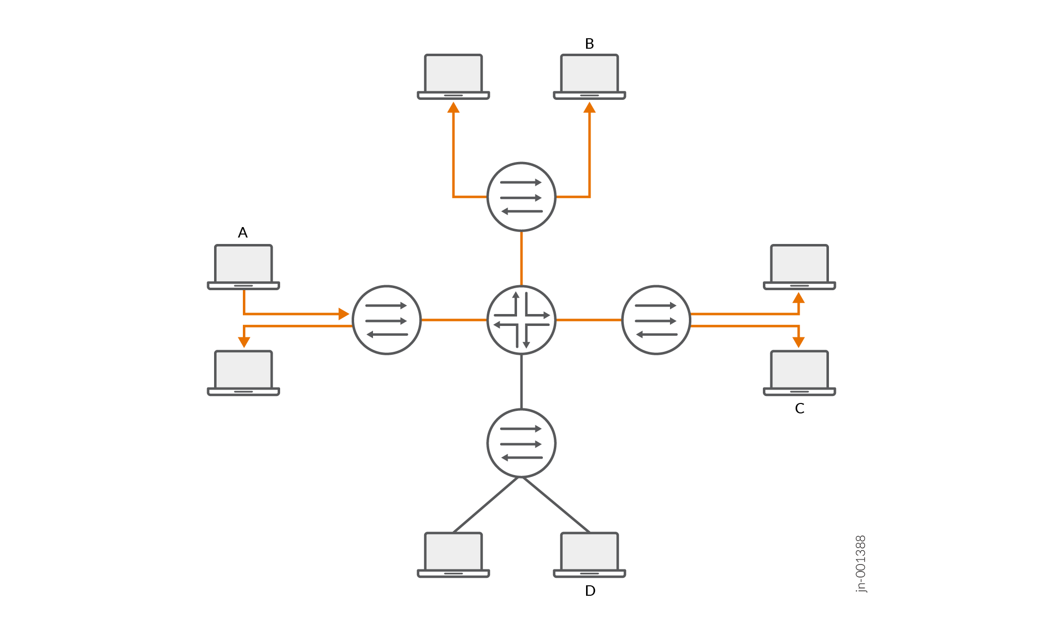
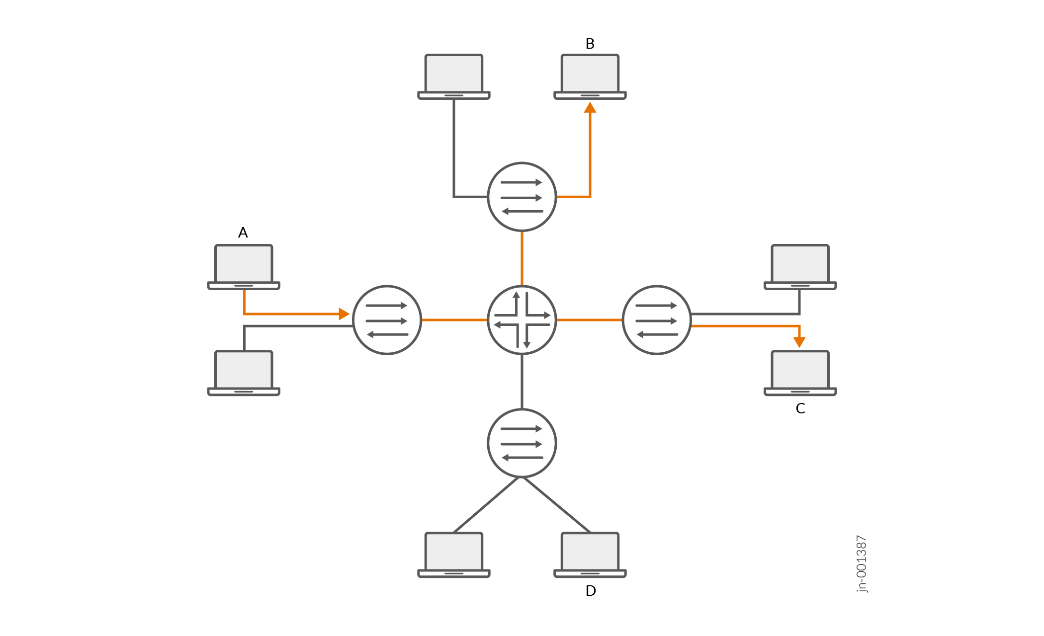
Figure 2 shows the same networks with IGMP snooping configured. The Layer 2 devices forward multicast traffic to registered receivers only.
Configuration
Procedure
CLI Quick Configuration
To quickly configure this example, copy the
following commands, paste them into a text file, remove any line breaks,
change any details necessary to match your network configuration,
copy and paste the commands into the CLI at the [edit] hierarchy
level, and then enter commit from configuration mode.
set bridge-domains domain1 domain-type bridge
set bridge-domains domain1 interface ge-0/0/1.1
set bridge-domains domain1 interface ge-0/0/2.1
set bridge-domains domain1 interface ge-0/0/3.1
set bridge-domains domain1 protocols igmp-snooping query-interval 200
set bridge-domains domain1 protocols igmp-snooping query-response-interval 0.4
set bridge-domains domain1 protocols igmp-snooping query-last-member-interval 0.1
set bridge-domains domain1 protocols igmp-snooping robust-count 4
set bridge-domains domain1 protocols igmp-snooping immediate-leave
set bridge-domains domain1 protocols igmp-snooping proxy
set bridge-domains domain1 protocols igmp-snooping interface ge-0/0/1.1 host-only-interface
set bridge-domains domain1 protocols igmp-snooping interface ge-0/0/1.1 group-limit 50
set bridge-domains domain1 protocols igmp-snooping interface ge-0/0/3.1 static group 225.100.100.100
set bridge-domains domain1 protocols igmp-snooping interface ge-0/0/2.1 multicast-router-interface
Step-by-Step Procedure
The following example requires you to navigate various levels in the configuration hierarchy. For information about navigating the CLI, see Using the CLI Editor in Configuration Mode in the Junos OS CLI User Guide.
To configure IGMP snooping:
Configure the bridge domain.
[edit bridge-domains domain1]
user@host# set domain-type bridge
user@host# set interface ge-0/0/1.1
user@host# set interface ge-0/0/2.1
user@host# set interface ge-0/0/3.1
Enable IGMP snooping and configure the router to serve as a proxy.
[edit bridge-domains domain1]
user@host# set protocols igmp-snooping proxy
Configure the limit for the number of multicast groups allowed on the ge-0/0/1.1 interface to 50.
[edit bridge-domains domain1]
user@host# set protocols igmp-snooping interface ge-0/0/1.1group-limit 50
Configure the router to immediately remove a group membership from an interface when it receives a leave message from that interface without waiting for any other IGMP messages to be exchanged.
[edit bridge-domains domain1]
user@host# set protocols igmp-snooping immediate-leave
Statically configure IGMP group membership on a port.
[edit bridge-domains domain1]
user@host# set protocols igmp-snooping interface ge-0/0/3.1 static group 225.100.100.100
Configure an interface to be an exclusively router-facing interface (to receive multicast traffic).
[edit bridge-domains domain1]
user@host# set protocols igmp-snooping interface ge-0/0/2.1 multicast-router-interface
Configure an interface to be an exclusively host-facing interface (to drop IGMP query messages).
[edit bridge-domains domain1]
user@host# set protocols igmp-snooping interface ge-0/0/1.1 host-only-interface
Configure the IGMP message intervals and robustness count.
[edit bridge-domains domain1]
user@host# set protocols igmp-snoopingrobust-count 4
user@host# set protocols igmp-snooping query-last-member-interval 0.1
user@host# set protocols igmp-snooping query-interval 200
user@host# set protocols igmp-snooping query-response-interval 0.4
If you are done configuring the device, commit the configuration.
user@host# commit
Results
Confirm your configuration by entering the show
bridge-domains command.
user@host# show bridge-domains
domain1 {
    domain-type bridge;
    interface ge-0/0/1.1;
    interface ge-0/0/2.1;
    interface ge-0/0/3.1;
    protocols {
        igmp-snooping {
            query-interval 200;
            query-response-interval 0.4;
            query-last-member-interval 0.1;
            robust-count 4;
            immediate-leave;
            proxy;
            interface ge-0/0/1.1 {
                host-only-interface;
                group-limit 50;
            }
            interface ge-0/0/3.1 {
                static {
                    group 225.100.100.100;
                }
            }
            interface ge-0/0/2.1 {
                multicast-router-interface;
            }
        }
    }
}
Verification
To verify the configuration, run the following commands:
show igmp snooping interface
show igmp snooping membership
show igmp snooping statistics
Configuring IGMP Snooping Trace Operations
Tracing operations record detailed messages about the operation of routing protocols, such as the various types of routing protocol packets sent and received, and routing policy actions. You can specify which trace operations are logged by including specific tracing flags.
Enabling traceoptions under the
igmp-snooping hierarchy enables
igmp-snooping. Correspondingly, disabling
traceoptions under the igmp-snooping
hierarchy disables igmp-snooping.
The following table describes the flags that you can include.
|
Flag |
Description |
|---|---|
|
all |
Trace all operations. |
|
client-notification |
Trace notifications. |
|
general |
Trace general flow. |
|
group |
Trace group operations. |
|
host-notification |
Trace host notifications. |
|
leave |
Trace leave group messages (IGMPv2 only). |
|
normal |
Trace normal events. |
|
packets |
Trace all IGMP packets. |
|
policy |
Trace policy processing. |
|
query |
Trace IGMP membership query messages. |
|
report |
Trace membership report messages. |
|
route |
Trace routing information. |
|
state |
Trace state transitions. |
|
task |
Trace routing protocol task processing. |
|
timer |
Trace timer processing. |
You can configure tracing operations for IGMP snooping globally or in a routing instance. The following example shows the global configuration.
To configure tracing operations for IGMP snooping:
See Also
Configuring IGMP or MLD Snooping Version
Overview
Per RFC 4541, snooping by default is enabled in the IGMPv3 mode on interfaces that are a part of the VLAN or bridge-domain involved in snooping. MLD snooping defaults to MLDv2. When the router connected to the CPE sends IGMPv3 or MLDv2 general queries to refresh the IGMP group information, a standard CPE or end host that works as per the RFC should be able to process and respond to an IGMP v2/v3 or MLDv1/v2 query.
End hosts or CPE devices that are not compliant with RFC 4541 do not respond to IGMPv3 or MLDv2 queries sent from the L2 device enabled for snooping. This version mismatch could result in a traffic outage.
You can explicitly specify the IGMP or MLD snooping version for a VLAN or bridge-domain associated with L2 multicast. This makes sure that the router sends an IGMP or MLD startup query or periodic general query (when configured for L2 querier) with the configured version of IGMP or MLD snooping. This in turn ensures that the non-complaint CPE devices respond with the IGMP or MLD group/report information. This helps in keeping the multicast stream alive with hosts and CPEs that can’t respond to IGMP or MLD queries of a higher version.
IGMP or MLD snooping version is configured on a VLAN or bridge-domain and is applicable to all interfaces (IFLs) under that VLAN or bridge-domain.
The IGMP/MLD snooping version configuration for VLAN or bridge-domain can be done in two ways, the default routing instance (global instance) or in a specific routing instance.
With version configuration, MCSNOOPD (the multicast snooping process that allows Layer 3 inspection from Layer 2 device) refreshes reports from the hosts using:
-
Startup Query: This is the general IGMP query sent whenever snooping is enabled in a VLAN or bridge-domain. This query is sent when MCSNOOPD builds the interface state of a member of VLAN or bridge-domain for the first time or when the interface (IFL or IFD) of a VLAN or bridge-domain flaps.
-
L2 Querier: This is a periodic feature that can be explicitly enabled in a specific VLAN or bridge-domain enabled for snooping.
-
Proxy: IGMP or MLD proxy reports on receiving IGMP or MLD query packets from the remote querier.
In EVPN deployments this snooping version configuration is applicable to access facing interfaces only.
Non-proxy mode
Without a proxy arrangement, IGMP snooping does not generate or introduce queries and reports. It will only snoop reports received from all of its interfaces (including multicast-router interfaces) to build its state and group (S,G) database.
-
Startup queries are generated when the interface flaps or when a new member of VLAN or bridge-domain is added. The startup queries are general IGMP or MLD query messages (source IP Address=0.0.0.0) and will be sent over the interface with the configured version or it defaults to IGMPv3 or MLD v2.
-
If the L2 querier feature is enabled for a VLAN or bridge-domain, then periodic queries (default timer is 125secs) are generated and sent to all the VLAN or bridge-domain members with the configured version or it defaults to the IGMPv3 or MLDv2 query.
Proxy mode
In this mode, Proxy snooping reduces the number of IGMP reports sent towards an IGMP router.
-
Startup queries behave in the same way as in non-proxy mode.
-
With the L2 querier enabled, it behaves in the same way as in non-proxy mode.
-
The version used for IGMP reports generated in response to a general query received from a peer is based on the host compatibility mode and is decided as below:
-
Without version configuration, on receiving a query with a lower version, the mode is set to the lowest version and the corresponding querier-present timer is started. On expiry of the querier-present timer the version changes to IGMPv3 or MLDv2, based on the protocol the interface is operating on.
-
With version configuration, on receiving a query with a lower version, the mode is set to the lowest version and the corresponding querier-present timer is started. On expiry of the querier-present timer the version updates to the configured version as per the version set by the config statement
set routing-instance
                  <routing-instance-name> protocols igmp-snooping version
                  <version>
for example.
-
-
The group specific query generated in response to a leave is based on the lowest version of the IGMP or MLD report and the configured interface version. If the configured interface version is lower, then that version is used for group-compatibility.
See Also
Restrict Flooding of Unknown Multicast Traffic to the Multicast-router Interface in an L2 environment
Limit the flooding of L2 multicast streams to multicast-router interfaces on a per VLAN or bridge domain level. By restricting the flooding of multicast data to the multicast-router interface based on IGMP or MLD join messages, unknown multicast traffic can be limited, resulting in efficient bandwidth utilization.
Let’s take an example of an L2 multicast video scenario where routers R1 and R2 are enabled with IGMP/MLD Snooping.
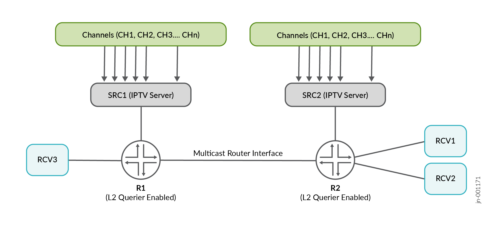
SRC1 and SRC2 are IPTV servers with a video headend, generating multiple IPTV channels - CH1, CH2 and CH3. The L2 querier is enabled on routers R1 and R2 to ensure that the hosts can refresh reports periodically, which will time out and remove the receivers from multicast forwarding otherwise.
In the topology above, router R2 has receivers interested in receiving channels CH1 and CH2 but will receive multicast streams from CH3 too. This is by virtue of it being a multicast-router interface.
Similarly, router R1 has a receiver interested only in channel CH3 but will receive unsolicited multicast streams from CH1 and CH2 over the multicast-router interface.
By configuring no-flood-to-multicast-router-interfaces, you can limit the
above-mentioned bandwidth inefficiency effectively by sending multicast streams only when
there are interested receivers behind a multicast-router interface.
This feature is specific to an L2 multicast environment.
If PIM-enabled L3 routers (with IGMP/MLD querier turned on implicitly) are present in the
topology and no-flood-to-multicast-router-interfaces is enabled, then it
may result in traffic outage for receivers behind the L3 multicast routers. This is because
multicast routers typically send PIM join messages on seeing an IGMP join from a last hop
router (LHR).
Based on your network design, no-flood-to-multicast-router-interfaces must
be used judiciously.
- Restricting flooding of unknown multicast traffic in an EVPN environment
- Flood Reports to Inter-switch Links and Automatic Immediate Leave on Host Links
Restricting flooding of unknown multicast traffic in an EVPN environment
Let us take an example of a typical EVPN topology which is an EVPNoVXLAN bridge overlay with SMET (Selective multicast forwarding) enabled. EVPN type 6 routes are advertised, ensuring forwarding of multicast traffic to interested receivers only.
There are IBC headend devices which are connected to a redundant external multicast-router and the EVPN fabric below. Since this is a bridge overlay there is only L2 connectivity from the redundant external multicast routers where IRB is enabled without snooping. The multicast traffic coming into the external multicast routers are bridged or L2 switched when traffic needs to egress from the IRB.
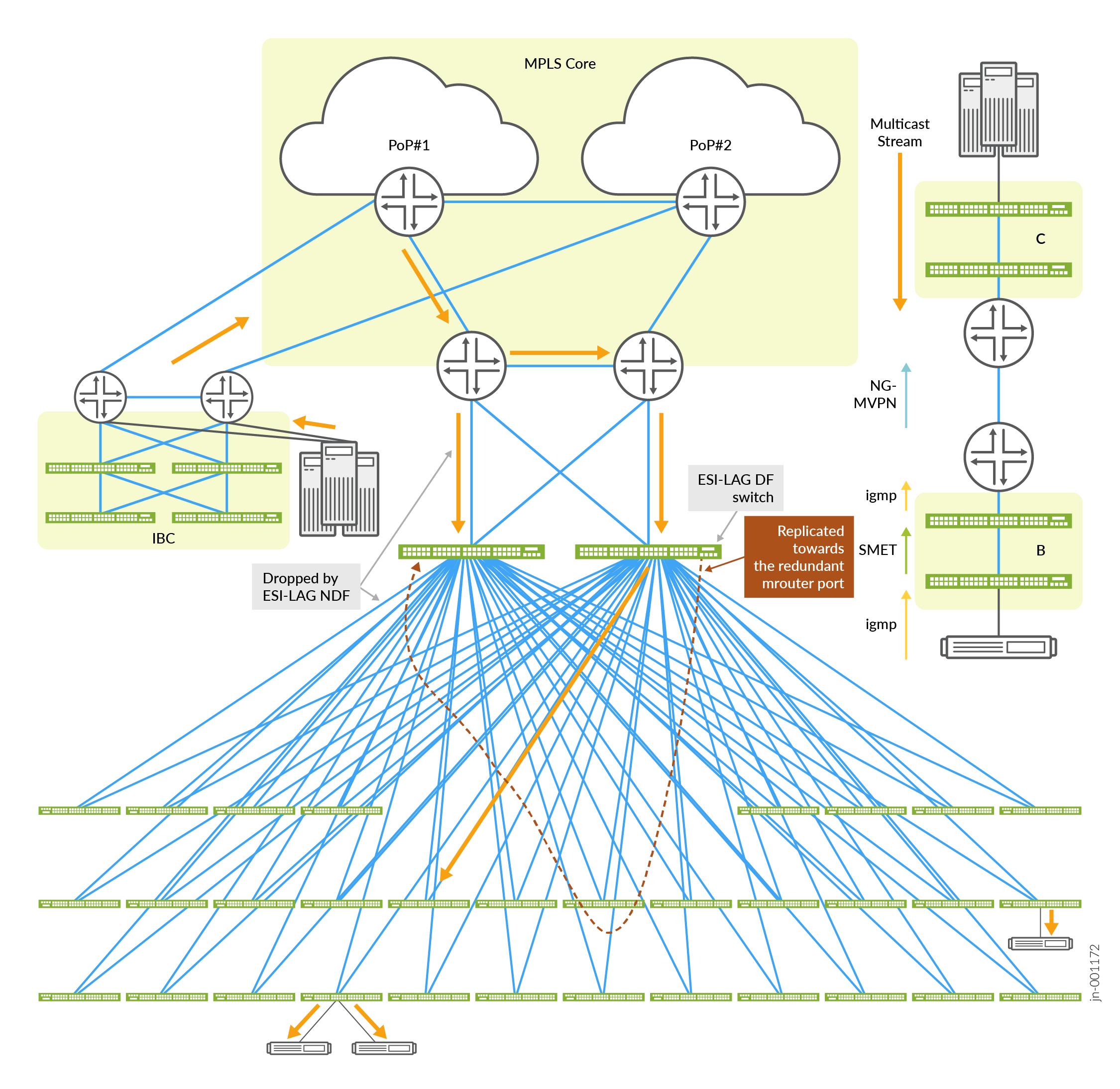
With SMET bridged overlay fabric stitched to the redundant external multicast-router ports,
multicast traffic entering one multicast-router port is circled via the fabric access
switches back to the second multicast-router port (the orange dotted line in Figure 4).
The EVPN PE device attracts all multicast traffic, known and unknown over the EVPN core.
Typically, EVPN PEs send EVPN Type 3 routes that have multicast extended community flags
without the IGMP/MLD snooping proxy set in its NLRI. By setting the
no-flood-to-multicast-router-interfaces configuration statement, the EVPN
Type 3 routes are sent with multicast extended community flags with the IGMP/MLD snooping
proxy flags set. As a result, the multicast-router interface will not attract unknown
multicast traffic.
This feature is typically implemented in an EVPN bridge overlay scenario. If L3 routing
is operational across the external multicast router, enabling
no-flood-to-multicast-router-interfaces may result in traffic
outage.
Flood Reports to Inter-switch Links and Automatic Immediate Leave on Host Links
Let’s take an example of a Layer 2 multicast video deployment topology that has a spine switch connected to two leaf switches. The spine switch is a layer 2 querier. There are hosts connected to the two leaf switches which can be either sources or receivers. The link connecting the leaf and spine switches is the inter-switch link (ISL) also known as the core-facing link.
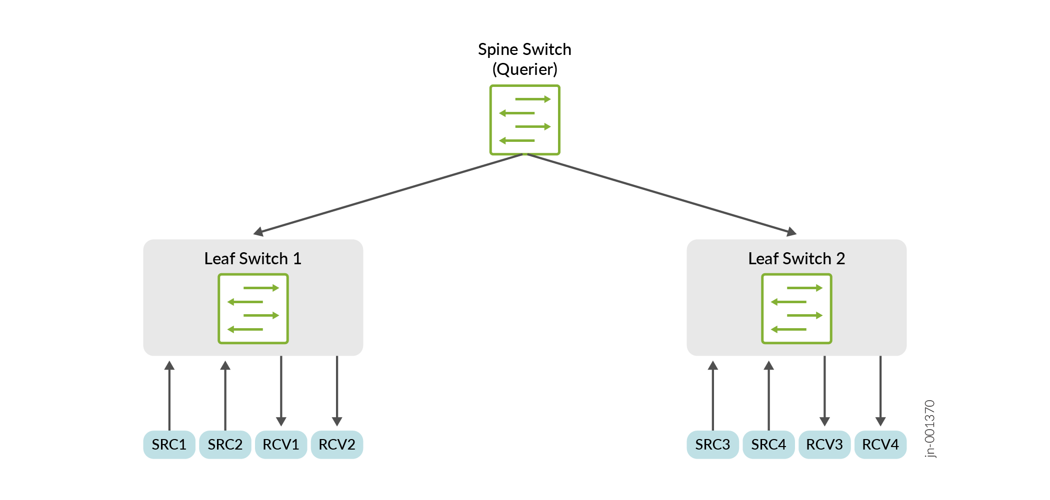
The link connecting the leaf switch and hosts is known as the host link. Since the spine switch acts as the querier, the link connecting the leaf switches to the spine switch is marked as the multicast-router interface.
For example, receiver RCV4 is interested in a multicast stream from source SRC1. In a typical L2 multicast flow, the reports are sent only to the multicast-router interfaces.
Therefore, the IGMP/MLD reports from RCV4 will be sent to leaf switch 2 and further
forwarded to the spine switch by virtue of these being multicast-router interfaces. The
IGMP/MLD reports will stop at the querier (the spine switch) and not be forwarded further.
With <no-flood-to-multicast-router-interfaces> enabled, the multicast
stream will not be sent to the spine switch.
To avoid this issue, you can flood IGMP/MLD reports to the ISL and restrict sending it to
the host links by enabling the configuration statement
<flood-reports-to-inter-switch-interface> at the <edit
protocols igmp-snooping vlan <vlan-name>> hierarchy or at the <edit
bridge-domains <bd-name> protocols igmp-snooping> level.
In most L2 video deployments, immediate-leave is required to improve leave convergence and
assist in the seamless transition from one channel to another with minimal latency. By
configuring the <immediate-leave-on-host-interface> statement under the
<edit protocols igmp-snooping vlan <vlan-name> or the
<edit bridge-domains protocols igmp-snooping> hierarchy, you can
enable automatic immediate-leave on all host links on a vlan or bridge-domain level. The
<immediate-leave-on-host-interface> statement automatically detects
host interfaces and configures immediate-leave for those interfaces.