ON THIS PAGE
Multicast Overview
IP has three fundamental types of addresses: unicast, broadcast, and multicast. A unicast address is used to send a packet to a single destination. A broadcast address is used to send a datagram to an entire subnetwork. A multicast address is used to send a datagram to a set of hosts that can be on different subnetworks and that are configured as members of a multicast group.
A multicast datagram is delivered to destination group members with the same best-effort reliability as a standard unicast IP datagram. This means that multicast datagrams are not guaranteed to reach all members of a group or to arrive in the same order in which they were transmitted. The only difference between a multicast IP packet and a unicast IP packet is the presence of a group address in the IP header destination address field. Multicast addresses use the Class D address format.
Individual hosts can join or leave a multicast group at any time. There are no restrictions on the physical location or the number of members in a multicast group. A host can be a member of more than one multicast group at any time. A host does not have to belong to a group to send packets to members of a group.
Routers use a group membership protocol to learn about the presence of group members on directly attached subnetworks. When a host joins a multicast group, it transmits a group membership protocol message for the group or groups that it wants to receive and sets its IP process and network interface card to receive frames addressed to the multicast group.
Comparing Multicast to Unicast
The Junos® operating system (Junos OS) routing protocol process supports a wide variety of routing protocols. These routing protocols carry network information among routing devices not only for unicast traffic streams sent between one pair of clients and servers, but also for multicast traffic streams containing video, audio, or both, between a single server source and many client receivers. The routing protocols used for multicast differ in many key ways from unicast routing protocols.
Information is delivered over a network by three basic methods: unicast, broadcast, and multicast.
The differences among unicast, broadcast, and multicast can be summarized as follows:
-
Unicast: One-to-one, from one source to one destination.
-
Broadcast: One-to-all, from one source to all possible destinations.
-
Multicast: One-to-many, from one source to multiple destinations expressing an interest in receiving the traffic.
Note:This list does not include a special category for many-to-many applications, such as online gaming or videoconferencing, where there are many sources for the same receiver and where receivers often double as sources. Many-to-many is a service model that repeatedly employs one-to-many multicast and therefore requires no unique protocol. The original multicast specification, RFC 1112, supports both the any-source multicast (ASM) many-to-many model and the source-specific multicast (SSM) one-to-many model.
With unicast traffic, many streams of IP packets that travel across networks flow from a single source, such as a website server, to a single destination such as a client PC. Unicast traffic is still the most common form of information transfer on networks.
Broadcast traffic flows from a single source to all possible destinations reachable on the network, which is usually a LAN. Broadcasting is the easiest way to make sure traffic reaches its destinations.
Television networks use broadcasting to distribute video and audio. Even if the television network is a cable television (CATV) system, the source signal reaches all possible destinations, which is the main reason that some channels’ content is scrambled. Broadcasting is not feasible on the Internet because of the enormous amount of unnecessary information that would constantly arrive at each end user's device, the complexities and impact of scrambling, and related privacy issues.
Multicast traffic lies between the extremes of unicast (one source, one destination) and broadcast (one source, all destinations). Multicast is a “one source, many destinations” method of traffic distribution, meaning only the destinations that explicitly indicate their need to receive the information from a particular source receive the traffic stream.
On an IP network, because destinations (clients) do not often communicate directly with sources (servers), the routing devices between source and destination must be able to determine the topology of the network from the unicast or multicast perspective to avoid routing traffic haphazardly. Multicast routing devices replicate packets received on one input interface and send the copies out on multiple output interfaces.
In IP multicast, the source and destination are almost always hosts and not routing devices. Multicast routing devices distribute the multicast traffic across the network from source to destinations. The multicast routing device must find multicast sources on the network, send out copies of packets on several interfaces, prevent routing loops, connect interested destinations with the proper source, and keep the flow of unwanted packets to a minimum. Standard multicast routing protocols provide most of these capabilities, but some router architectures cannot send multiple copies of packets and so do not support multicasting directly.
IP Multicast Uses
Multicast allows an IP network to support more than just the unicast model of data delivery that prevailed in the early stages of the Internet. Multicast, originally defined as a host extension in RFC 1112 in 1989, provides an efficient method for delivering traffic flows that can be characterized as one-to-many or many-to-many.
Unicast traffic is not strictly limited to data applications. Telephone conversations, wireless or not, contain digital audio samples and might contain digital photographs or even video and still flow from a single source to a single destination. In the same way, multicast traffic is not strictly limited to multimedia applications. In some data applications, the flow of traffic is from a single source to many destinations that require the packets, as in a news or stock ticker service delivered to many PCs. For this reason, the term receiver is preferred to listener for multicast destinations, although both terms are common.
Network applications that can function with unicast but are better suited for multicast include collaborative groupware, teleconferencing, periodic or “push” data delivery (stock quotes, sports scores, magazines, newspapers, and advertisements), server or website replication, and distributed interactive simulation (DIS) such as war simulations or virtual reality. Any IP network concerned with reducing network resource overhead for one-to-many or many-to-many data or multimedia applications with multiple receivers benefits from multicast.
If unicast were employed by radio or news ticker services, each radio or PC would have to have a separate traffic session for each listener or viewer at a PC (this is actually the method for some Web-based services). The processing load and bandwidth consumed by the server would increase linearly as more people “tune in” to the server. This is extremely inefficient when dealing with the global scale of the Internet. Unicast places the burden of packet duplication on the server and consumes more and more backbone bandwidth as the number of users grows.
If broadcast were employed instead, the source could generate a single IP packet stream using a broadcast destination address. Although broadcast eliminates the server packet duplication issue, this is not a good solution for IP because IP broadcasts can be sent only to a single subnetwork, and IP routing devices normally isolate IP subnetworks on separate interfaces. Even if an IP packet stream could be addressed to literally go everywhere, and there were no need to “tune” to any source at all, broadcast would be extremely inefficient because of the bandwidth strain and need for uninterested hosts to discard large numbers of packets. Broadcast places the burden of packet rejection on each host and consumes the maximum amount of backbone bandwidth.
For radio station or news ticker traffic, multicast provides the most efficient and effective outcome, with none of the drawbacks and all of the advantages of the other methods. A single source of multicast packets finds its way to every interested receiver. As with broadcast, the transmitting host generates only a single stream of IP packets, so the load remains constant whether there is one receiver or one million. The network routing devices replicate the packets and deliver the packets to the proper receivers, but only the replication role is a new one for routing devices. The links leading to subnets consisting of entirely uninterested receivers carry no multicast traffic. Multicast minimizes the burden placed on sender, network, and receiver.
IP Multicast Terminology
Multicast has its own particular set of terms and acronyms that apply to IP multicast routing devices and networks. Figure 1 depicts some of the terms commonly used in an IP multicast network.
In a multicast network, the key component is the routing device, which is able to replicate packets and is therefore multicast-capable. The routing devices in the IP multicast network, which has exactly the same topology as the unicast network it is based on, use a multicast routing protocol to build a distribution tree that connects receivers (preferred to the multimedia implications of listeners, but listeners is also used) to sources. In multicast terminology, the distribution tree is rooted at the source (the root of the distribution tree is the source). The interface on the routing device leading toward the source is the upstream interface, although the less precise terms incoming or inbound interface are used as well. To keep bandwidth use to a minimum, it is best for only one upstream interface on the routing device to receive multicast packets. The interface on the routing device leading toward the receivers is the downstream interface, although the less precise terms outgoing or outbound interface are used as well. There can be 0 to N–1 downstream interfaces on a routing device, where N is the number of logical interfaces on the routing device. To prevent looping, the upstream interface must never receive copies of downstream multicast packets.
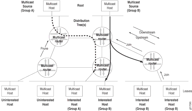
Routing loops are disastrous in multicast networks because of the risk of repeatedly replicated packets. One of the complexities of modern multicast routing protocols is the need to avoid routing loops, packet by packet, much more rigorously than in unicast routing protocols.
Reverse-Path Forwarding for Loop Prevention
The routing device's multicast forwarding state runs more logically based on the reverse path, from the receiver back to the root of the distribution tree. In RPF, every multicast packet received must pass an RPF check before it can be replicated or forwarded on any interface.
When a router receives a multicast packet on an interface, the router verifies the source address. The router then checks to see if the same address could be used as the destination address to get back to the source via a unicast route. If the outgoing interface found in the unicast routing table is the same interface that the multicast packet was received on, the packet passes the RPF check.
Multicast packets that fail the RPF check are dropped, because the incoming interface is not on the shortest path back to the source. Routing devices can build and maintain separate tables for RPF purposes.
Shortest-Path Tree for Loop Prevention
The distribution tree used for multicast is rooted at the source and is the shortest-path tree (SPT), but this path can be long if the source is at the periphery of the network. Providing a shared tree on the backbone as the distribution tree locates the multicast source more centrally in the network. Shared distribution trees with roots in the core network are created and maintained by a multicast routing device operating as a rendezvous point (RP), a feature of sparse mode multicast protocols.
Administrative Scoping for Loop Prevention
Scoping limits the routing devices and interfaces that can forward a multicast packet. Multicast scoping is administrative in the sense that a range of multicast addresses is reserved for scoping purposes, as described in RFC 2365, Administratively Scoped IP Multicast. Routing devices at the boundary must filter multicast packets and ensure that packets do not stray beyond the established limit.
Multicast Leaf and Branch Terminology
Each subnetwork with hosts on the routing device that has at least one interested receiver is a leaf on the distribution tree. Routing devices can have multiple leaves on different interfaces and must send a copy of the IP multicast packet out on each interface with a leaf. When a new leaf subnetwork is added to the tree (that is, the interface to the host subnetwork previously received no copies of the multicast packets), a new branch is built, the leaf is joined to the tree, and replicated packets are sent out on the interface. The number of leaves on a particular interface does not affect the routing device. The action is the same for one leaf or a hundred.
On Juniper Networks security devices, if the maximum number of leaves on a multicast distribution tree is exceeded, multicast sessions are created up to the maximum number of leaves, and any multicast sessions that exceed the maximum number of leaves are ignored. The maximum number of leaves on a multicast distribution tree is device specific.
When a branch contains no leaves because there are no interested hosts on the routing device interface leading to that IP subnetwork, the branch is pruned from the distribution tree, and no multicast packets are sent out that interface. Packets are replicated and sent out multiple interfaces only where the distribution tree branches at a routing device, and no link ever carries a duplicate flow of packets.
Collections of hosts all receiving the same stream of IP packets, usually from the same multicast source, are called groups. In IP multicast networks, traffic is delivered to multicast groups based on an IP multicast address, or group address. The groups determine the location of the leaves, and the leaves determine the branches on the multicast network.
IP Multicast Addressing
Multicast uses the Class D IP address range (224.0.0.0 through 239.255.255.255). Class D addresses are commonly referred to as multicast addresses because the entire classful address concept is obsolete. Multicast addresses can never appear as the source address in an IP packet and can only be the destination of a packet.
Multicast addresses usually have a prefix length of /32, although other prefix lengths are allowed. Multicast addresses represent logical groupings of receivers and not physical collections of devices. Blocks of multicast addresses can still be described in terms of prefix length in traditional notation, but only for convenience. For example, the multicast address range from 232.0.0.0 through 232.255.255.255 can be written as 232.0.0.0/8 or 232/8.
Internet service providers (ISPs) do not typically allocate multicast addresses to their customers because multicast addresses relate to content, not to physical devices. Receivers are not assigned their own multicast addresses, but need to know the multicast address of the content. Sources need to be assigned multicast addresses only to produce the content, not to identify their place in the network. Every source and receiver still needs an ordinary, unicast IP address.
Multicast addressing most often references the receivers, and the source of multicast content is usually not even a member of the multicast group for which it produces content. If the source needs to monitor the packets it produces, monitoring can be done locally, and there is no need to make the packets traverse the network.
Many applications have been assigned a range of multicast addresses for their own use. These applications assign multicast addresses to sessions created by that application. You do not usually need to statically assign a multicast address, but you can do so.
Multicast Addresses
Multicast host group addresses are defined to be the IP addresses whose high-order four bits are 1110, giving an address range from 224.0.0.0 through 239.255.255.255, or simply 224.0.0.0/4. (These addresses also are referred to as Class D addresses.)
The Internet Assigned Numbers Authority (IANA) maintains a list of registered IP multicast groups. The base address 224.0.0.0 is reserved and cannot be assigned to any group. The block of multicast addresses from 224.0.0.1 through 224.0.0.255 is reserved for local wire use. Groups in this range are assigned for various uses, including routing protocols and local discovery mechanisms.
The range from 239.0.0.0 through 239.255.255.255 is reserved for administratively scoped addresses. Because packets addressed to administratively scoped multicast addresses do not cross configured administrative boundaries, and because administratively scoped multicast addresses are locally assigned, these addresses do not need to be unique across administrative boundaries.
Layer 2 Frames and IPv4 Multicast Addresses
Multicasting on a LAN is a good place to start an investigation of multicasting at Layer 2. At Layer 2, multicast deals with media access control (MAC) frames and addresses instead of IPv4 or IPv6 packets and addresses. Consider a single LAN, without routing devices, with a multicast source sending to a certain group. The rest of the hosts are receivers interested in the multicast group’s content. So the multicast source host generates packets with its unicast IP address as the source, and the multicast group address as the destination.
Which MAC addresses are used on the frame containing this packet? The packet source address—the unicast IP address of the host originating the multicast content—translates easily and directly to the MAC address of the source. But what about the packet’s destination address? This is the IP multicast group address. Which destination MAC address for the frame corresponds to the packet’s multicast group address?
One option is for LANs simply to use the LAN broadcast MAC address, which guarantees that the frame is processed by every station on the LAN. However, this procedure defeats the whole purpose of multicast, which is to limit the circulation of packets and frames to interested hosts. Also, hosts might have access to many multicast groups, which multiplies the amount of traffic to noninterested destinations. Broadcasting frames at the LAN level to support multicast groups makes no sense.
However, there is an easy way to effectively use Layer 2 frames for multicast purposes. The MAC address has a bit that is set to 0 for unicast (the LAN term is individual address) and set to 1 to indicate that this is a multicast address. Some of these addresses are reserved for multicast groups of specific vendors or MAC-level protocols. Internet multicast applications use the range 0x01-00-5E-00-00-00 to 0x01-00-5E-FF-FF-FF. Multicast receivers (hosts running TCP/IP) listen for frames with one of these addresses when the application joins a multicast group. The host stops listening when the application terminates or the host leaves the group at the packet layer (Layer 3).
This means that 3 bytes, or 24 bits, are available to map IPv4 multicast addresses at Layer 3 to MAC multicast addresses at Layer 2. However, all IPv4 addresses, including multicast addresses, are 32 bits long, leaving 8 IP address bits left over. Which method of mapping IPv4 multicast addresses to MAC multicast addresses minimizes the chance of “collisions” (that is, two different IP multicast groups at the packet layer mapping to the same MAC multicast address at the frame layer)?
First, it is important to realize that all IPv4 multicast addresses begin with the same 4 bits (1110), so there are really only 4 bits of concern, not 8. A LAN must not drop the last bits of the IPv4 address because these are almost guaranteed to be host bits, depending on the subnet mask. But the high-order bits, the leftmost address bits, are almost always network bits, and there is only one LAN (for now).
One other bit of the remaining 24 MAC address bits is reserved (an initial 0 indicates an Internet multicast address), so the 5 bits following the initial 1110 in the IPv4 address are dropped. The 23 remaining bits are mapped, one for one, into the last 23 bits of the MAC address. An example of this process is shown in Figure 2.
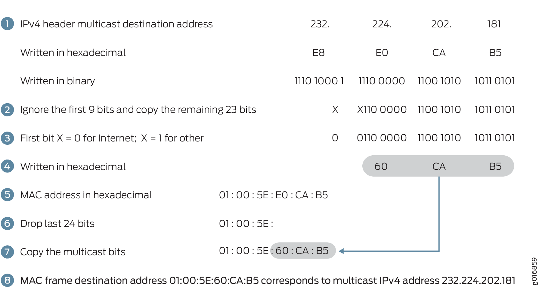
Note that this process means that there are 32 (25) IPv4 multicast addresses that could map to the same MAC multicast addresses. For example, multicast IPv4 addresses 224.8.7.6 and 229.136.7.6 translate to the same MAC address (0x01-00-5E-08-07-06). This is a real concern, and because the host could be interested in frames sent to both of the those multicast groups, the IP software must reject one or the other.
This “collision” problem does not exist in IPv6 because of the way IPv6 handles multicast groups, but it is always a concern in IPv4. The procedure for placing IPv6 multicast packets inside multicast frames is nearly identical to that for IPv4, except for the MAC destination address 0x3333 prefix (and the lack of “collisions”).
Once the MAC address for the multicast group is determined, the host's operating system essentially orders the LAN interface card to join or leave the multicast group. Once joined to a multicast group, the host accepts frames sent to the multicast address as well as the host’s unicast address and ignores other multicast group’s frames. It is possible for a host to join and receive multicast content from more than one group at the same time, of course.
Multicast Interface Lists
To avoid multicast routing loops, every multicast routing device must always be aware of the interface that leads to the source of that multicast group content by the shortest path. This is the upstream (incoming) interface, and packets are never to be forwarded back toward a multicast source. All other interfaces are potential downstream (outgoing) interfaces, depending on the number of branches on the distribution tree.
Routing devices closely monitor the status of the incoming and outgoing interfaces, a process that determines the multicast forwarding state. A routing device with a multicast forwarding state for a particular multicast group is essentially “turned on” for that group's content. Interfaces on the routing device's outgoing interface list send copies of the group's packets received on the incoming interface list for that group. The incoming and outgoing interface lists might be different for different multicast groups.
The multicast forwarding state in a routing device is usually written in either (S,G) or (*,G) notation. These are pronounced “ess comma gee” and “star comma gee,” respectively. In (S,G), the S refers to the unicast IP address of the source for the multicast traffic, and the G refers to the particular multicast group IP address for which S is the source. All multicast packets sent from this source have S as the source address and G as the destination address.
The asterisk (*) in the (*,G) notation is a wildcard indicating that the state applies to any multicast application source sending to group G. So, if two sources are originating exactly the same content for multicast group 224.1.1.2, a routing device could use (*,224.1.1.2) to represent the state of a routing device forwarding traffic from both sources to the group.
Multicast Routing Protocols
Multicast routing protocols enable a collection of multicast routing devices to build (join) distribution trees when a host on a directly attached subnet, typically a LAN, wants to receive traffic from a certain multicast group, prune branches, locate sources and groups, and prevent routing loops.
There are several multicast routing protocols:
-
Distance Vector Multicast Routing Protocol (DVMRP)—The first of the multicast routing protocols and hampered by a number of limitations that make this method unattractive for large-scale Internet use. DVMRP is a dense-mode-only protocol, and uses the flood-and-prune or implicit join method to deliver traffic everywhere and then determine where the uninterested receivers are. DVMRP uses source-based distribution trees in the form (S,G), and builds its own multicast routing tables for RPF checks.
-
Multicast OSPF (MOSPF)—Extends OSPF for multicast use, but only for dense mode. However, MOSPF has an explicit join message, so routing devices do not have to flood their entire domain with multicast traffic from every source. MOSPF uses source-based distribution trees in the form (S,G).
-
Bidirectional PIM mode—A variation of PIM. Bidirectional PIM builds bidirectional shared trees that are rooted at a rendezvous point (RP) address. Bidirectional traffic does not switch to shortest path trees as in PIM-SM and is therefore optimized for routing state size instead of path length. This means that the end-to-end latency might be longer compared to PIM sparse mode. Bidirectional PIM routes are always wildcard-source (*,G) routes. The protocol eliminates the need for (S,G) routes and data-triggered events. The bidirectional (*,G) group trees carry traffic both upstream from senders toward the RP, and downstream from the RP to receivers. As a consequence, the strict reverse path forwarding (RPF)-based rules found in other PIM modes do not apply to bidirectional PIM. Instead, bidirectional PIM (*,G) routes forward traffic from all sources and the RP. Bidirectional PIM routing devices must have the ability to accept traffic on many potential incoming interfaces. Bidirectional PIM scales well because it needs no source-specific (S,G) state. Bidirectional PIM is recommended in deployments with many dispersed sources and many dispersed receivers.
-
PIM dense mode—In this mode of PIM, the assumption is that almost all possible subnets have at least one receiver wanting to receive the multicast traffic from a source, so the network is flooded with traffic on all possible branches, then pruned back when branches do not express an interest in receiving the packets, explicitly (by message) or implicitly (time-out silence). This is the dense mode of multicast operation. LANs are appropriate networks for dense-mode operation. Some multicast routing protocols, especially older ones, support only dense-mode operation, which makes them inappropriate for use on the Internet. In contrast to DVMRP and MOSPF, PIM dense mode allows a routing device to use any unicast routing protocol and performs RPF checks using the unicast routing table. PIM dense mode has an implicit join message, so routing devices use the flood-and-prune method to deliver traffic everywhere and then determine where the uninterested receivers are. PIM dense mode uses source-based distribution trees in the form (S,G), as do all dense-mode protocols. PIM also supports sparse-dense mode, with mixed sparse and dense groups, but there is no special notation for that operational mode. If sparse-dense mode is supported, the multicast routing protocol allows some multicast groups to be sparse and other groups to be dense.
-
PIM sparse mode—In this mode of PIM, the assumption is that very few of the possible receivers want packets from each source, so the network establishes and sends packets only on branches that have at least one leaf indicating (by message) an interest in the traffic. This multicast protocol allows a routing device to use any unicast routing protocol and performs reverse-path forwarding (RPF) checks using the unicast routing table. PIM sparse mode has an explicit join message, so routing devices determine where the interested receivers are and send join messages upstream to their neighbors, building trees from receivers to the rendezvous point (RP). PIM sparse mode uses an RP routing device as the initial source of multicast group traffic and therefore builds distribution trees in the form (*,G), as do all sparse-mode protocols. PIM sparse mode migrates to an (S,G) source-based tree if that path is shorter than through the RP for a particular multicast group's traffic. WANs are appropriate networks for sparse-mode operation, and indeed a common multicast guideline is not to run dense mode on a WAN under any circumstances.
-
Core Based Trees (CBT)—Shares all of the characteristics of PIM sparse mode (sparse mode, explicit join, and shared (*,G) trees), but is said to be more efficient at finding sources than PIM sparse mode. CBT is rarely encountered outside academic discussions. There are no large-scale deployments of CBT, commercial or otherwise.
-
PIM source-specific multicast (SSM)—Enhancement to PIM sparse mode that allows a client to receive multicast traffic directly from the source, without the help of an RP. Used with IGMPv3 to create a shortest-path tree between receiver and source.
-
IGMPv1—The original protocol defined in RFC 1112, Host Extensions for IP Multicasting. IGMPv1 sends an explicit join message to the routing device, but uses a timeout to determine when hosts leave a group. Three versions of the Internet Group Management Protocol (IGMP) run between receiver hosts and routing devices.
-
IGMPv2—Defined in RFC 2236, Internet Group Management Protocol, Version 2. Among other features, IGMPv2 adds an explicit leave message to the join message.
-
IGMPv3—Defined in RFC 3376, Internet Group Management Protocol, Version 3. Among other features, IGMPv3 optimizes support for a single source of content for a multicast group, or source-specific multicast (SSM). Used with PIM SSM to create a shortest-path tree between receiver and source.
-
Bootstrap Router (BSR) and Auto-Rendezvous Point (RP)—Allow sparse-mode routing protocols to find RPs within the routing domain (autonomous system, or AS). RP addresses can also be statically configured.
-
Multicast Source Discovery Protocol (MSDP)—Allows groups located in one multicast routing domain to find RPs in other routing domains. MSDP is not used on an RP if all receivers and sources are located in the same routing domain. Typically runs on the same routing device as PIM sparse mode RP. Not appropriate if all receivers and sources are located in the same routing domain.
-
Session Announcement Protocol (SAP) and Session Description Protocol (SDP)—Display multicast session names and correlate the names with multicast traffic. SDP is a session directory protocol that advertises multimedia conference sessions and communicates setup information to participants who want to join the session. A client commonly uses SDP to announce a conference session by periodically multicasting an announcement packet to a well-known multicast address and port using SAP.
-
Pragmatic General Multicast (PGM)—Special protocol layer for multicast traffic that can be used between the IP layer and the multicast application to add reliability to multicast traffic. PGM allows a receiver to detect missing information in all cases and request replacement information if the receiver application requires it.
The differences among the multicast routing protocols are summarized in Table 1.
|
Multicast Routing Protocol |
Dense Mode |
Sparse Mode |
Implicit Join |
Explicit Join |
(S,G) Source Tree |
(*,G) Shared Tree |
|---|---|---|---|---|---|---|
|
DVMRP |
Yes |
No |
Yes |
No |
Yes |
No |
|
MOSPF |
Yes |
No |
No |
Yes |
Yes |
No |
|
PIM dense mode |
Yes |
No |
Yes |
No |
Yes |
No |
|
PIM sparse mode |
No |
Yes |
No |
Yes |
Yes, maybe |
Yes, initially |
|
Bidirectional PIM |
No |
No |
No |
Yes |
No |
Yes |
|
CBT |
No |
Yes |
No |
Yes |
No |
Yes |
|
SSM |
No |
Yes |
No |
Yes |
Yes, maybe |
Yes, initially |
|
IGMPv1 |
No |
Yes |
No |
Yes |
Yes, maybe |
Yes, initially |
|
IGMPv2 |
No |
Yes |
No |
Yes |
Yes, maybe |
Yes, initially |
|
IGMPv3 |
No |
Yes |
No |
Yes |
Yes, maybe |
Yes, initially |
|
BSR and Auto-RP |
No |
Yes |
No |
Yes |
Yes, maybe |
Yes, initially |
|
MSDP |
No |
Yes |
No |
Yes |
Yes, maybe |
Yes, initially |
It is important to realize that retransmissions due to a high bit-error rate on a link or overloaded routing device can make multicast as inefficient as repeated unicast. Therefore, there is a trade-off in many multicast applications regarding the session support provided by the Transmission Control Protocol (TCP) (but TCP always resends missing segments), or the simple drop-and-continue strategy of the User Datagram Protocol (UDP) datagram service (but reordering can become an issue). Modern multicast uses UDP almost exclusively.
Platform-Specific Multicast Behavior
Use Feature Explorer to confirm platform and release support for specific features.
Use the following table to review platform-specific behavior for your platform.
|
Platform |
Difference |
|---|---|
|
SRX Series |
|