ON THIS PAGE
Examples: Configuring Bandwidth Management
Understanding Bandwidth Management for Multicast
Bandwidth management enables you to control the multicast flows that leave a multicast interface. This control enables you to better manage your multicast traffic and reduce or eliminate the chances of interface oversubscription or congestion.
Bandwidth management ensures that multicast traffic oversubscription does not occur on an interface. When managing multicast bandwidth, you define the maximum amount of multicast bandwidth that an individual interface can use as well as the bandwidth individual multicast flows use.
For example, the routing software cannot add a flow to an interface if doing so exceeds the allowed bandwidth for that interface. Under these circumstances, the interface is rejected. This rejection, however, does not prevent a multicast protocol (for example, PIM) from sending a join message upstream. Traffic continues to arrive on the router, even though the router is not sending the flow from the expected outgoing interfaces.
You can configure the flow bandwidth statically by specifying a bandwidth value for the flow in bits per second, or you can enable the flow bandwidth to be measured and adaptively changed. When using the adaptive bandwidth option, the routing software queries the statistics for the flows to be measured at 5-second intervals and calculates the bandwidth based on the queries. The routing software uses the maximum value measured within the last minute (that is, the last 12 measuring points) as the flow bandwidth.
For more information, see the following sections:
Bandwidth Management and PIM Graceful Restart
When using PIM graceful restart, after the routing process restarts on the Routing Engine, previously admitted interfaces are always readmitted and the available bandwidth is adjusted on the interfaces. When using the adaptive bandwidth option, the bandwidth measurement is initially based on the configured or default starting bandwidth, which might be inaccurate during the first minute. This means that new flows might be incorrectly rejected or admitted temporarily. You can correct this problem by issuing the clear multicast bandwidth-admission operational command.
If PIM graceful restart is not configured, after the routing process restarts, previously admitted or rejected interfaces might be rejected or admitted in an unpredictable manner.
See Also
Bandwidth Management and Source Redundancy
When using source redundancy, multiple sources (for example, s1 and s2) might exist for the same destination group (g). However, only one of the sources can actively transmit at any time. In this case, multiple forwarding entries—(s1,g) and (s2,g)—are created after each goes through the admission process.
With redundant sources, unlike unrelated entries, an OIF that is already admitted for one entry—for example, (s1,g)—is automatically admitted for other redundancy entries—for example, (s2,g). The remaining bandwidth on the interface is deducted each time an outbound interface is added, even though only one sender actively transmits. By measuring bandwidth, the bandwidth deducted for the inactive entries is credited back when the router detects no traffic is being transmitted.
For more information about defining redundant sources, see Example: Configuring a Multicast Flow Map.
Logical Systems and Bandwidth Oversubscription
You can manage bandwidth at both the physical and logical interface level. However, if more than one logical system shares the same physical interface, the interface might become oversubscribed. Oversubscription occurs if the total bandwidth of all separately configured maximum bandwidth values for the interfaces on each logical system exceeds the bandwidth of the physical interface.
When displaying interface bandwidth information, a negative available bandwidth value indicates oversubscription on the interface.
Interface bandwidth can become oversubscribed when the configured maximum bandwidth decreases or when some flow bandwidths increase because of a configuration change or an actual increase in the traffic rate.
Interface bandwidth can become available again if one of the following occurs:
The configured maximum bandwidth increases.
Some flows are no longer transmitted from interfaces, and bandwidth reserves for them are now available to other flows.
Some flow bandwidths decrease because of a configuration change or an actual decrease in the traffic rate.
Interfaces that are rejected for a flow because of insufficient bandwidth are not automatically readmitted, even when bandwidth becomes available again. Rejected interfaces have an opportunity to be readmitted when one of the following occurs:
The multicast routing protocol updates the forwarding entry for the flow after receiving a join, leave, or prune message or after a topology change occurs.
The multicast routing protocol updates the forwarding entry for the flow due to configuration changes.
You manually reapply bandwidth management to a specific flow or to all flows using the clear multicast bandwidth-admission operational command.
In addition, even if previously available bandwidth is no longer available, already admitted interfaces are not removed until one of the following occurs:
The multicast routing protocol explicitly removes the interfaces after receiving a leave or prune message or after a topology change occurs.
You manually reapply bandwidth management to a specific flow or to all flows using the clear multicast bandwidth-admission operational command.
See Also
Example: Defining Interface Bandwidth Maximums
This example shows you how to configure the maximum bandwidth for a physical or logical interface.
Requirements
Before you begin:
Configure the router interfaces.
Configure an interior gateway protocol. See the Junos OS Routing Protocols Library for Routing Devices.
Configure a multicast protocol. This feature works with the following multicast protocols:
DVMRP
PIM-DM
PIM-SM
PIM-SSM
Overview
The maximum bandwidth setting applies admission control either against the configured interface bandwidth or against the native speed of the underlying interface (when there is no configured bandwidth for the interface).
If you configure several logical interfaces (for example, to support VLANs or PVCs) on the same underlying physical interface, and no bandwidth is configured for the logical interfaces, it is assumed that the logical interfaces all have the same bandwidth as the underlying interface. This can cause oversubscription. To prevent oversubscription, configure bandwidth for the logical interfaces, or configure admission control at the physical interface level.
You only need to define the maximum bandwidth for an interface on which you want to apply bandwidth management. An interface that does not have a defined maximum bandwidth transmits all multicast flows as determined by the multicast protocol that is running on the interface (for example, PIM).
If you specify maximum-bandwidth without including a bits-per-second value, admission control is enabled based on the bandwidth configured for the interface. In the following example, admission control is enabled for logical interface unit 200, and the maximum bandwidth is 20 Mbps. If the bandwidth is not configured on the interface, the maximum bandwidth is the link speed.
routing-options {
    multicast {
        interface fe-0/2/0.200 {
            maximum-bandwidth;
        }
interfaces {
    fe-0/2/0 {
        unit 200 {
            bandwidth 20m;
        }
    }
}
Topology
Configuration
Procedure
CLI Quick Configuration
To quickly configure this example, copy the
following commands, paste them into a text file, remove any line breaks,
change any details necessary to match your network configuration,
copy and paste the commands into the CLI at the [edit] hierarchy
level, and then enter commit from configuration mode.
set interfaces fe-0/2/0 unit 200 bandwidth 20m
set routing-options multicast interface fe-0/2/0.200 maximum-bandwidth
set routing-options multicast interface fe-0/2/1 maximum-bandwidth 60m
set routing-options multicast interface fe-0/2/1.200 maximum-bandwidth 10m
Step-by-Step Procedure
The following example requires you to navigate various levels in the configuration hierarchy. For information about navigating the CLI, see Using the CLI Editor in Configuration Mode in the Junos OS CLI User Guide.
To configure a bandwidth maximum:
Configure the a logical interface bandwidth.
[edit interfaces]
user@host# set fe-0/2/0 unit 200 bandwidth 20m
Enable admission control on the logical interface.
[edit routing-options]
user@host# set multicast interface fe-0/2/0.200 maximum-bandwidth
On a physical interface, enable admission control and set the maximum bandwidth to 60 Mbps.
[edit routing-options]
user@host# set multicast interface fe-0/2/1 maximum-bandwidth 60m
For a logical interface on the same physical interface shown in Step 3, set a smaller maximum bandwidth.
[edit routing-options]
user@host# set multicast interface fe-0/2/1.200 maximum-bandwidth 10m
Results
Confirm your configuration by entering the show interfaces and show routing-options commands.
user@host# show interfaces
fe-0/2/0 {
    unit 200 {
        bandwidth 20m;
    }
}
user@host# show routing-options
multicast {
    interface fe-0/2/0.200 {
        maximum-bandwidth;
    }
    interface fe-0/2/1 {
        maximum-bandwidth 60m;
    }
    interface fe-0/2/1.200 {
        maximum-bandwidth 10m;
    }
}
Verification
To verify the configuration, run the show multicast interface command.
Example: Configuring Multicast with Subscriber VLANs
This example shows how to configure an MX Series router to function as a broadband service router (BSR).
Requirements
This example uses the following hardware components:
One MX Series router or EX Series switch with a PIC that supports traffic control profile queuing
One DSLAM
Before you begin:
Configure an interior gateway protocol. See the Junos OS Routing Protocols Library for Routing Devices.
Configure PIM and IGMP or MLD on the interfaces.
Overview and Topology
When multiple BSR interfaces receive IGMP and MLD join and leave requests for the same multicast stream, the BSR sends a copy of the multicast stream on each interface. Both the multicast control packets (IGMP and MLD) and the multicast data packets flow on the same BSR interface, along with the unicast data. Because all per-customer traffic has its own interface on the BSR, per-customer accounting, call admission control (CAC), and quality-of-service (QoS) adjustment are supported. The QoS bandwidth used by multicast reduces the unicast bandwidth.
Multiple interfaces on the BSR might connect to a shared device (for example, a DSLAM). The BSR sends the same multicast stream multiple times to the shared device, thus wasting bandwidth. It is more efficient to send the multicast stream one time to the DSLAM and replicate the multicast streams in the DSLAM. There are two approaches that you can use.
The first approach is to continue to send unicast data on the per-customer interfaces, but have the DSLAM route all the per-customer IGMP and MLD join and leave requests to the BSR on a single dedicated interface (a multicast VLAN). The DSLAM receives the multicast streams from the BSR on the dedicated interface with no unnecessary replication and performs the necessary replication to the customers. Because all multicast control and data packets use only one interface, only one copy of a stream is sent even if there are multiple requests. This approach is called reverse outgoing interface (OIF) mapping. Reverse OIF mapping enables the BSR to propagate the multicast state of the shared interface to the customer interfaces, which enables per-customer accounting and QoS adjustment to work. When a customer changes the TV channel, the router gateway (RG) sends an IGMP or MLD join and leave messages to the DSLAM. The DSLAM transparently passes the request to the BSR through the multicast VLAN. The BSR maps the IGMP or MLD request to one of the subscriber VLANs based on the IP source address or the source MAC address. When the subscriber VLAN is found, QoS adjustment and accounting are performed on that VLAN or interface.
The second approach is for the DSLAM to continue to send unicast data and all the per-customer IGMP and MLD join and leave requests to the BSR on the individual customer interfaces, but to have the multicast streams arrive on a single dedicated interface. If multiple customers request the same multicast stream, the BSR sends one copy of the data on the dedicated interface. The DSLAM receives the multicast streams from the BSR on the dedicated interface and performs the necessary replication to the customers. Because the multicast control packets use many customer interfaces, configuration on the BSR must specify how to map each customer’s multicast data packets to the single dedicated output interface. QoS adjustment is supported on the customer interfaces. CAC is supported on the shared interface. This second approach is called multicast OIF mapping.
OIF mapping and reverse OIF mapping are not supported on the same customer interface or shared interface. This example shows how to configure the two different approaches. Both approaches support QoS adjustment, and both approaches support MLD/IPv6. The reverse OIF mapping example focuses on IGMP/IPv4 and enables QoS adjustment. The OIF mapping example focuses on MLD/IPv6 and disables QoS adjustment.
The first approach (reverse OIF mapping) includes the following statements:
flow-map—Defines a flow map that controls the bandwidth for each flow.
maximum-bandwidth—Enables CAC.
reverse-oif-mapping—Enables the routing device to identify a subscriber VLAN or interface based on an IGMP or MLD join or leave request that it receives over the multicast VLAN.
After the subscriber VLAN is identified, the routing device immediately adjusts the QoS (in this case, the bandwidth) on that VLAN based on the addition or removal of a subscriber.
The routing device uses IGMP and MLD join or leave reports to obtain the subscriber VLAN information. This means that the connecting equipment (for example, the DSLAM) must forward all IGMP and MLD reports to the routing device for this feature to function properly. Using report suppression or an IGMP proxy can result in reverse OIF mapping not working properly.
subscriber-leave-timer—Introduces a delay to the QoS update. After receiving an IGMP or MLD leave request, this statement defines a time delay (between 1 and 30 seconds) that the routing device waits before updating the QoS for the remaining subscriber interfaces. You might use this delay to decrease how often the routing device adjusts the overall QoS bandwidth on the VLAN when a subscriber sends rapid leave and join messages (for example, when changing channels in an IPTV network).
traffic-control-profile—Configures a shaping rate on the logical interface. The configured shaping rate must be configured as an absolute value, not as a percentage.
The second approach (OIF mapping) includes the following statements:
map-to-interface—In a policy statement, enables you to build the OIF map.
The OIF map is a routing policy statement that can contain multiple terms. When creating OIF maps, keep the following in mind:
If you specify a physical interface (for example, ge-0/0/0), a ".0" is appended to the interface to create a logical interface (for example, ge-0/0/0.0).
Configure a routing policy for each logical system. You cannot configure routing policies dynamically.
The interface must also have IGMP, MLD, or PIM configured.
You cannot map to a mapped interface.
We recommend that you configure policy statements for IGMP and MLD separately.
Specify either a logical interface or the keyword self. The self keyword specifies that multicast data packets be sent on the same interface as the control packets and that no mapping occur. If no term matches, then no multicast data packets are sent.
no-qos-adjust—Disables QoS adjustment.
QoS adjustment decreases the available bandwidth on the client interface by the amount of bandwidth consumed by the multicast streams that are mapped from the client interface to the shared interface. This action always occurs unless it is explicitly disabled.
If you disable QoS adjustment, available bandwidth is not reduced on the customer interface when multicast streams are added to the shared interface.
Note:You can dynamically disable QoS adjustment for IGMP and MLD interfaces using dynamic profiles.
oif-map—Associate a map with an IGMP or MLD interface. The OIF map is then applied to all IGMP or MLD requests received on the configured interface. In this example, subscriber VLANs 1 and 2 have MLD configured, and each VLAN points to an OIF map that directs some traffic to ge-2/3/9.4000, some traffic to ge-2/3/9.4001, and some traffic to self.
Note:You can dynamically associate OIF maps with IGMP interfaces using dynamic profiles.
passive—Defines either IGMP or MLD to use passive mode.
The OIF map interface should not typically pass IGMP or MLD control traffic and should be configured as passive. However, the OIF map implementation does support running IGMP or MLD on an interface (control and data) in addition to mapping data streams to the same interface. In this case, you should configure IGMP or MLD normally (that is, not in passive mode) on the mapped interface. In this example, the OIF map interfaces (ge-2/3/9.4000 and ge-2/3/9.4001) are configured as MLD passive.
By default, specifying the passive statement means that no general queries, group-specific queries, or group-source-specific queries are sent over the interface and that all received control traffic is ignored by the interface. However, you can selectively activate up to two out of the three available options for the passive statement while keeping the other functions passive (inactive).
These options include the following:
send-general-query—When specified, the interface sends general queries.
send-group-query—When specified, the interface sends group-specific and group-source-specific queries.
allow-receive—When specified, the interface receives control traffic.
Topology
Figure 1 shows the scenario.
In both approaches, if multiple customers request the same multicast stream, the BSR sends one copy of the stream on the shared multicast VLAN interface. The DSLAM receives the multicast stream from the BSR on the shared interface and performs the necessary replication to the customers.
In the first approach (reverse OIF mapping), the DSLAM uses the per-customer subscriber VLANs for unicast data only. IGMP and MLD join and leave requests are sent on the multicast VLAN.
In the second approach (OIF mapping), the DSLAM uses the per-customer subscriber VLANs for unicast data and for IGMP and MLD join and leave requests. The multicast VLAN is used only for multicast streams, not for join and leave requests.
Configuration
Configuring a Reverse OIF Map
CLI Quick Configuration
To quickly configure this example, copy the
following commands, paste them into a text file, remove any line breaks,
change any details necessary to match your network configuration,
copy and paste the commands into the CLI at the [edit] hierarchy
level, and then enter commit from configuration mode. .
set class-of-service traffic-control-profiles tcp-ifl shaping-rate 20m
set class-of-service interfaces ge-2/2/0 shaping-rate 240m
set class-of-service interfaces ge-2/2/0 unit 50 output-traffic-control-profile tcp-ifl
set class-of-service interfaces ge-2/2/0 unit 51 output-traffic-control-profile tcp-ifl
set interfaces ge-2/0/0 unit 0 family inet address 30.0.0.2/24
set interfaces ge-2/2/0 hierarchical-scheduler
set interfaces ge-2/2/0 vlan-tagging
set interfaces ge-2/2/0 unit 10 vlan-id 10
set interfaces ge-2/2/0 unit 10 family inet address 40.0.0.2/24
set interfaces ge-2/2/0 unit 50 vlan-id 50
set interfaces ge-2/2/0 unit 50 family inet address 50.0.0.2/24
set interfaces ge-2/2/0 unit 51 vlan-id 51
set interfaces ge-2/2/0 unit 51 family inet address 50.0.1.2/24
set policy-options policy-statement all-mcast-groups from source-address-filter 30.0.0.0/8 orlonger
set policy-options policy-statement all-mcast-groups then accept
set protocols igmp interface all
set protocols igmp interface fxp0.0 disable
set protocols pim rp local address 20.0.0.2
set protocols pim interface all
set protocols pim interface fxp0.0 disable
set protocols pim interface ge-2/2/0.10 disable
set routing-options multicast flow-map map1 policy all-mcast-groups
set routing-options multicast flow-map map1 bandwidth 10m
set routing-options multicast flow-map map1 bandwidth adaptive
set routing-options multicast interface ge-2/2/0.10 maximum-bandwidth 500m
set routing-options multicast interface ge-2/2/0.10 reverse-oif-mapping
set routing-options multicast interface ge-2/2/0.10 subscriber-leave-timer 20
Step-by-Step Procedure
The following example requires you to navigate various levels in the configuration hierarchy. For information about navigating the CLI, see Using the CLI Editor in Configuration Mode in the Junos OS CLI User Guide.
To configure reverse OIF mapping:
Configure a logical interface for unicast data traffic.
[edit interfaces ge-2/0/0]
user@host# set unit 0 family inet address 30.0.0.2/24
Configure a logical interface for subscriber control traffic.
[edit interfaces ge-2/2/0]
user@host# set hierarchical-scheduler
user@host# set vlan-tagging
user@host# set unit 10 vlan-id 10
user@host# set unit 10 family inet address 40.0.0.2/24
Configure two logical interfaces on which QoS adjustments are made.
[edit interfaces ge-2/2/0]
user@host# set unit 50 vlan-id 50
user@host# set unit 50 family inet address 50.0.0.2/24
user@host# set unit 51 vlan-id 51
user@host# set unit 51 family inet address 50.0.1.2/24
Configure a policy.
[edit policy-options policy-statement all-mcast-groups]
user@host# set from source-address-filter 30.0.0.0/8 orlonger
user@host# set then accept
Enable a flow map that references the policy.
[edit routing-options multicast]
user@host# set flow-map map1 policy all-mcast-groups
user@host# set flow-map map1 bandwidth 10m adaptive
Enable OIF mapping on the logical interface that receives subscriber control traffic.
[edit routing-options multicast]
user@host# set interface ge-2/2/0.10 maximum-bandwidth 500m
user@host# set interface ge-2/2/0.10 reverse-oif-mapping
user@host# set interface ge-2/2/0.10 subscriber-leave-timer 20
Configure PIM and IGMP.
[edit protocols]
user@host# set igmp interface all
user@host# set igmp interface fxp0.0 disable
user@host# set pim rp local address 20.0.0.2
user@host# set pim interface all
user@host# set pim interface fxp0.0 disable
user@host# set pim interface ge-2/2/0.10 disable
Configure the hierarchical scheduler by configuring a shaping rate for the physical interface and a slower shaping rate for the logical interfaces on which QoS adjustments are made.
[edit class-of-service interfaces ge-2/2/0]
user@host# set shaping-rate 240m
user@host# set unit 50 output-traffic-control-profile tcp-ifl
user@host# set unit 51 output-traffic-control-profile tcp-ifl
[edit class-of-service traffic-control-profiles tcp-30m-no-smap]
user@host# set shaping-rate 20m
Results
From configuration mode, confirm your configuration by entering the show class-of-service, show interfaces, show policy-options, show protocols, and show routing-options commands. If the output does not display the intended configuration, repeat the instructions in this example to correct the configuration.
user@host# show class-of-service
traffic-control-profiles {
    tcp-ifl {
        shaping-rate 20m;
    }
}
interfaces {
    ge-2/2/0 {
        shaping-rate 240m;
        unit 50 {
            output-traffic-control-profile tcp-ifl;
        }
        unit 51 {
            output-traffic-control-profile tcp-ifl;
        }
    }
}
user@host# show interfaces
ge-2/0/0 {
    unit 0 {
        family inet {
            address 30.0.0.2/24;
        }
    }
}
ge-2/2/0 {
    hierarchical-scheduler;
    vlan-tagging;
    unit 10 {
        vlan-id 10;
        family inet {
            address 40.0.0.2/24;
        }
    }
    unit 50 {
        vlan-id 50;
        family inet {
            address 50.0.0.2/24;
        }
    }
    unit 51 {
        vlan-id 51;
        family inet {
            address 50.0.1.2/24;
        }
    }
}
user@host# show policy-options
policy-statement all-mcast-groups {
    from {
        source-address-filter 30.0.0.0/8 orlonger;
    }
    then accept;
}
user@host# show protocols
igmp {
    interface all;
    interface fxp0.0 {
        disable;
    }
}
pim {
    rp {
        local {
            address 20.0.0.2;
        }
    }
    interface all;
    interface fxp0.0 {
        disable;
    }
    interface ge-2/2/0.10 {
        disable;
    }
}
user@host# show routing-options
multicast {
    flow-map map1 {
        policy all-mcast-groups;
        bandwidth 10m adaptive;
    }
    interface ge-2/2/0.10 {
        maximum-bandwidth 500m;
        reverse-oif-mapping;
        subscriber-leave-timer 20;
    }
}
If you are done configuring the device, enter commit from configuration mode.
Configuring an OIF Map
CLI Quick Configuration
To quickly configure this example, copy the
following commands, paste them into a text file, remove any line breaks,
change any details necessary to match your network configuration,
copy and paste the commands into the CLI at the [edit] hierarchy
level, and then enter commit from configuration mode.
set interfaces ge-2/3/8 unit 0 family inet6 address C300:0101::/24
set interfaces ge-2/3/9 vlan-tagging
set interfaces ge-2/3/9 unit 1 vlan-id 1
set interfaces ge-2/3/9 unit 1 family inet6 address C400:0101::/24
set interfaces ge-2/3/9 unit 2 vlan-id 2
set interfaces ge-2/3/9 unit 2 family inet6 address C400:0201::/24
set interfaces ge-2/3/9 unit 4000 vlan-id 4000
set interfaces ge-2/3/9 unit 4000 family inet6 address C40F:A001::/24
set interfaces ge-2/3/9 unit 4001 vlan-id 4001
set interfaces ge-2/3/9 unit 4001 family inet6 address C40F:A101::/24
set policy-options policy-statement g539-v6 term g539-4000 from route-filter FF05:0101:0000::/39 orlonger
set policy-options policy-statement g539-v6 term g539-4000 then map-to-interface ge-2/3/9.4000
set policy-options policy-statement g539-v6 term g539-4000 then accept
set policy-options policy-statement g539-v6 term g539-4001 from route-filter FF05:0101:0200::/39 orlonger
set policy-options policy-statement g539-v6 term g539-4001 then map-to-interface ge-2/3/9.4001
set policy-options policy-statement g539-v6 term g539-4001 then accept
set policy-options policy-statement g539-v6 term self from route-filter FF05:0101:0700::/40 orlonger
set policy-options policy-statement g539-v6 term self then map-to-interface self
set policy-options policy-statement g539-v6 term self then accept
set policy-options policy-statement g539-v6-all term g539 from route-filter 0::/0 orlonger
set policy-options policy-statement g539-v6-all term g539 then map-to-interface ge-2/3/9.4000
set policy-options policy-statement g539-v6-all term g539 then accept
set protocols mld interface fxp0.0 disable
set protocols mld interface ge-2/3/9.4000 passive
set protocols mld interface ge-2/3/9.4001 passive
set protocols mld interface ge-2/3/9.1 version 1
set protocols mld interface ge-2/3/9.1 oif-map g539-v6
set protocols mld interface ge-2/3/9.2 version 2
set protocols mld interface ge-2/3/9.2 oif-map g539-v6
set protocols pim rp local address 20.0.0.4
set protocols pim rp local family inet6 address C000::1
set protocols pim interface ge-2/3/8.0 mode sparse
set protocols pim interface ge-2/3/8.0 version 2
set routing-options multicast interface ge-2/3/9.1 no-qos-adjust
set routing-options multicast interface ge-2/3/9.2 no-qos-adjust
Step-by-Step Procedure
The following example requires you to navigate various levels in the configuration hierarchy. For information about navigating the CLI, see the Junos OS CLI User Guide.
To configure reverse OIF mapping:
Configure a logical interface for unicast data traffic.
[edit interfaces ge-2/3/8 ]
user@host# set unit 0 family inet6 address C300:0101::/24
Configure logical interfaces for subscriber VLANs.
[edit interfaces ge-2/3/9]
user@host# set vlan-tagging
user@host# set unit 1 vlan-id 1
user@host# set unit 1 family inet6 address C400:0101::/24
user@host# set unit 2 vlan-id 2
user@host# set unit 2 family inet6 address C400:0201::/24 lo0 unit 0 family inet6 address C000::1/128
user@host# set unit 2 family inet6 address C400:0201::/24
Configure two map-to logical interfaces.
[edit interfaces ge-2/2/0]
user@host# set unit 4000 vlan-id 4000
user@host# set unit 4000 family inet6 address C40F:A001::/24
user@host# set unit 4001 vlan-id 4001
user@host# set unit 4001 family inet6 address C40F:A101::/24
Configure the OIF map.
[edit policy-options policy-statement g539-v6]
user@host# set  term g539-4000 from route-filter FF05:0101:0000::/39 orlonger
user@host# set then map-to-interface ge-2/3/9.4000
user@host# set then accept
user@host# set term g539-4001 from route-filter FF05:0101:0200::/39 orlonger
user@host# set then map-to-interface ge-2/3/9.4001
user@host# set then accept
user@host# set term self from route-filter FF05:0101:0700::/40 orlonger
user@host# set then map-to-interface self
user@host# set then accept
[edit policy-options policy-statement g539-v6-all]
user@host# set term g539 from route-filter 0::/0 orlonger
user@host# set then map-to-interface ge-2/3/9.4000
user@host# set then accept
Disable QoS adjustment on the subscriber VLANs.
[edit routing-options multicast]
user@host# set interface ge-2/3/9.1 no-qos-adjust
user@host# set interface ge-2/3/9.2 no-qos-adjust
Configure PIM and MLD. Point the MLD subscriber VLANs to the OIF map.
[edit protocols]
user@host# set pim rp local address 20.0.0.4
user@host# set pim rp local family inet6 address C000::1 #C000::1 is the address of lo0
user@host# set pim interface ge-2/3/8.0 mode sparse
user@host# set pim interface ge-2/3/8.0 version 2
user@host# set mld interface fxp0.0 disable
user@host# set interface ge-2/3/9.4000 passive
user@host# set interface ge-2/3/9.4001 passive
user@host# set interface ge-2/3/9.1 version 1
user@host# set interface ge-2/3/9.1 oif-map g539-v6
user@host# set interface ge-2/3/9.2 version 2
user@host# set interface ge-2/3/9.2 oif-map g539-v6
Results
From configuration mode, confirm your configuration by entering the show interfaces, show policy-options, show protocols, and show routing-options commands. If the output does not display the intended configuration, repeat the instructions in this example to correct the configuration.
user@host# show interfaces
ge-2/3/8 {
    unit 0 {
        family inet6 {
            address C300:0101::/24;
        }
    }
}
ge-2/3/9 {
    vlan-tagging;
    unit 1 {
        vlan-id 1;
        family inet6 {
            address C400:0101::/24;
        }
    }
    unit 2 {
        vlan-id 2;
        family inet6 {
            address C400:0201::/24;
        }
    }
    unit 4000 {
        vlan-id 4000;
        family inet6 {
            address C40F:A001::/24;
        }
    }
    unit 4001 {
        vlan-id 4001;
        family inet6 {
            address C40F:A101::/24;
        }
    }
}
user@host# show policy-options
policy-statement g539-v6 {
    term g539-4000 {
        from {
            route-filter FF05:0101:0000::/39 orlonger;
        }
        then {
            map-to-interface ge-2/3/9.4000;
            accept;
        }
    }
    term g539-4001 {
        from {
            route-filter FF05:0101:0200::/39 orlonger;
        }
        then {
            map-to-interface ge-2/3/9.4001;
            accept;
        }
    }
    term self {
        from {
            route-filter FF05:0101:0700::/40 orlonger;
        }
        then {
            map-to-interface self;
            accept;
        }
    }
}
policy-statement g539-v6-all {
    term g539 {
        from {
            route-filter 0::/0 orlonger;
        }
        then {
            map-to-interface ge-2/3/9.4000;
            accept;
        }
    }
}
user@host# show protocols
mld {
    interface fxp0.0 {
        disable;
    }
    interface ge-2/3/9.4000 {
        passive;
    }
    interface ge-2/3/9.4001 {
        passive;
    }
    interface ge-2/3/9.1 {
        version 1;
        oif-map g539-v6;
    }
    interface ge-2/3/9.2 {
        version 2;
        oif-map g539-v6;
    }
}
pim {
    rp {
        local {
            address 20.0.0.4;
            family inet6 {
                address C000::1;
            }
        }
    }
    interface ge-2/3/8.0 {
        mode sparse;
        version 2;
    }
}
user@host# show routing-options
multicast {
    interface ge-2/3/9.1 no-qos-adjust;
    interface ge-2/3/9.2 no-qos-adjust;
}
If you are done configuring the device, enter commit from configuration mode.
Verification
To verify the configuration, run the following commands:
show igmp statistics
show class-of-service interface
show interfaces statistics
show mld statistics
show multicast interface
show policy
Configuring Multicast Routing over IP Demux Interfaces
In a subscriber management network, fields in packets sent from IP demux interfaces are intended to correspond to a specific client that resides on the other side of an aggregation device (for example, a Multiservice Access Node [MSAN]). However, packets sent from a Broadband Services Router (BSR) to an MSAN do not identify the demux interface. Once it obtains a packet, it is up to the MSAN device to determine which client receives the packet.
Depending on the intelligence of the MSAN device, determining which client receives the packet can occur in an inefficient manner. For example, when it receives IGMP control traffic, an MSAN might forward the control traffic to all clients instead of the one intended client. In addition, once a data stream destination is established, though an MSAN can use IGMP snooping to determine which hosts reside in a particular group and limit data streams to only that group, the MSAN still must send multiple copies of the data stream to each group member, even if that data stream is intended for only one client in the group.
Various multicast features, when combined, enable you to avoid the inefficiencies mentioned above. These features include the following:
The ability to configure the IP demux interface family statement to use inet for either the numbered or unnumbered primary interface.
The ability to configure IGMP on the primary interface to send general queries for all clients. The demux configuration prevents the primary IGMP interface from receiving any client IGMP control packets. Instead, all IGMP control packets go to the demux interfaces. However, to guarantee that no joins occur on the primary interface:
For static IGMP interfaces—Include the passive send-general-query statement in the IGMP configuration at the [edit protocols igmp interface interface-name] hierarchy level.
For dynamic IGMP demux interfaces—Include the passive send-general-query statement at the [edit dynamic-profiles profile-name protocols igmp interface interface-name] hierarchy level.
The ability to map all multicast groups to the primary interface as follows:
For static IGMP interfaces—Include the oif-map statement at the [edit protocols igmp interface interface-name] hierarchy level.
For dynamic IGMP demux interfaces—Include the oif-map statement at the [edit dynamic-profiles profile-name protocols igmp interface interface-name] hierarchy level.
Using the oif-map statement, you can map the same IGMP group to the same output interface and send only one copy of the multicast stream from the interface.
The ability to configure IGMP on each demux interface. To prevent duplicate general queries:
For static IGMP interfaces—Include the passive allow-receive send-group-query statement at the [edit protocols igmp interface interface-name] hierarchy level.
For dynamic demux interfaces—Include the passive allow-receive send-group-query statement at the [edit dynamic-profiles profile-name protocols igmp interface interface-name] hierarchy level.
Note:To send only one copy of each group, regardless of how many customers join, use the oif-map statement as previously mentioned.
See Also
Classify Packets by Egress Interface
On supported platforms, you can classify unicast and multicast packets based on the egress interface. For unicast traffic, you can also use a multifield filter, but only egress interface classification applies to multicast traffic as well as unicast traffic. If you configure egress classification of an interface, you cannot perform DSCP rewrites on the interface. By default, the system does not perform any classification based on the egress interface.
To enable packet classification by the egress interface, you first configure a forwarding
class map and one or more queue numbers for the egress interface at the [edit
class-of-service forwarding-class-map
forwarding-class-map-name] hierarchy level:
[edit class-of-service]
forwarding-class-map  forwarding-class-map-name {
    class class-name queue-num queue-number [ restricted-queue queue-number ];
}
If you configure an output forwarding class map associating a forwarding class with a
queue number, this map is not supported on multiservices link services IQ
(lsq-) interfaces.
Once the forwarding class map has been configured, you apply the map to the logical
interface by using the output-forwarding-class-map statement at the
[edit class-of-service interfaces interface-name unit
                    logical-unit-number ]
hierarchy level:
[edit class-of-service interfaces interface-name unit logical-unit-number]
output-forwarding-class-map forwarding-class-map-name;
All parameters relating to the queues and forwarding class must be configured as well. For more information about configuring forwarding classes and queues, see Configuring a Custom Forwarding Class for Each Queue.
You cannot apply a rewrite rule and output forwarding class map to the same logical interface (unit). Although a warning is issued, the CLI does not prevent this configuration. An error message appears when you attempt to commit the configuration.
This example shows how to configure an interface-specific forwarding-class map named
FCMAP1 that restricts queues 5 and 6 to different queues on
four-queue systems and then applies FCMAP1 to unit 0
of interface ge-6/0/0:
[edit class-of-service]
forwarding-class-map FCMAP1 {
    class FC1 queue-num 6 restricted-queue 3;
    class FC2 queue-num 5 restricted-queue 2;
    class FC3 queue-num 3;
    class FC4 queue-num 0;
    class FC3 queue-num 0;
    class FC4 queue-num 1;
}

[edit class-of-service]
interfaces {
    ge-6/0/0 unit 0 {
        output-forwarding-class-map FCMAP1;
    }
}
Note that without the restricted-queue option in
FCMAP1, the example would assign FC1 and
FC2 to queues 2 and 1, respectively, on a system restricted to four
queues.
Use the show class-of-service forwarding-class
forwarding-class-map-name command to display the
forwarding-class map queue configuration:
user@host> show class-of-service forwarding-class FCMAP2

Forwarding class                       ID      Queue  Restricted queue
  FC1                                   0       6          3
  FC2                                   1       5          2
  FC3                                   2       3          3
  FC4                                   3       0          0
  FC5                                   4       0          0
  FC6                                   5       1          1
  FC7                                   6       6          2
  FC8                                   7       7          3
Use the show class-of-service interface
interface-name command to display the forwarding-class
maps (and other information) assigned to a logical interface:
user@host> show class-of-service interface ge-6/0/0

Physical interface: ge-6/0/0, Index: 128
Queues supported: 8, Queues in use: 8
 Scheduler map: <default>, Index: 2
 Input scheduler map: <default>, Index: 3
 Chassis scheduler map: <default-chassis>, Index: 4

Logical interface: ge-6/0/0.0, Index: 67
 Object                      Name              Type                     Index
 Scheduler-map               sch-map1          Output                    6998
 Scheduler-map               sch-map1          Input                     6998
 Classifier                  dot1p             ieee8021p                 4906
 forwarding-class-map        FCMAP1            Output                    1221

Logical interface: ge-6/0/0.1, Index 68
 Object                      Name              Type                     Index
 Scheduler-map               <default>         Output                       2
 Scheduler-map               <default>         Input                        3

Logical interface: ge-6/0/0.32767, Index 69
 Object                      Name              Type                     Index
 Scheduler-map               <default>         Output                       2
 Scheduler-map               <default>         Input                        3
Platform-Specific Forwarding Class Behavior
Use Feature Explorer to confirm platform and release support for specific features.
Use the following table to review platform-specific behaviors for your platform:
| Platform | Difference |
|---|---|
|
MX Series |
On an MX Series router that contains MPCs and MS-DPCs, multicast packets are dropped on the router and not processed properly if the router contains MLPPP LSQ logical interfaces that function as multicast receivers and if the network services mode is configured as enhanced IP mode on the router. This behavior is expected with LSQ interfaces with enhanced IP mode. In such a scenario, if enhanced IP mode is not configured, multicasting works correctly. However, if the router contains redundant LSQ interfaces and enhanced IP network services mode configured with FIB localization, multicast works properly. |
Recycle Bandwidth Management
ACX routers use the recycle interface to loopback or recirculate traffic from the egress interface to the ingress for additional processing. This is needed for applications that require additional processing.
The recycle interface is an internal channelized interface that has an egress shaper that limits the flow rate of outbound traffic. By default, the recycle interface bandwidth is based on chassis oversubscription and platform specific FPC or interface configuration.
Applications that use the recycle mechanism, configure channels or virtual ports based on need, which in turn goes through an application shaper similar to the egress shaper on the recycle interface. The recycle interface can support a maximum of 256 channels or virtual logical ports. All the recycle channels operate at the same priority. The recycled traffic is then forwarded using the calendar slot based on the weight assigned to it. Other types of interfaces like the NIF interface forward traffic by occupying other slots on the calendar proportional to its bandwidth.
Figure 1 illustrates the the recycle mechanism and its components.
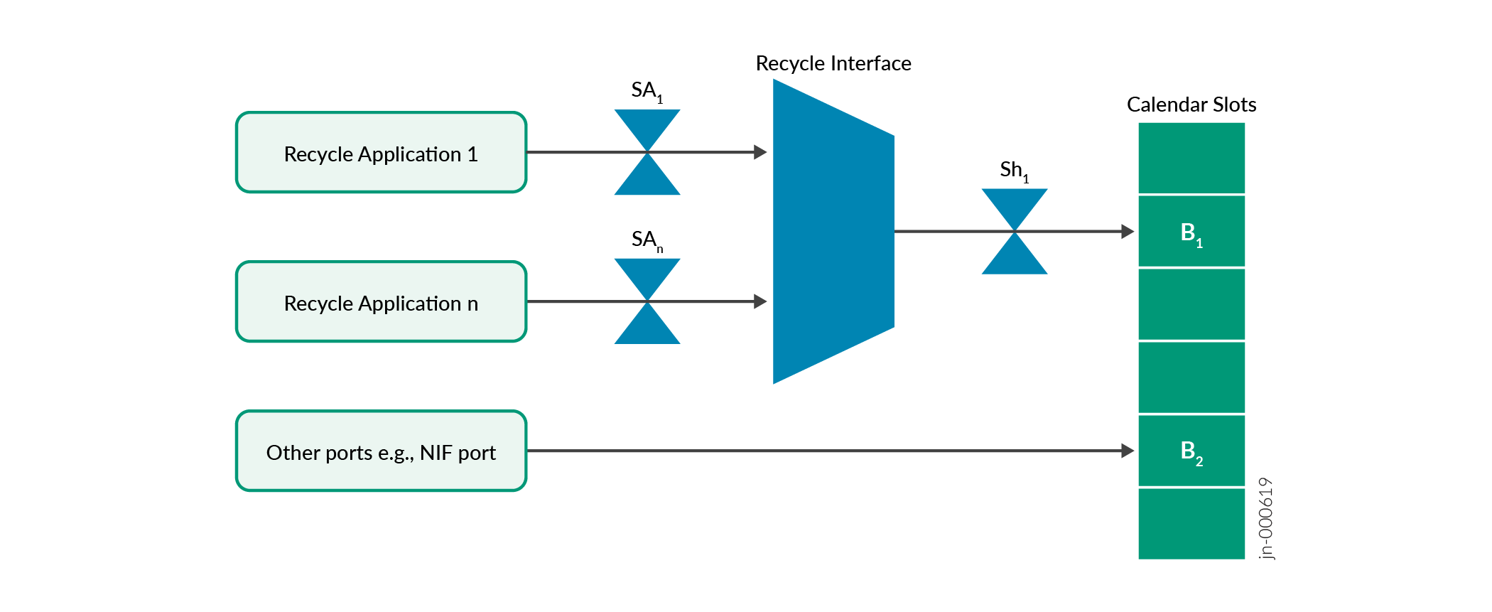
-
Sh1 – Recycle interface shaper
-
SA1 – Application #1 shaper over recycle channel 1
-
SAn – Application #n shaper over recycle channel n (max 256)
-
B1 – Calendar slot weight for traffic from the recycle interface. This reflects the calendar bandwidth value allocated to the recycle interface.
-
B2 – Calendar slot weight for traffic from interfaces other than the recycle interface. For example the NIF interface.
The recycle mechanism has two modes of operation:
-
Default Recycle Bandwidth Mode
-
Configurable Recycle Bandwidth Mode
Default Recycle Bandwidth Mode
Like the name suggests, the default recycle bandwidth mode is enabled by default and user configuration is not necessary. The recycle interface is allocated a set portion of the total calendar bandwidth. This recycle bandwidth is guaranteed and is therefore stable in times of traffic congestion. The recycle applications share this bandwidth on a best effort basis, which means there is no guaranteed bandwidth per application.
Benefits of default recycle bandwidth include:
-
Efficient utilization of recycle bandwidth. In case no recycle applications are running, the unused bandwidth can be shared among running applications from other interfaces.
-
Efficient utilization of chip bandwidth. In case the other interfaces other than the recycle interface are not carrying traffic, the unused bandwidth can be utilized by the recycle applications.
Configurable Recycle Bandwidth Mode
By configuring the recycle interface based on profiles, application bandwidth becomes manageable. You can guarantee allocation of recycle bandwidth for an application by defining it in a profile.
Benefits of configurable recycle bandwidth include:
-
Guaranteed bandwidth allocation for a defined recycle application.
-
Flexibility to change bandwidth allocation, which helps you to prioritize application bandwidth.
Example: Configuring Recycle Bandwidth
This example shows how to manage recycle bandwidth per application.
Overview
Aplications 1, 2, 3, and 4 are recycle applications that use the recycle interface. Table 1 shows our bandwidth requirements. In this case, we want guaranteed 10% allocation of the recycle interface bandwidth for application 1 and 20% for application 2. Applications 3 and 4 are not priority and no guarantee is necessary.
| Recycle Application | Required recycle bandwidth value in percentage |
|---|---|
| Application 1 | 10% |
| Application 2 | 20% |
| Application 3 | undefined |
| Application 4 | undefined |
Configure Recycle Interface Bandwidth
set system packet-forwarding-options recycle-bandwidth profile
                                profile1
set system packet-forwarding-options recycle-bandwidth-profile profile1 application1 10 application2 20
Verification
|
Command |
Verification Task |
|---|---|
|
|
From operational mode, run the |
Verifying recycle bandwidth per application
Purpose
Verifying recycle bandwidth allocation per application.
Action
user@router> show system packet-forwarding-options recycle-bandwidth-profile

Recycle Interface details:
Total Bandwidth :     300 Gbps/Core
PFE : 0
  Application-Name   | Core   | Bandwidth(Kbps) |  Port   |   VoQ  |  Profile
  -----------------------------------------------------------------------------
  application1           0        30000000           234       1336     profile1
  application2           0        60000000           242       1400     profile1
  application3           0        105000000          243       1408     profile1
  application4           0        105000000          245       1424     profile1
PFE : 1
  Application-Name   | Core   | Bandwidth(Kbps) |  Port   |   VoQ  |  Profile
  -----------------------------------------------------------------------------
  application1           0        30000000           234       2880     profile1
  application2           0        60000000           242       2944     profile1
  application3           0        105000000          243       2952     profile1
  application4           0        105000000          245       2968     profile1
Meaning
The output shows the recycle bandwidth allocation per application as configured in the section earlier.
| Application | Percentage configured | Result |
|---|---|---|
| application1 | 10 | 300 Gbps x 10% = 30 Gbps |
| application2 | 20 | 300 Gbps x 20% = 60 Gbps |
| application3 | not configured | Unutilized bandwidth/number of unconfigured recycle applications. (300 x 70%) / 2 = 105 Gbps |
| application4 | not configured | (300 x 70%) / 2 = 105 Gbps |