ON THIS PAGE
Example: Configuring Data MDTs and Provider Tunnels Operating in Any-Source Multicast Mode
This example shows how to configure data multicast distribution trees (MDTs) in a draft-rosen Layer 3 VPN operating in any-source multicast (ASM) mode. This example is based on the Junos OS implementation of RFC 4364, BGP/MPLS IP Virtual Private Networks (VPNs) and on section 2 of the IETF Internet draft draft-rosen-vpn-mcast-06.txt, Multicast in MPLS/BGP VPNs (expired April 2004).
Requirements
Before you begin:
Configure the draft-rosen multicast over Layer 3 VPN scenario.
Make sure that the routing devices support multicast tunnel (mt) interfaces.
A tunnel-capable PIC supports a maximum of 512 multicast tunnel interfaces. Both default and data MDTs contribute to this total. The default MDT uses two multicast tunnel interfaces (one for encapsulation and one for de-encapsulation). See "Tunnel Services PICs and Multicast” and "Load Balancing Multicast Tunnel Interfaces Among Available PICs” for further information on those topics.
Overview
By using data multicast distribution trees (MDTs) in a Layer 3 VPN, you can prevent multicast packets from being flooded unnecessarily to specified provider edge (PE) routers within a VPN group. This option is primarily useful for PE routers in your Layer 3 VPN multicast network that have no receivers for the multicast traffic from a particular source.
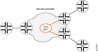
When a PE router that is directly connected to the multicast source (also called the source PE) receives Layer 3 VPN multicast traffic that exceeds a configured threshold, a new data MDT tunnel is established between the PE router connected to the source site and its remote PE router neighbors.
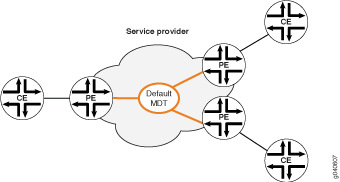
The source PE advertises the new data MDT group as long as the source is active. The periodic announcement is sent over the default MDT for the VRF. Because the data MDT announcement is sent over the default tunnel, all the PE routers receive the announcement.
Neighbors that do not have receivers for the multicast traffic cache the advertisement of the new data MDT group but ignore the new tunnel. Neighbors that do have receivers for the multicast traffic cache the advertisement of the new data MDT group and also send a PIM join message for the new group.
The source PE encapsulates the VRF multicast traffic using the new data MDT group and stops the packet flow over the default multicast tree. If the multicast traffic level drops back below the threshold, the data MDT is torn down automatically and traffic flows back across the default multicast tree.
If a PE router that has not yet joined the new data MDT group receives a PIM join message for a new receiver for which (S,G) traffic is already flowing over the data MDT in the provider core, then that PE router can obtain the new group address from its cache and can join the data-MDT immediately without waiting up to 59 seconds for the next data MDT advertisement.
By default, automatic creation of data MDTs is disabled.
For a rosen 6 MVPN—a draft-rosen multicast VPN with provider tunnels operating in ASM mode—you configure data MDT creation for a tunnel multicast group by including statements under the PIM protocol configuration for the VRF instance associated with the multicast group. Because data MDTs apply to VPNs and VRF routing instances, you cannot configure MDT statements in the master routing instance.
This example includes the following configuration options:
group—Specifies the multicast group address to which the threshold applies. This could be a well-known address for a certain type of multicast traffic.
The group address can be explicit (all 32 bits of the address specified) or a prefix (network address and prefix length specified). Explicit and prefix address forms can be combined if they do not overlap. Overlapping configurations, in which prefix and more explicit address forms are used for the same source or group address, are not supported.
group-range—Specifies the multicast group IP address range used when a new data MDT needs to be initiated on the PE router. For each new data MDT, one address is automatically selected from the configured group range.
The PE router implementing data MDTs for a local multicast source must be configured with a range of multicast group addresses. Group addresses that fall within the configured range are used in the join messages for the data MDTs created in this VRF instance. Any multicast address range can be used as the multicast prefix. However, the group address range cannot overlap the default MDT group address configured for any VPN on the router. If you configure overlapping group addresses, the configuration commit operation fails.
pim—Supports data MDTs for service provider tunnels operating in any-source multicast mode.
rate—Specifies the data rate that initiates the creation of data MDTs. When the source traffic in the VRF exceeds the configured data rate, a new tunnel is created. The range is from 10 kilobits per second (Kbps), the default, to 1 gigabit per second (Gbps, equivalent to 1,000,000 Kbps).
source—Specifies the unicast address of the source of the multicast traffic. It can be a source locally attached to or reached through the PE router. A group can have more than one source.
The source address can be explicit (all 32 bits of the address specified) or a prefix (network address and prefix length specified). Explicit and prefix address forms can be combined if they do not overlap. Overlapping configurations, in which prefix and more explicit address forms are used for the same source or group address, are not supported.
threshold—Associates a rate with a group and a source. The PE router implementing data MDTs for a local multicast source must establish a data MDT-creation threshold for a multicast group and source.
When the traffic stops or the rate falls below the threshold value, the source PE router switches back to the default MDT.
tunnel-limit—Specifies the maximum number of data MDTs that can be created for a single routing instance. The PE router implementing a data MDT for a local multicast source must establish a limit for the number of data MDTs created in this VRF instance. If the limit is 0 (the default), then no data MDTs are created for this VRF instance.
If the number of data MDT tunnels exceeds the maximum configured tunnel limit for the VRF, then no new tunnels are created. Traffic that exceeds the configured threshold is sent on the default MDT.
The valid range is from 0 through 1024 for a VRF instance. There is a limit of 8000 tunnels for all data MDTs in all VRF instances on a PE router.
Configuration
Procedure
CLI Quick Configuration
To quickly configure this example, copy the following commands, paste
them into a text file, remove any line breaks, change any details necessary to match your
network configuration, and then copy and paste the commands into the CLI at the [edit] hierarchy level.
[edit]
set routing-instances vpn-A protocols pim mdt group-range 227.0.0.0/8
set routing-instances vpn-A protocols pim mdt threshold group 224.4.4.4/32 source 10.10.20.43/32 rate 10
set routing-instances vpn-A protocols pim mdt tunnel-limit 10
Step-by-Step Procedure
The following example requires you to navigate various levels in the configuration hierarchy. For information about navigating the CLI, see Using the CLI Editor in Configuration Mode in the Junos OS CLI User Guide.
To configure a PE router attached to the VRF instance vpn-A in a PIM-ASM multicast VPN to initiate new data MDTs and provider tunnels for that VRF:
Configure the group range.
[edit]
user@host# edit routing-instances vpn-A protocols pim mdt
[edit routing-instances vpn-A protocols pim mdt]
user@host# set group-range 227.0.0.0/8
Configure a data MDT-creation threshold for a multicast group and source.
[edit routing-instances vpn-A protocols pim mdt]
user@host# set threshold group 224.4.4.4 source 10.10.20.43 rate 10
Configure a tunnel limit.
[edit routing-instances vpn-A protocols pim mdt]
user@host# set tunnel-limit 10
If you are done configuring the device, commit the configuration.
[edit routing-instances vpn-A protocols pim mdt]
user@host# commit
Verification
To display information about the default MDT and any data MDTs for the VRF instance vpn-A, use the show pim mdt instance ce1 detail operational mode command. This command displays either the outgoing tunnels (the tunnels initiated by the local PE router), the incoming tunnels (tunnels initiated by the remote PE routers), or both.
To display the data MDT group addresses cached by PE routers that participate in the VRF instance vpn-A, use the show pim mdt data-mdt-joins instance vpn-A operational mode command. The command displays the information cached from MDT join TLV packets received by all PE routers participating in the specified VRF instance.
You can trace the operation of data MDTs by including the mdt detail flag
in the [edit protocols pim traceoptions] configuration. When this flag is set,
all the mt interface-related activity is logged in trace files.


