Overview
Types of VPNs
A virtual private network (VPN) consists of two topological areas: the provider’s network and the customer’s network. The customer’s network is commonly located at multiple physical sites and is also private (non-Internet). A customer site would typically consist of a group of routers or other networking equipment located at a single physical location. The provider’s network, which runs across the public Internet infrastructure, consists of routers that provide VPN services to a customer’s network as well as routers that provide other services. The provider’s network connects the various customer sites in what appears to the customer and the provider to be a private network.
To ensure that VPNs remain private and isolated from other VPNs and from the public Internet, the provider’s network maintains policies that keep routing information from different VPNs separate. A provider can service multiple VPNs as long as its policies keep routes from different VPNs separate. Similarly, a customer site can belong to multiple VPNs as long as it keeps routes from the different VPNs separate.
The Junos® Operating System (Junos OS) provides several types of VPNs; you can choose the best solution for your network environment. Each of the following VPNs has different capabilities and requires different types of configuration:
Layer 2 VPNs
Implementing a Layer 2 VPN on a router is similar to implementing a VPN using other Layer 2 technologies. However, for a Layer 2 VPN on a router, traffic is forwarded to the router in Layer 2 format. It is carried by MPLS over the service provider’s network and then converted back to a Layer 2 format at the receiving site. You can configure different Layer 2 formats at the sending and receiving sites.
On a Layer 2 VPN, routing occurs on the customer’s routers, typically on the CE router. The CE router connected to a service provider on a Layer 2 VPN must select the appropriate circuit on which to send traffic. The PE router receiving the traffic sends it across the service provider’s network to the PE router connected to the receiving site. The PE routers do not need to store or process the customer’s routes; they only need to be configured to send data to the appropriate tunnel.
For a Layer 2 VPN, customers need to configure their own routers to carry all Layer 3 traffic. The service provider needs to know only how much traffic the Layer 2 VPN needs to carry. The service provider’s routers carry traffic between the customer’s sites using Layer 2 VPN interfaces. The VPN topology is determined by policies configured on the PE routers.
Layer 3 VPNs
In a Layer 3 VPN, the routing occurs on the service provider’s routers. Therefore, Layer 3 VPNs require more configuration on the part of the service provider, because the service provider’s PE routers must store and process the customer’s routes.
In the Junos OS, Layer 3 VPNs are based on RFC 4364, BGP/MPLS IP Virtual Private Networks (VPNs). This RFC defines a mechanism by which service providers can use their IP backbones to provide Layer 3 VPN services to their customers. The sites that make up a Layer 3 VPN are connected over a provider’s existing public Internet backbone.
VPNs based on RFC 4364 are also known as BGP/MPLS VPNs because BGP is used to distribute VPN routing information across the provider’s backbone, and MPLS is used to forward VPN traffic across the backbone to remote VPN sites.
Customer networks, because they are private, can use either public addresses or private addresses, as defined in RFC 1918, Address Allocation for Private Internets. When customer networks that use private addresses connect to the public Internet infrastructure, the private addresses might overlap with the private addresses used by other network users. BGP/MPLS VPNs solve this problem by prefixing a VPN identifier to each address from a particular VPN site, thereby creating an address that is unique both within the VPN and within the public Internet. In addition, each VPN has its own VPN-specific routing table that contains the routing information for that VPN only.
VPLS
Virtual private LAN service (VPLS) allows you to connect geographically dispersed customer sites as if they were connected to the same LAN. In many ways, it works like a Layer 2 VPN. VPLS and Layer 2 VPNs use the same network topology and function similarly. A packet originating within a customer’s network is sent first to a CE device. It is then sent to a PE router within the service provider’s network. The packet traverses the service provider’s network over an MPLS LSP. It arrives at the egress PE router, which then forwards the traffic to the CE device at the destination customer site.
The key difference in VPLS is that packets can traverse the service provider’s network in a point-to-multipoint fashion, meaning that a packet originating from a CE device can be broadcast to PE routers in the VPLS. In contrast, a Layer 2 VPN forwards packets in a point-to-point fashion only. The destination of a packet received from a CE device by a PE router must be known for the Layer 2 VPN to function properly.
In a Layer 3 network only, you can configure virtual private LAN service (VPLS), to connect geographically dispersed Ethernet local area networks (LAN) sites to each other across an MPLS backbone. For ISP customers who implement VPLS, all sites appear to be in the same Ethernet LAN even though traffic travels across the service provider's network. VPLS is designed to carry Ethernet traffic across an MPLS-enabled service provider network. In certain ways, VPLS mimics the behavior of an Ethernet network. When a PE router configured with a VPLS routing instance receives a packet from a CE device, it first checks the appropriate routing table for the destination of the VPLS packet. If the router has the destination, it forwards it to the appropriate PE router. If it does not have the destination, it broadcasts the packet to all the other PE routers that are members of the same VPLS routing instance. The PE routers forward the packet to their CE devices. The CE device that is the intended recipient of the packet forwards it to its final destination. The other CE devices discard it.
Virtual-Router Routing Instances
A virtual-router
routing instance, like a VPN routing and forwarding (VRF) routing
instance, maintains separate routing and forwarding tables for each
instance. However, many configuration steps required for VRF routing
instances are not required for virtual-router routing instances. Specifically,
you do not need to configure a route distinguisher, a routing table
policy (the vrf-export, vrf-import, and route-distinguisher statements), or MPLS between the P routers.
However, you need to configure separate logical interfaces between each of the service provider routers participating in a virtual-router routing instance. You also need to configure separate logical interfaces between the service provider routers and the customer routers participating in each routing instance. Each virtual-router instance requires its own unique set of logical interfaces to all participating routers.
Figure 1 shows how this works. The service provider routers G and H are configured for virtual-router routing instances Red and Green. Each service provider router is directly connected to two local customer routers, one in each routing instance. The service provider routers are also connected to each other over the service provider network. These routers need four logical interfaces: a logical interface to each of the locally connected customer routers and a logical interface to carry traffic between the two service provider routers for each virtual-router instance.
Layer 3 VPNs do not have this configuration requirement. If you configure several Layer 3 VPN routing instances on a PE router, all the instances can use the same logical interface to reach another PE router. This is possible because Layer 3 VPNs use MPLS (VPN) labels that differentiate traffic going to and from various routing instances. Without MPLS and VPN labels, as in a virtual-router routing instance, you need separate logical interfaces to separate traffic from different instances.
One method of providing this logical interface between the service provider routers is by configuring tunnels between them. You can configure IP Security (IPsec), generic routing encapsulation (GRE), or IP-IP tunnels between the service provider routers, terminating the tunnels at the virtual-router instance.
VPNs and Logical Systems
You can partition a single physical router into multiple logical systems that perform independent routing tasks. Because logical systems perform a subset of the tasks once handled by the physical router, logical systems offer an effective way to maximize the use of a single routing platform.
Logical systems perform a subset of the actions of a physical router and have their own unique routing tables, interfaces, policies, and routing instances. A set of logical systems within a single router can handle the functions previously performed by several small routers.
Logical systems support Layer 2 VPNs, Layer 3 VPNs, VPLS, and Layer 2 circuits. For more information about logical systems, see the Logical Systems User Guide for Routers and Switches.
Ethernet VPN (EVPN) support has also been extended to logical systems running on MX devices. The
same EVPN options and performance are available, and can be configured under the
[edit logical-systems logical-system-name
                routing-instances routing-instance-name protocols evpn]
hierarchy.
Understanding Layer 3 VPNs
Virtual private networks (VPNs) are private networks that use a public network to connect two or more remote sites. Instead of dedicated connections between networks, VPNs use virtual connections routed (tunneled) through public networks that are typically service provider networks.
Layer 3 VPN operates at the Layer 3 level of the OSI model, the Network layer. A Layer 3 VPN is composed of a set of customer sites that are connected over a service provider's existing public Internet backbone. A peer-to-peer model is used to connect to the customer sites, where the service providers learn the customer routes on peering with the customers. The common routing information is shared across the provider's backbone using multiprotocol BGP, and the VPN traffic is forwarded to the customer sites using MPLS.
Junos OS supports Layer 3 VPNs based on RFC 4364. The RFC describes VPNs using MPLS tunnels for connectivity, BGP to distribute reachability information, and an IP backbone for transport. Service providers use their IP backbones to link a set of customer sites belonging to the same VPN.
Components of a Layer 3 VPN
There are three primary types of MPLS VPNs: Layer 2 VPNs, Layer 2 circuits, and Layer 3 VPNs. All types of MPLS VPNs share certain components:
-
CE devices—Customer Edge (CE) devices at the customer premises that connect to the provider’s network. Some models call these Customer Premises Equipment (CPE) devices.
-
Customer network—Customer sites with CE devices that belong to the VPN.
-
Provider network—The service provider backbone network running the MPLS backbone.
-
P devices—Provider (P) devices within the core of the provider’s network. Provider devices are not connected to any device at a customer site and are part of the tunnel between pairs of PE devices. Provider devices support label-switched path (LSP) functionality as part of the tunnel support, but do not support VPN functionality.
-
PE devices—Provider Edge (PE) devices within a service provider core network that connect directly to a CE device at the customer's site.
-
MP-BGP— PE devices use MP-BGP to distribute customer routes to the proper PE devices across the MPLS backbone.
Layer 3 VPN Terminology
VPNs use a distinct terminology to identify components of the network:
-
IP routing table (also called the global routing table)—This table contains service provider routes not included in a VRF. Provider devices need this table to be able to reach each other, while the VRF table is needed to reach all customer devices on a particular VPN. For example, a PE router with Interface A to a CE router and Interface B to a backbone P router places the Interface A addresses in the VRF and the Interface B addresses in the global IP routing table.
-
Route Distinguisher—A 64-bit value prepended to an IP address. This unique tag helps identify the different customers’ routes as packets flow across the same service provider tunnel.
Because a typical transit network is configured to handle more than one VPN, the provider routers are likely to have multiple VRF instances configured. As a result, depending on the origin of the traffic and any filtering rules applied to the traffic, the BGP routing tables can contain multiple routes for a particular destination address. Because BGP requires that exactly one BGP route per destination to be imported into the forwarding table, BGP must have a way to distinguish between potentially identical network layer reachability information (NLRI) messages received from different VPNs.
A route distinguisher is a locally unique number that identifies all route information for a particular VPN. Unique numeric identifiers allow BGP to distinguish between routes that are otherwise identical.
Each routing instance that you configure on a PE router must have a unique route distinguisher. There are two possible formats:
-
as-number:number—Where, as-number is an autonomous system (AS) number (a 2–byte value) in the range 1 through 65,535, and number is any 4–byte value. We recommend that you use an Internet Assigned Numbers Authority (IANA)-assigned, nonprivate AS number, preferably the ISP or the customer AS number.
-
ip-address:number—Where, ip-address is an IP address (a 4–byte value), and number is any 2–byte value. The IP address can be any globally unique unicast address. We recommend that you use the address that you configure in the router-id statement, which is a public IP address in your assigned prefix range.
-
-
Route Target (RT)—A 64-bit value used to identify the final egress PE device for customer routes in a particular VRF to enable complex sharing of routes. The route target defines which route is part of a VPN. A unique route target helps distinguish between different VPN services on the same router. Each VPN also has a policy that defines how routes are imported into the VRF table on the router. A Layer 2 VPN is configured with import and export policies. A Layer 3 VPN uses a unique route target to distinguish between VPN routes. For example, the RT enables the sharing of routes in a shared service network to multiple customers. Each VPN route can have one or more RTs. A PE device handles RTs as extended BGP community values and uses the RTs to install customer routes.
-
VPN-IPv4 routes—A route consisting of a 96-bit sequence composed of a 64-bit RD tag prepended to a 32-bit IPv4 address. The PE devices export the VPN-IPv4 routes in IBGP sessions to the other provider devices.These routes are exchanged across the MPLS backbone using iBGP. When the outbound PE device receives the route, it strips off the route distinguisher and advertises the route to the connected CE devices, typically through standard BGP IPv4 route advertisements.
-
VRF—The virtual routing and forwarding (VRF) table distinguishes the routes for different customers, as well as customer routes from provider routes on the PE device. These routes can include overlapping private network address spaces, customer-specific public routes, and provider routes on a PE device useful to the customer.
A VRF instance consists of one or more routing tables, a derived forwarding table, the interfaces that use the forwarding table, and the policies and routing protocols that determine what goes into the forwarding table. Because each instance is configured for a particular VPN, each VPN has separate tables, rules, and policies that control its operation.
A separate VRF table is created for each VPN that has a connection to a CE router. The VRF table is populated with routes received from directly connected CE sites associated with the VRF instance, and with routes received from other PE routers in the same VPN.
Layer 3 VPN Architecture
A Layer 3 VPN links customer-edge routers (CE routers) to routers on the edge of the service provider network (PE routers). A Layer 3 VPN uses a peer routing model between local PE and CE routers that directly connect. That is, without needing multiple hops on the provider backbone to connect PE and CE router pairs. The PE routers distribute routing information to all CE routers belonging to the same VPN, based on the BGP route distinguisher, locally and across the provider network. Each VPN has its own routing table for that VPN, coordinated with the routing tables in the CE and PE peer routers. The CE and PE routers have different VRF tables. Each CE router has only a single VRF table because the other VPNs are invisible to the CE. A PE router can connect to more than one CE router, so the PE router has a general IP routing table and VRF table for each attached CE with a VPN.
Figure 2 shows the general architecture of a Layer 3 VPN.
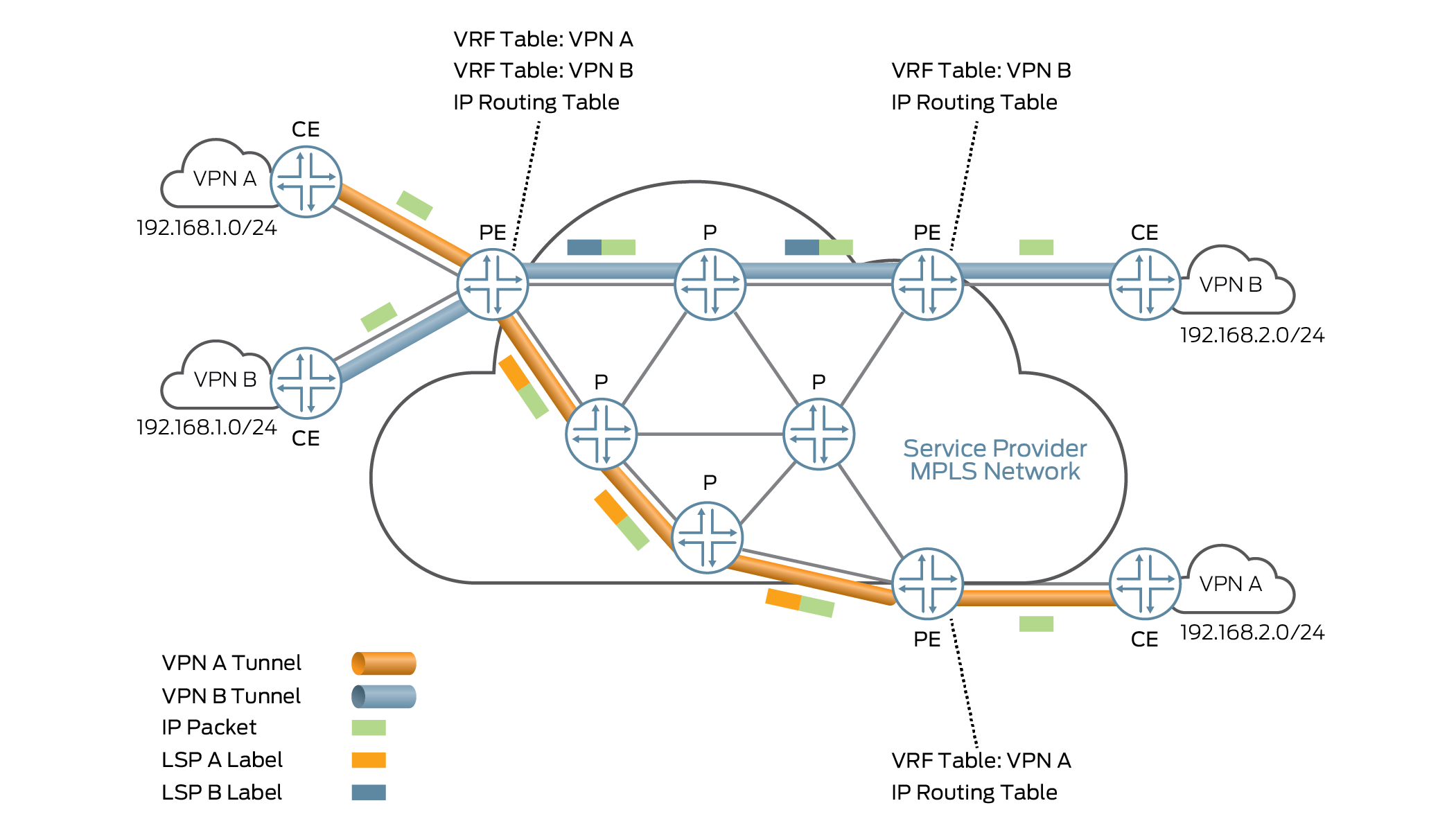
The PE router knows which VRF table to use for packets arriving from remote VPN sites because every VRF table has one or more extended community attributes associated with hit. The community attributes identify the route as belonging to a specific collection of routers. The route target community attribute identifies a collection of sites (more accurately, the collection of their VRF tables) to which a PE router distributes routes. The PE router uses the route target to import the correct remote VPN routes into its VRF tables.
The import and export of VPN routes between VPN sites is not automatic. This process is controlled by BPG routing polices. The routing policies establish the rules for exchanging routing information across the service provider’s MPLS network and must be configured correctly and maintained when the network topology changes.
The PE router classifies IPv4 routes announced by a peer CE router and received by the PE router as VPN-IPv4 routes. When an ingress PE router receives routes advertised from a directly connected peer CE router, the ingress PE router checks the received route against the VRF export policy for that VPN. That is, the ingress PE router decides which remote PE routers need to know about the advertised routes. This is a two-step process:
-
If the established export policy accepts the route, the PE router converts the information to VPN-IPv4 format by adding the route distinguisher to the IPv4 address. The PE router then announces the VPN-IPv4 route to the remote PE routers. The configured export target policy of the VRF table determines the value of the attached route target. IBGP sessions distribute the VNP-IPv4 routes across the service provider’s core network.
-
If the established export policy does not accept the route, the PE router does not export the route to other PE routers, but the PE router uses the route locally. This happens, for example, when two CE routers in the same VPN connect directly to the same PE router so general traffic can flow from one CE site to another.
When an egress PE router on the other side of the service provider network receives a route, the egress PE router checks the route against the IBGP import policy in place between the PE routers. If the egress PE router accepts the route, then the egress PE router adds the route to the bgp.l3vpn.0 routing table. The router also checks the route against the VRF import policy for the VPN. If the route is accepted, the egress PE router removes the route distinguisher and places the route into the correct VRF table. The VRF tables use the routing-instance-name.inet.0 naming convention, so “VPN A” usually configures the table as vpna.inet.0).
Supported Layer 3 VPN Standards
Junos OS substantially supports the following RFCs, which define standards for Layer 3 virtual private networks (VPNs).
RFC 2283, Multiprotocol Extensions for BGP-4
RFC 2685, Virtual Private Networks Identifier
RFC 2858, Multiprotocol Extensions for BGP-4
RFC 4364, BGP/MPLS IP Virtual Private Networks (VPNs)
RFC 4379, Detecting Multi-Protocol Label Switched (MPLS) Data Plane Failures
The traceroute functionality is supported only on transit routers.
RFC 4576, Using a Link State Advertisement (LSA) Options Bit to Prevent Looping in BGP/MPLS IP Virtual Private Networks (VPNs)
RFC 4577, OSPF as the Provider/Customer Edge Protocol for BGP/MPLS IP Virtual Private Networks (VPNs)
RFC 4659, BGP-MPLS IP Virtual Private Network (VPN) Extension for IPv6 VPN
RFC 4684, Constrained Route Distribution for Border Gateway Protocol/MultiProtocol Label Switching (BGP/MPLS) Internet Protocol (IP) Virtual Private Networks (VPNs)
The following RFCs do not define a standard, but provide information about technology related to Layer 3 VPNs. The IETF classifies them as a “Best Current Practice” or “Informational.”
RFC 1918, Address Allocation for Private Internets
RFC 2917, A Core MPLS IP VPN Architecture
See Also
Understanding Layer 3 VPN Forwarding Through the Core
The PE routers in the provider’s core network are the only routers that are configured to support VPNs and hence are the only routers to have information about the VPNs. From the point of view of VPN functionality, the provider (P) routers in the core—those P routers that are not directly connected to CE routers—are merely routers along the tunnel between the ingress and egress PE routers.
The tunnels can be either LDP or MPLS. Any P routers along the tunnel must support the protocol used for the tunnel, either LDP or MPLS.
When PE-router-to-PE router forwarding is tunneled over MPLS label-switched paths (LSPs), the MPLS packets have a two-level label stack (see Figure 3):
-
Outer label—Label assigned to the address of the BGP next hop by the IGP next hop
-
Inner label—Label that the BGP next hop assigned for the packet’s destination address
Figure 4 illustrates how the labels are assigned and removed:
-
When CE Router X forwards a packet to Router PE1 with a destination of CE Router Y, the PE route identifies the BGP next hop to Router Y and assigns a label that corresponds to the BGP next hop and identifies the destination CE router. This label is the inner label.
-
Router PE1 then identifies the IGP route to the BGP next hop and assigns a second label that corresponds to the LSP of the BGP next hop. This label is the outer label.
-
The inner label remains the same as the packet traverses the LSP tunnel. The outer label is swapped at each hop along the LSP and is then popped by the penultimate hop router (the third P router).
-
Router PE2 pops the inner label from the route and forwards the packet to Router Y.
Understanding Layer 3 VPN Attributes
Route distribution within a VPN is controlled through BGP extended community attributes. RFC 4364 defines the following three attributes used by VPNs:
-
Target VPN—Identifies a set of sites within a VPN to which a provider edge (PE) router distributes routes. This attribute is also called the route target. The route target is used by the egress PE router to determine whether a received route is destined for a VPN that the router services.
Figure 5 illustrates the function of the route target. PE Router PE1 adds the route target “VPN B” to routes received from the customer edge (CE) router at Site 1 in VPN B. When it receives the route, the egress router PE2 examines the route target, determines that the route is for a VPN that it services, and accepts the route. When the egress router PE3 receives the same route, it does not accept the route because it does not service any CE routers in VPN B.
-
VPN of origin—Identifies a set of sites and the corresponding route as having come from one of the sites in that set.
-
Site of origin—Uniquely identifies the set of routes that a PE router learned from a particular site. This attribute ensures that a route learned from a particular site through a particular PE-CE connection is not distributed back to the site through a different PE-CE connection. It is particularly useful if you are using BGP as the routing protocol between the PE and CE routers and if different sites in the VPN have been assigned the same autonomous system (AS) numbers.
Routers in a VPN
Figure 6 illustrates how VPN functionality is provided by the provider edge (PE) routers; the provider and customer edge (CE) routers have no special configuration requirements for VPNs.
Introduction to Configuring Layer 3 VPNs
To configure Layer 3 virtual private network (VPN) functionality, you must enable VPN support on the provider edge (PE) router. You must also configure any provider (P) routers that service the VPN, and you must configure the customer edge (CE) routers so that their routes are distributed into the VPN.
To configure Layer 3 VPNs, you include the following statements:
description text;
instance-type vrf;
interface interface-name;
protocols {
    bgp {
        group group-name {
            peer-as as-number;
            neighbor ip-address;
        }
        multihop ttl-value;
    }
    (ospf | ospf3) {
        area area {
            interface interface-name;
        }
        domain-id domain-id;
        domain-vpn-tag number;
        sham-link {
            local address;
        }
        sham-link-remote address <metric number>;
    }
    rip {
        rip-configuration;
    }
}
route-distinguisher (as-number:id | ip-address:id);
router-id address;
routing-options {
    autonomous-system autonomous-system {
        independent-domain;
        loops number;
    }
    forwarding-table {
        export [ policy-names ];
    }
    interface-routes {
        rib-group group-name;
    }
    martians {
        destination-prefix match-type <allow>;
    }
    maximum-paths {
        path-limit;
        log-interval interval;
        log-only;
        threshold percentage;
    }
    maximum-prefixes {
        prefix-limit;
        log-interval interval;
        log-only;
        threshold percentage;
    }
    multipath {
        vpn-unequal-cost;
    }
    options {
        syslog (level level | upto level);
    }
    rib routing-table-name {
        martians {
            destination-prefix match-type <allow>;
        }
        multipath {
            vpn-unequal-cost;
        }
        static {
            defaults {
                static-options;
            }
            route destination-prefix {
                next-hop [next-hops];
                static-options;
            }
        }
    }
}
static {
    defaults {
        static-options;
    }
    route destination-prefix {
        policy [ policy-names ];
        static-options;
    }
}
vrf-advertise-selective {
    family {
        inet-mvpn;
        inet6-mvpn;
    }
}
vrf-export [ policy-names ];
vrf-import [ policy-names ];
vrf-target (community | export community-name | import community-name);
vrf-table-label;
You can include these statements at the following hierarchy levels:
[edit routing-instances routing-instance-name][edit logical-systems logical-system-name routing-instances routing-instance-name]
The [edit logical-systems] hierarchy level
is not applicable in ACX Series routers.
The sham-link, sham-link-remote, and vrf-advertise-selective statements are not applicable in ACX
Series routers.
For Layer 3 VPNs, only some of the statements in the [edit routing-instances] hierarchy are valid. For the full
hierarchy, see Junos OS Routing Protocols
Library.
In addition to these statements, you must enable a signaling protocol, IBGP sessions between the PE routers, and an interior gateway protocol (IGP) on the PE and P routers.
By default, Layer 3 VPNs are disabled.
Many of the configuration procedures for Layer 3 VPNs are common to all types of VPNs.
Change History Table
Feature support is determined by the platform and release you are using. Use Feature Explorer to determine if a feature is supported on your platform.
[edit logical-systems logical-system-name routing-instances routing-instance-name protocols evpn] hierarchy.