Layer 2 Interfaces on Security Devices
Understanding Layer 2 Interfaces on Security Devices
Layer 2 logical interfaces are created by defining one or more logical units on a physical interface with the family address type ethernet-switching. If a physical interface has a ethernet-switching family logical interface, it cannot have any other family type in its logical interfaces. A logical interface can be configured in one of the following modes:
Access mode—Interface accepts untagged packets, assigns the specified VLAN identifier to the packet, and forwards the packet within the VLAN that is configured with the matching VLAN identifier.
Trunk mode—Interface accepts any packet tagged with a VLAN identifier that matches a specified list of VLAN identifiers. Trunk mode interfaces are generally used to interconnect switches. To configure a VLAN identifier for untagged packets received on the physical interface, use the
native-vlan-idoption. If thenative-vlan-idoption is not configured, untagged packets are dropped.
Multiple trunk mode logical interfaces can be defined,
as long as the VLAN identifiers of a trunk interface do not overlap
with those of another trunk interface. The native-vlan-id must belong to a VLAN identifier list configured for a trunk interface.
See Also
Example: Configuring Layer 2 Logical Interfaces on Security Devices
This example shows how to configure a Layer 2 logical interface as a trunk port so that the incoming packets can be selectively redirected to a firewall or other security device.
Requirements
Before you begin, configure the VLANs. See Example: Configuring VLANs on Security Devices.
Overview
In this example, you configure logical interface ge-3/0/0.0 as a trunk port that carries traffic for packets tagged with VLAN identifiers 1 through 10; this interface is implicitly assigned to the previously configured VLANs vlan-a and vlan-b. Then you assign a VLAN ID of 10 to any untagged packets received on physical interface ge-3/0/0.
Configuration
CLI Quick Configuration
To quickly configure this example, copy the
following commands, paste them into a text file, remove any line breaks,
change any details necessary to match your network configuration,
copy and paste the commands into the CLI at the [edit] hierarchy
level, and then enter commit from configuration mode.
set interfaces ge-3/0/0 unit 0 family ethernet-switching interface-mode trunk vlan members 1–10
set interfaces ge-3/0/0 vlan-tagging native-vlan-id 10
Procedure
Step-by-Step Procedure
The following example requires you to navigate various levels in the configuration hierarchy. For instructions on how to do that, see Using the CLI Editor in Configuration Mode in the CLI User Guide.
To configure a Layer 2 logical interface as a trunk port:
Configure the logical interface.
[edit interfaces ge-3/0/0]
user@host# set unit 0 family ethernet-switching interface-mode trunk vlan members 1–10
Specify a VLAN ID for untagged packets.
[edit interfaces ge-3/0/0]
user@host# set vlan-tagging native-vlan-id 10
If you are done configuring the device, commit the configuration.
[edit]
user@host# commit
Verification
To verify the configuration is working properly,
enter the show interfaces ge-3/0/0 and show interfaces
ge-3/0/0.0 commands.
Understanding Mixed Mode (Transparent and Route Mode) on Security Devices
Mixed mode supports both transparent mode (Layer 2) and route mode (Layer 3). You can configure both Layer 2 and Layer 3 interfaces simultaneously using separate security zones.
For the mixed mode configuration, you must reboot the device after you commit the changes. However, for SRX5000 line devices, reboot is not required.
SRX4100 and SRX4200 devices support logical system in both transparent and route mode
SRX4600 device supports logical system in route mode only
In mixed mode (Transparent and Route Mode):
-
There is no routing among IRB interfaces and between IRB interfaces and Layer 3 interfaces.
The device in Figure 1 looks like two separate devices. One device runs in Layer 2 transparent mode and the other device runs in Layer 3 routing mode. But both devices run independently. Packets cannot be transferred between the Layer 2 and Layer 3 interfaces, because there is no routing among IRB interfaces and between IRB interfaces and Layer 3 interfaces.
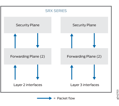
In mixed mode, the Ethernet physical interface can be either a Layer 2 interface or a Layer 3 interface, but the Ethernet physical interface cannot be both simultaneously. However, Layer 2 and Layer 3 families can exist on separate physical interfaces on the same device.
Table 1 lists the Ethernet physical interface types and supported family types.
|
Ethernet Physical Interface Type |
Supported Family Type |
|---|---|
|
Layer 2 Interface |
|
|
Layer 3 Interface |
|
Multiple routing instances are supported.
You can configure both the pseudointerface irb.x and
the Layer 3 interface under the same default routing instance using
either a default routing instance or a user-defined routing instance.
See Figure 2.
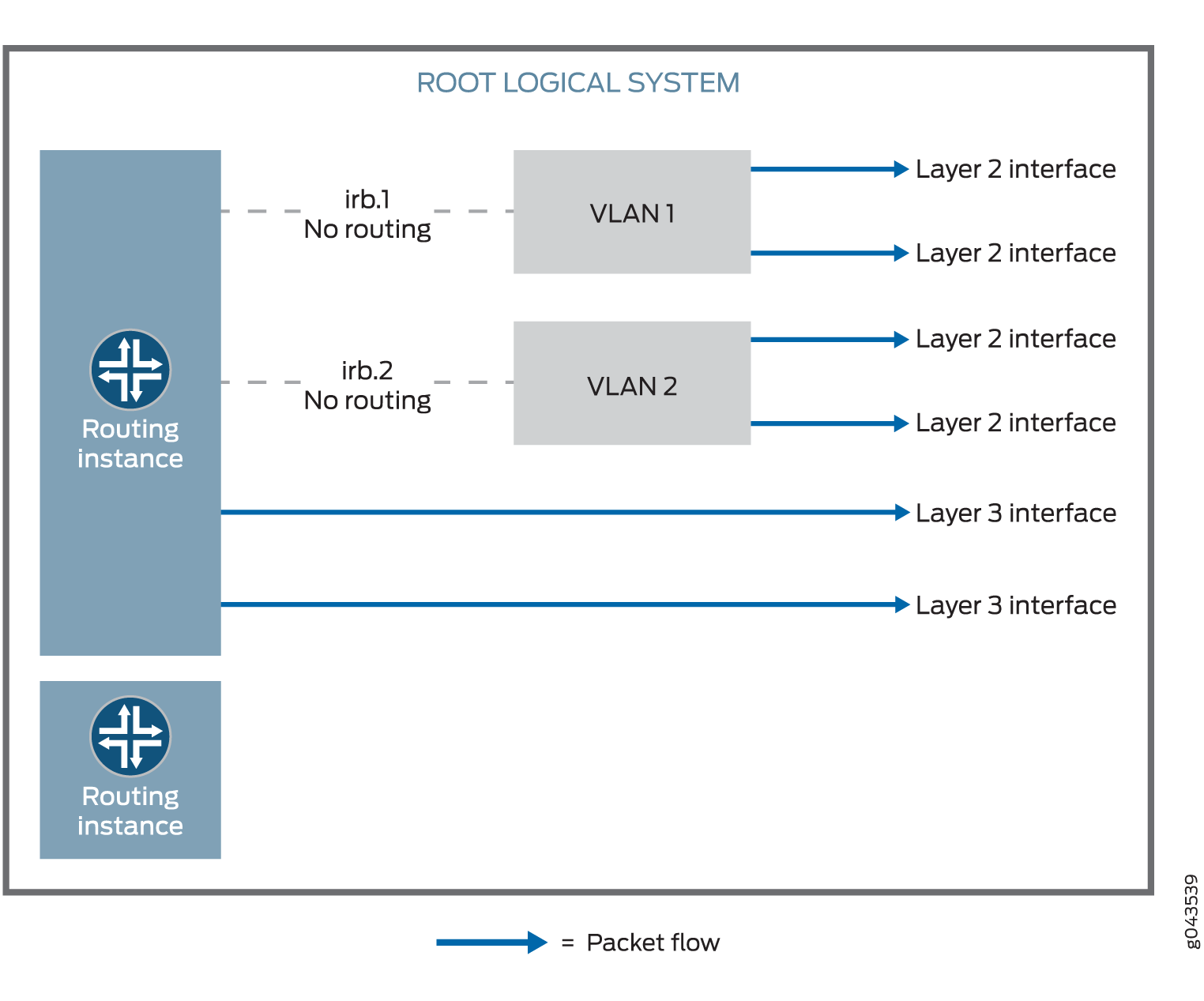
Packets from the Layer 2 interface are switched within the same VLAN, or they connect to the host through the IRB interface. Packets cannot be routed to another IRB interface or a Layer 3 interface through their own IRB interface.
Packets from the Layer 3 interface are routed to another Layer 3 interface. Packets cannot be routed to a Layer 2 interface through an IRB interface.
Table 2 lists the security features that are supported in mixed mode and the features that are not supported in transparent mode for Layer 2 switching.
|
Mode Type |
Supported |
Not Supported |
|---|---|---|
|
Mixed mode |
|
— |
|
Route mode (Layer 3 interface) |
|
— |
|
Transparent mode (Layer 2 interface) |
|
|
Starting in Junos OS Release 12.3X48-D10 and Junos OS Release 17.3R1, some conditions apply to mixed-mode operations. Note the conditions here:
-
On SRX300, SRX320, SRX340, SRX345, SRX380, SRX550, SRX550HM, and SRX1500 devices, you cannot configure Ethernet switching and virtual private LAN service (VPLS) using mixed mode (Layer 2 and Layer 3).
-
On SRX5400, SRX5600, and SRX5800 devices, you do not have to reboot the device when you configure VLAN.
See Also
Example: Improving Security Services by Configuring an SRX Series Firewall Using Mixed Mode (Transparent and Route Mode)
You can configure an SRX Series Firewall using both transparent mode (Layer 2) and route mode (Layer 3) simultaneously to simplify deployments and to improve security services.
This example shows how to pass the Layer 2 traffic from interface ge-0/0/1.0 to interface ge-0/0/0.0 and Layer 3 traffic from interface ge-0/0/2.0 to interface ge-0/0/3.0.
Requirements
This example uses the following hardware and software components:
An SRX Series Firewall
Four PCs
Before you begin:
Create a separate security zone for Layer 2 and Layer 3 interfaces. See Understanding Layer 2 Security Zones.
Overview
In enterprises where different business groups have either Layer 2 or Layer 3 based security solutions, using a single mixed mode configuration simplifies their deployments. In a mixed mode configuration, you can also provide security services with integrated switching and routing.
In addition, you can configure an SRX Series Firewall in both standalone and chassis cluster mode using mixed mode.
In mixed mode, you can configure both Layer 2 and Layer 3 interfaces simultaneously using separate security zones.
For the mixed mode configuration, you must reboot the device after you commit the changes. However, for SRX5000 line devices, reboot is not required.
In this example, first you configure a Layer 2 family type called Ethernet switching to identify Layer 2 interfaces. You set the IP address 10.10.10.1/24 to IRB interface. Then you create zone L2 and add Layer 2 interfaces ge-0/0/1.0 and ge-0/0/0.0 to it.
Next you configure a Layer 3 family type inet to identify Layer 3 interfaces. You set the IP address 192.0.2.1/24 to interface ge-0/0/2.0 and the IP address 192.0.2.3/24 to interface ge-0/0/3. Then you create zone L3 and add Layer 3 interfaces ge-0/0/2.0 and ge-0/0/3.0 to it.
Topology
Figure 3 shows a mixed mode topology.
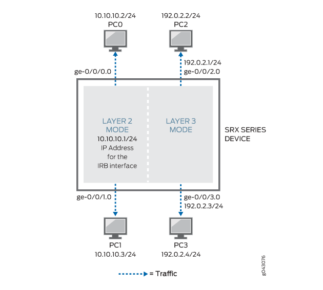
Table 3 shows the parameters configured in this example.
Parameter |
Description |
|---|---|
L2 |
Layer 2 zone. |
ge-0/0/1.0 and ge-0/0/0.0 |
Layer 2 interfaces added to the Layer 2 zone. |
L3 |
Layer 3 zone. |
ge-0/0/2.0 and ge-0/0/3.0 |
Layer 3 interfaces added to the Layer 3 zone. |
10.10.10.1/24 |
IP address for the IRB interface. |
192.0.2.1/24 and 192.0.2.3/24 |
IP addresses for the Layer 3 interface. |
Configuration
Procedure
CLI Quick Configuration
To quickly configure this example, copy the
following commands, paste them into a text file, remove any line breaks,
change any details necessary to match your network configuration,
copy and paste the commands into the CLI at the [edit] hierarchy
level, and then enter commit from configuration mode.
set interfaces ge-0/0/0 unit 0 family ethernet-switching interface-mode access
set interfaces ge-0/0/0 unit 0 family ethernet-switching vlan members 10
set interfaces ge-0/0/1 unit 0 family ethernet-switching interface-mode access
set interfaces ge-0/0/1 unit 0 family ethernet-switching vlan members 10
set protocols l2-learning global-mode transparent-bridge
set interfaces irb unit 10 family inet address 10.10.10.1/24
set security zones security-zone L2 interfaces ge-0/0/1.0
set security zones security-zone L2 interfaces ge-0/0/0.0
set vlans vlan-10 vlan-id 10
set vlans vlan-10 l3-interface irb.10
set interfaces ge-0/0/2 unit 0 family inet address 192.0.2.1/24
set interfaces ge-0/0/3 unit 0 family inet address 192.0.2.3/24
set security policies default-policy permit-all
set security zones security-zone L2 host-inbound-traffic system-services any-service
set security zones security-zone L2 host-inbound-traffic protocols all
set security zones security-zone L3 host-inbound-traffic system-services any-service
set security zones security-zone L3 host-inbound-traffic protocols all
set security zones security-zone L3 interfaces ge-0/0/2.0
set security zones security-zone L3 interfaces ge-0/0/3.0
Step-by-Step Procedure
The following example requires you to navigate various levels in the configuration hierarchy. For instructions on how to do that, see Using the CLI Editor in Configuration Mode in the CLI User Guide.
To configure Layer 2 and Layer 3 interfaces:
Create a Layer 2 family type to configure Layer 2 interfaces.
[edit interfaces]
user@host# set ge-0/0/0 unit 0 family ethernet-switching interface-mode access
user@host# set ge-0/0/0 unit 0 family ethernet-switching vlan members 10
user@host# set ge-0/0/1 unit 0 family ethernet-switching interface-mode access
user@host# set ge-0/0/1 unit 0 family ethernet-switching vlan members 10
Configure Layer 2 interfaces to work under transparent-bridge mode.
[edit protocols]
user@host# set l2-learning global-mode transparent-bridge
Configure an IP address for the IRB interface.
[edit interfaces]
user@host# set irb unit 10 family inet address 10.10.10.1/24
Configure Layer 2 interfaces.
[edit security zones security-zone L2 interfaces]
user@host# set ge-0/0/1.0
user@host#  set ge-0/0/0.0
Configure VLAN.
[edit vlans vlan-10]
user@host# set vlan-id 10
user@host# set l3-interface irb.10
Configure IP addresses for Layer 3 interfaces.
[edit interfaces]
user@host# set ge-0/0/2 unit 0 family inet address 192.0.2.1/24
user@host# set ge-0/0/3 unit 0 family inet address 192.0.2.3/24
Configure the policy to permit the traffic.
[edit security policies]
user@host# set default-policy permit-all
Configure Layer 3 interfaces.
[edit security zones security-zone]
user@host# set L2 host-inbound-traffic system-services any-service
user@host# set L2 host-inbound-traffic protocols all
user@host# set L3 host-inbound-traffic system-services any-service
user@host# set L3 host-inbound-traffic protocols all
user@host# set L3 interfaces ge-0/0/2.0
user@host# set L3 interfaces ge-0/0/3.0
Results
From configuration mode, confirm your configuration
by entering the show interfaces, show security policies, show vlans, and show security zones commands.
If the output does not display the intended configuration, repeat
the instructions in this example to correct the configuration.
[edit]
user@host# show interfaces
    ge-0/0/0 {
        unit 0 {
            family ethernet-switching {
                interface-mode access;
                vlan {
                    members 10;
                }
            }
        }
    }
    ge-0/0/1 {
        unit 0 {
            family ethernet-switching {
                interface-mode access;
                vlan {
                    members 10;
                }
            }
        }
    }
    ge-0/0/2 {
        unit 0 {
            family inet {
                address 192.0.2.1/24;
            }
        }
    }
    ge-0/0/3 {
        unit 0 {
            family inet {
                address 192.0.2.3/24;
            }
        }
    }
    irb {
        unit 10 {
            family inet {
                address 10.10.10.1/24;
            }
        }
    }
[edit]
user@host#  show security policies
default-policy {
    permit-all;
}
[edit]
user@host# show vlans
    vlan-10 {
        vlan-id 10;
        l3-interface irb.10;
    }
[edit]
user@host#  show security zones
    security-zone L2 {
        host-inbound-traffic {
            system-services {
                any-service;
            }
            protocols {
                all;
            }
        }
        interfaces {
            ge-0/0/1.0;
            ge-0/0/0.0;
        }
    }
    security-zone L3 {
        host-inbound-traffic {
            system-services {
                any-service;
            }
            protocols {
                all;
            }
        }
        interfaces {
            ge-0/0/2.0;
            ge-0/0/3.0;
        }
    }
If you are done configuring the device, enter commit from configuration mode.
Verification
Confirm that the configuration is working properly.
Verifying the Layer 2 and Layer 3 Interfaces and Zones
Purpose
Verify that the Layer 2 and Layer 3 interfaces and Layer 2 and Layer 3 zones are created.
Action
From operational mode, enter the show security
zones command.
user@host> show security zones
 Security zone: HOST
  Send reset for non-SYN session TCP packets: Off
  Policy configurable: Yes
  Interfaces bound: 0
  Interfaces:

Security zone: L2
  Send reset for non-SYN session TCP packets: Off
  Policy configurable: Yes
  Interfaces bound: 2
  Interfaces:
    ge-0/0/0.0
    ge-0/0/1.0

Security zone: L3
  Send reset for non-SYN session TCP packets: Off
  Policy configurable: Yes
  Interfaces bound: 2
  Interfaces:
    ge-0/0/2.0
    ge-0/0/3.0

Security zone: junos-host
  Send reset for non-SYN session TCP packets: Off
  Policy configurable: Yes
  Interfaces bound: 0
  Interfaces:
Meaning
The output shows the Layer 2 (L2) and Layer 3 (L3) zone names and the number and names of Layer 2 and Layer 3 interfaces bound to the L2 and L3 zones.
Verifying the Layer 2 and Layer 3 Session
Purpose
Verify that the Layer 2 and Layer 3 sessions are established on the device.
Action
From operational mode, enter the show security
flow session command.
user@host> show security flow session
Session ID: 1, Policy name: default-policy-logical-system-00/2, Timeout: 58, Valid
  In: 10.102.70.75/54395 --> 228.102.70.76/9876;udp, Conn Tag: 0x0, If: ge-0/0/0.0, Pkts: 1209, Bytes: 1695018,
  Out: 228.102.70.76/9876 --> 10.102.70.75/54395;udp, Conn Tag: 0x0, If: ge-0/0/1.0, Pkts: 0, Bytes: 0,

Session ID: 2, Policy name: default-policy-logical-system-00/2, Timeout: 58, Valid
  In: 10.102.70.19/23364 --> 228.102.70.20/23364;udp, Conn Tag: 0x0, If: ge-0/0/0.0, Pkts: 401, Bytes: 141152,
  Out: 228.102.70.20/23364 --> 10.102.70.19/23364;udp, Conn Tag: 0x0, If: ge-0/0/1.0, Pkts: 0, Bytes: 0,
Meaning
The output shows active sessions on the device and each session’s associated security policy.
Session ID 1—Number that identifies the Layer 2 session. Use this ID to get more information about the Layer 2 session such as policy name or number of packets in and out.
default-policy-logical-system-00/2—Default policy name that permitted the Layer 2 traffic.
In—Incoming flow (source and destination Layer 2 IP addresses with their respective source and destination port numbers, session is ICMP, and the source interface for this session is ge-0/0/0.0).
Out—Reverse flow (source and destination Layer 2 IP addresses with their respective source and destination port numbers, session is ICMP, and destination interface for this session is ge-0/0/1.0).
Session ID 2—Number that identifies the Layer 2 session. Use this ID to get more information about the Layer 2 session such as policy name or number of packets in and out.
default-policy-logical-system-00/2—Default policy name that permitted the Layer 2 traffic.
In—Incoming flow (source and destination Layer 2 IP addresses with their respective source and destination port numbers, session is ICMP, and the source interface for this session is ge-0/0/0.0,).
Out—Reverse flow (source and destination Layer 2 IP addresses with their respective source and destination port numbers, session is ICMP, and destination interface for this session is ge-0/0/1.0,).
Change History Table
Feature support is determined by the platform and release you are using. Use Feature Explorer to determine if a feature is supported on your platform.