ON THIS PAGE
Secure Wire on Security Devices
Understanding Secure Wire on Security Devices
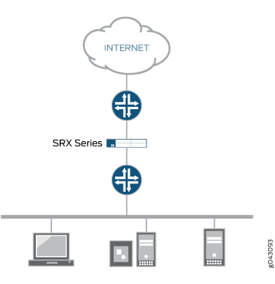
Traffic that arrives on a specific interface can be forwarded unchanged through another interface. This mapping of interfaces, called secure wire, allows an SRX Series to be deployed in the path of network traffic without requiring a change to routing tables or a reconfiguration of neighboring devices. Figure 1 shows a typical in-path deployment of an SRX Series with secure wire.
Secure wire maps two peer interfaces. It differs from transparent and route modes in that there is no switching or routing lookup to forward traffic. As long as the traffic is permitted by a security policy, a packet arriving on one peer interface is immediately forwarded unchanged out of the other peer interface. There is no routing or switching decision made on the packet. Return traffic is also forwarded unchanged.
Secure wire mapping is configured with the secure-wire
statement at the [edit security
forwarding-options] hierarchy level; two
Ethernet logical interfaces must be specified. The Ethernet
logical interfaces must be configured with family
ethernet-switching and each pair of
interfaces must belong to the VLAN(s). The interfaces must be
bound to security zones and a security policy configured to
permit traffic between the zones.
For
secure wire deployments in switching environments, configure the
following flags in the ethernet-switching CLI
to enhance Layer 2 forwarding flexibility while maintaining
security defaults:
: This setting allows all Layer 2 traffic that is not IP-based pass through the firewall without stopping it.bypass-non-ip-unicast
: This setting controls how the firewall handles BPDUs. It only floods BPDU messages inside the VLAN they belong to, not across the whole device.bpdu-vlan-flooding
ethernet-switching {
block-non-ip-all;
bpdu-vlan-flooding;
bypass-non-ip-unicast;
no-packet-flooding {
no-trace-route;
}
}This feature is available on Ethernet logical interfaces only; both IPv4 and IPv6 traffic are supported. You can configure interfaces for access or trunk mode. Secure wire supports chassis cluster redundant Ethernet interfaces. This feature does not support security features not supported in transparent mode, including NAT and IPsec VPN.
Secure wire supports Layer 7 features like AppSecure, SSL proxy, Content Security and IPS/IDP.
Secure wire is a special case of Layer 2 transparent mode on SRX Series Firewalls that provide point-to-point connections. This means that the two interfaces of a secure wire must ideally be directly connected to Layer 3 entities, such as routers or hosts. Secure wire interfaces can be connected to switches. However, note that a secure wire interface forwards all arriving traffic to the peer interface only if the traffic is permitted by a security policy.
Secure wire can coexist with Layer 3 mode. While you can configure Layer 2 and Layer 3 interfaces at the same time, traffic forwarding occurs independently on Layer 2 and Layer 3 interfaces.
Secure wire can coexist with Layer 2 transparent mode. If both features exist on the same SRX Series Firewall, you need to configure them in different VLANs.
Integrated routing and bridging (IRB) interfaces are not supported with secure wire.
See Also
Example: Simplifying SRX Series Firewall Deployment with Secure Wire over Access Mode Interfaces
If you are connecting an SRX Series Firewall to other network devices, you can use secure wire to simplify the device deployment in the network. No changes to routing or forwarding tables on the SRX Series Firewall and no reconfiguration of neighboring devices is needed. Secure wire allows traffic to be forwarded unchanged between specified access mode interfaces on an SRX Series Firewall as long as it is permitted by security policies or other security features. Follow this example if you are connecting an SRX Series Firewall to other network devices through access mode interfaces.
This example shows how to configure a secure wire mapping for two access mode interfaces. This configuration applies to scenarios where user traffic is not VLAN tagged.
Requirements
No special configuration beyond device initialization is required before configuring this feature.
Overview
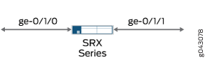
This example configures the secure wire access-sw that maps interface ge-0/0/3.0 to interface ge-0/0/4.0. The two peer interfaces are configured for access mode. The VLAN ID 10 is configured for the vlan-10 and the access mode interfaces.
A specific VLAN ID must be configured for a VLAN.
Topology
Figure 2 shows the access mode interfaces that are mapped in secure wire access-sw.

Configuration
Procedure
CLI Quick Configuration
Starting in Junos OS Release 15.1X49-D10 and Junos OS Release 17.3R1, some Layer 2 CLI configuration statements are enhanced, and some commands are changed. For detailed information about the modified hierarchies, see Enhanced Layer 2 CLI Configuration Statement and Command Changes for Security Devices.
The configuration statements shown below are for Junos OS Release 15.1X49-D10 or higher and Junos OS Release 17.3R1.
To quickly configure this example, copy the following commands, paste them into a text file, remove any line breaks, change any details necessary to match your network configuration, copy and paste the commands into the CLI at the [edit] hierarchy level, and then enter commit from configuration mode.
In switching mode, ethernet-switching interface must not be in security zone. You must enable transparent mode for ethernet-switching interfaces to be allowed in security zones by using the global-mode (Protocols) command.
set vlans vlan-10 vlan-id 10 set interfaces ge-0/0/3 unit 0 family ethernet-switching interface-mode access set interfaces ge-0/0/3 unit 0 family ethernet-switching vlan members 10 set interfaces ge-0/0/4 unit 0 family ethernet-switching interface-mode access set interfaces ge-0/0/4 unit 0 family ethernet-switching vlan members 10 set security forwarding-options secure-wire access-sw interface [ge-0/0/3.0 ge-0/0/4.0] set security zones security-zone trust interfaces ge-0/0/3.0 set security zones security-zone untrust interfaces ge-0/0/4.0 set security address-book book1 address mail-untrust 203.0.113.1 set security address-book book1 attach zone untrust set security address-book book2 address mail-trust 192.168.1.1 set security address-book book2 attach zone trust set security policies from-zone trust to-zone untrust policy permit-mail match source-address mail-trust set security policies from-zone trust to-zone untrust policy permit-mail match destination-address mail-untrust set security policies from-zone trust to-zone untrust policy permit-mail match application junos-mail set security policies from-zone trust to-zone untrust policy permit-mail then permit
Step-by-Step Procedure
The following example requires you to navigate various levels in the configuration hierarchy. For instructions on how to do that, see Using the CLI Editor in Configuration Mode in the CLI User Guide.
To configure a secure wire mapping for access mode interfaces:
Configure the VLAN.
[edit vlans vlan-10] user@host# set vlan-id 10
Configure the access mode interfaces.
[edit interfaces ] user@host# set ge-0/0/3 unit 0 family ethernet-switching interface-mode access user@host# set ge-0/0/4 unit 0 family ethernet-switching interface-mode access user@host# set ge-0/0/3 unit 0 family ethernet-switching vlan members 10 user@host# set ge-0/0/4 unit 0 family ethernet-switching vlan members 10
Configure the secure wire mapping.
[edit security forwarding-options] user@host# set secure-wire access-sw interface [ge-0/0/3.0 ge-0/0/4.0]
Configure security zones.
[edit security zones] user@host# set security-zone trust interfaces ge-0/0/3.0 user@host# set security-zone untrust interfaces ge-0/0/4.0
Create address book entries. Attach security zones to the address books.
[edit security address-book book1] user@host# set address mail-untrust 203.0.113.1 user@host# set attach zone untrust
[edit security address-book book1] user@host# set address mail-trust 192.168.1.1 user@host# set attach zone trust
Configure a security policy to permit mail traffic.
[edit security policies from-zone trust to-zone untrust] user@host# set policy permit-mail match source-address mail-trust user@host# set policy permit-mail match destination-address mail-untrust user@host# set policy permit-mail match application junos-mail user@host# set policy permit-mail then permit
Results
From configuration mode, confirm your configuration by entering the show vlans, show interfaces, show security forwarding-options, and show security zones commands. If the output does not display the intended configuration, repeat the instructions in this example to correct the configuration.
user@host# show vlans
vlan-10 {
vlan-id 10;
}
user@host# show interfaces
ge-0/0/3 {
unit 0 {
family ethernet-switching {
interface-mode access;
vlan {
members 10;
}
}
}
}
ge-0/0/4 {
unit 0 {
family ethernet-switching {
interface-mode access;
vlan {
members 10;
}
}
}
}
user@host# show security forwarding-options
secure-wire {
access-sw {
interface [ ge-0/0/3.0 ge-0/0/4.0 ];
}
}
user@host# show security zones
security-zone trust {
interfaces {
ge-0/0/3.0;
}
}
security-zone untrust {
interfaces {
ge-0/0/4.0;
}
}
user@host# show security policies
from-zone trust to-zone untrust {
policy permit-mail {
match {
source-address mail-trust;
destination-address mail-untrust;
application junos-mail;
}
then {
permit;
}
}
}
If you are done configuring the device, enter commit from configuration mode.
Verification
Confirm that the configuration is working properly.
Verifying Secure Wire Mapping
Purpose
Verify the secure wire mapping.
Action
From operational mode, enter the show security forwarding-options secure-wire command.
user@host> show security forward-options secure-wire Secure wire Interface Link Interface Link access-sw ge-0/0/3.0 down ge-0/0/4.0 down Total secure wires: 1
Verifying the VLAN
Purpose
Verify the VLAN.
Action
From operational mode, enter the show vlans vlan-10 command.
user@host> show vlans vlan-10
Routing instance VLAN name Tag Interfaces
default-switch vlan-10 10 ge-0/0/3.0
ge-0/0/4.0Verifying Policy Configuration
Purpose
Verify information about security policies..
Action
From operational mode, enter the show security policies detail command.
user@host> show security policies detail
Default policy: deny-all
Pre ID default policy: permit-all
Policy: permit-mail, action-type: permit, State: enabled, Index: 4, Scope Policy: 0
Policy Type: Configured
Sequence number: 1
From zone: trust, To zone: untrust
Source vrf group:
any
Destination vrf group:
any
Source addresses:
mail-trust(book2): 192.168.1.1/32
Destination addresses:
mail-untrust(book1): 203.0.113.1/32
Application: junos-mail
IP protocol: tcp, ALG: 0, Inactivity timeout: 1800
Source port range: [0-0]
Destination ports: 25
Per policy TCP Options: SYN check: No, SEQ check: No, Window scale: NoExample: Simplifying SRX Series Firewall Deployment with Secure Wire over Trunk Mode Interfaces
If you are connecting an SRX Series Firewall to other network devices, you can use secure wire to simplify the device deployment in the network. No changes to routing or forwarding tables on the SRX Series Firewall and no reconfiguration of neighboring devices is needed. Secure wire allows traffic to be forwarded unchanged between specified trunk mode interfaces on an SRX Series Firewall as long as it is permitted by security policies or other security features. Follow this example if you are connecting an SRX Series Firewall to other network devices through trunk mode interfaces.
Requirements
No special configuration beyond device initialization is required before configuring this feature.
Overview
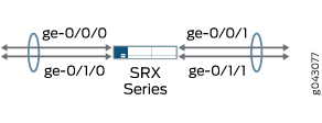
This example configures the secure wire trunk-sw that maps interface ge-0/1/0.0 to interface ge-0/1/1.0. The two peer interfaces are configured for trunk mode and carry user traffic tagged with VLAN IDs from 100 to 102. The VLAN ID list 100-102 is configured for the VLAN vlan-100 and the trunk mode interfaces.
A specific VLAN ID must be configured for a VLAN.
Topology
Figure 3 shows the trunk mode interfaces that are mapped in secure wire trunk-sw.
Configuration
Procedure
CLI Quick Configuration
To quickly configure this example, copy the
following commands, paste them into a text file, remove any line breaks,
change any details necessary to match your network configuration,
copy and paste the commands into the CLI at the [edit] hierarchy
level, and then enter commit from configuration mode.
set vlans vlan-100 vlan members 100-102 set interfaces ge-0/1/0 unit 0 family ethernet-switching interface-mode trunk vlan members 100-102 set interfaces ge-0/1/1 unit 0 family ethernet-switching interface-mode trunk vlan members 100-102 set security forwarding-options secure-wire trunk-sw interface [ge-0/1/0.0 ge-0/1/1.0] set security zones security-zone trust interfaces ge-0/1/0.0 set security zones security-zone untrust interfaces ge-0/1/1.0 set security policies default-policy permit-all
Step-by-Step Procedure
The following example requires you to navigate various levels in the configuration hierarchy. For instructions on how to do that, see Using the CLI Editor in Configuration Mode in the CLI User Guide.
To configure a secure wire mapping for trunk mode interfaces:
Configure the VLAN.
[edit vlans vlan-100] user@host# set vlan members 100-102
Configure the trunk mode interfaces.
[edit interfaces] user@host# set ge-0/1/0 unit 0 family ethernet-switching interface-mode trunk vlan members 100-102 user@host# set ge-0/1/1 unit 0 family ethernet-switching interface-mode trunk vlan members 100-102
Configure the secure wire mapping.
[edit security forwarding-options] user@host# set secure-wire trunk-sw interface [ge-0/1/0.0 ge-0/1/1.0]
Configure security zones.
[edit security zones] user@host# set security-zone trust interfaces ge-0/1/0.0 user@host# set security-zone untrust interfaces ge-0/1/1.0
Configure a security policy to permit traffic.
[edit security policies] user@host# set default-policy permit-all
Results
From configuration mode, confirm your configuration
by entering the show vlans, show interfaces, show security forwarding-options, and show security zones commands. If the output does not display the intended configuration,
repeat the instructions in this example to correct the configuration.
user@host# show vlans
vlan-100 {
vlan members 100-102;
}
user@host# show interfaces
ge-0/1/0 {
unit 0 {
family ethernet-switching {
interface-mode trunk;
vlan members 100-102;
}
}
}
ge-0/1/1 {
unit 0 {
family ethernet-switching {
interface-mode trunk;
vlan members 100-102;
}
}
}
user@host# show security forwarding-options
secure-wire trunk-sw {
interfaces [ge-0/1/0.0 ge-0/1/1.0];
}
user@host# show security zones
security-zone trust {
interfaces {
ge-0/1/0.0;
}
}
security-zone untrust {
interfaces {
ge-0/1/1.0;
}
}
If you are done configuring the device, enter commit from configuration mode.
Verification
Confirm that the configuration is working properly.
Verifying Secure Wire Mapping
Purpose
Verify the secure wire mapping.
Action
From operational mode, enter the show security
forwarding-options secure-wire command.
user@host> show security forward-options secure-wire Secure wire Interface Link Interface Link trunk-sw ge-0/1/0.0 up ge-0/1/1.0 up Total secure wires: 1
Verifying the VLAN
Purpose
Verify the VLAN.
Action
From operational mode, enter the show vlans command.
user@host> show vlans
Routing instance VLAN name VLAN ID Interfaces
default-switch vlan-100-vlan-0100 100 ge-0/1/0.0
ge-0/1/1.0
default-switch vlan-100-vlan-0101 101 ge-0/1/0.0
ge-0/1/1.0
default-switch vlan-100-vlan-0102 102 ge-0/1/0.0
ge-0/1/1.0VLANs are automatically expanded, with one VLAN for each VLAN ID in the VLAN ID list.
Example: Simplifying SRX Series Firewall Deployment with Secure Wire over Aggregated Interface Member Links
If you are connecting an SRX Series Firewall to other network devices, you can use secure wire to simplify the device deployment in the network. No changes to routing or forwarding tables on the SRX Series Firewall and no reconfiguration of neighboring devices is needed. Secure wire allows traffic to be forwarded unchanged between specified aggregated interface member links on an SRX Series Firewall as long as it is permitted by security policies or other security features. Follow this example if you are connecting an SRX Series Firewall to other network devices through aggregated interface member links.
While
LACP is not supported on individual secure wire interfaces, it is supported on
secure wire trunk interfaces when configured correctly. If you use LACP with VLAN
trunking over secure wire, you must set a native VLAN on the trunk interfaces. This
native VLAN must also be defined under the VLAN configuration and
included as a VLAN member on the trunk of all devices. This ensures LACP PDUs can be
sent and the LACP connection is established.
set vlans v100 vlan-id 100 set vlans v200 vlan-id 200 set interfaces ge-0/0/1 native-vlan-id 100 set interfaces ge-0/0/1 unit 0 family ethernet-switching interface-mode trunk set interfaces ge-0/0/1 unit 0 family ethernet-switching vlan members v100 set interfaces ge-0/0/1 unit 0 family ethernet-switching vlan members v200
On SRX210, SRX220, SRX240, SRX300, SRX320, SRX340, SRX345, SRX550, and SRX650 devices, when you create an aggregated interface with two or more ports and set the family to Ethernet switching, and if a link in the bundle goes down, the traffic forwarded through the same link will be rerouted two seconds later. This causes an outage for the traffic being sent to the link until reroute is complete.
Requirements
No special configuration beyond device initialization is required before configuring this feature.
Overview
This example configures secure wires for two aggregated Ethernet interface link bundles with two links each. Two separate secure wires ae-link1 and ae-link2 are configured using one link from each aggregated Ethernet link bundle. This static mapping requires that the two link bundles have the same number of links.
For link bundles, all logical interfaces of the secure wire mappings must belong to the same VLAN. VLAN ID 10 is configured for the VLAN vlan-10 and the logical interfaces. All logical interfaces of a link bundle must belong to the same security zone.
A specific VLAN ID or VLAN ID list must be configured for a VLAN.
Topology
Figure 4 shows the aggregated interfaces that are mapped in secure wire configurations.
Configuration
Procedure
CLI Quick Configuration
To quickly configure this example, copy the
following commands, paste them into a text file, remove any line breaks,
change any details necessary to match your network configuration,
copy and paste the commands into the CLI at the [edit] hierarchy
level, and then enter commit from configuration mode.
set vlans vlan-10 vlan-id 10 set interfaces ge-0/0/0 unit 0 family ethernet-switching interface-mode access vlan-id 10 set interfaces ge-0/0/1 unit 0 family ethernet-switching interface-mode access vlan-id 10 set interfaces ge-0/1/0 unit 0 family ethernet-switching interface-mode access vlan-id 10 set interfaces ge-0/1/1 unit 0 family ethernet-switching interface-mode access vlan-id 10 set security forwarding-options secure-wire ae-link1-sw interface [ge-0/1/0.0 ge-0/1/1.0] set security forwarding-options secure-wire ae-link2-sw interface [ge-0/0/0.0 ge-0/0/1.0] set security zones security-zone trust interfaces ge-0/0/0.0 set security zones security-zone trust interfaces ge-0/1/0.0 set security zones security-zone untrust interfaces ge-0/0/1.0 set security zones security-zone untrust interfaces ge-0/1/1.0 set security policies default-policy permit-all
Step-by-Step Procedure
The following example requires you to navigate various levels in the configuration hierarchy. For instructions on how to do that, see Using the CLI Editor in Configuration Mode in the CLI User Guide.
To configure a secure wire mapping for aggregated interface member links:
Configure the VLAN.
[edit vlans vlan-10] user@host# set vlan-id10
Configure the interfaces.
[edit interfaces ] user@host# set ge-0/0/0 unit 0 family ethernet-switching interface-mode access vlan-id 10 user@host# set ge-0/0/1 unit 0 family ethernet-switching interface-mode access vlan-id 10 user@host# set ge-0/1/0 unit 0 family ethernet-switching interface-mode access vlan-id 10 user@host# set ge-0/1/1 unit 0 family ethernet-switching interface-mode access vlan-id 10
Configure the secure wire mappings.
[edit security forwarding-options] user@host# set secure-wire ae-link1-sw interface [ ge-0/1/0.0 ge-0/1/1.0 ] user@host# set secure-wire ae-link2-sw interface [ ge-0/0/0.0 ge-0/0/1.0 ]
Configure security zones.
[edit security zones] user@host# set security-zone trust interfaces ge-0/0/0.0 user@host# set security-zone trust interfaces ge-0/1/0.0 user@host# set security-zone untrust interfaces ge-0/0/1.0 user@host# set security-zone untrust interfaces ge-0/1/1.0
Configure a security policy to permit traffic.
[edit security policies] user@host# set default-policy permit-all
Results
From configuration mode, confirm your configuration
by entering the show vlans, show interfaces, show security forwarding-options, and show security zones commands. If the output does not display the intended configuration,
repeat the instructions in this example to correct the configuration.
user@host# show vlans
vlan-10 {
vlan-id 10;
}
user@host# show interfaces
ge-0/0/0 {
unit 0 {
family ethernet-switching {
interface-mode access;
vlan-id 10;
}
}
}
ge-0/0/1 {
unit 0 {
family ethernet-switching {
interface-mode access;
vlan-id 10;
}
}
}
ge-0/1/0 {
unit 0 {
family ethernet-switching {
interface-mode access;
vlan-id 10;
}
}
}
ge-0/1/1{
unit 0 {
family ethernet-switching {
interface-mode access;
vlan-id 10;
}
}
}
user@host# show security forwarding-options
secure-wire ae-link1-sw {
interfaces [ge-0/1/0.0 ge-0/1/1.0];
}
secure-wire ae-link2-sw {
interfaces [ge-0/0/0.0 ge-0/0/1.0];
}
user@host# show security zones
security-zone trust {
interfaces {
ge-0/0/0.0;
ge-0/1/0.0;
}
}
security-zone untrust {
interfaces {
ge-0/0/1.0;
ge-0/1/1.0;
}
}
If you are done configuring the device, enter commit from configuration mode.
Verification
Confirm that the configuration is working properly.
Verifying Secure Wire Mapping
Purpose
Verify the secure wire mapping.
Action
From operational mode, enter the show security
forwarding-options secure-wire command.
user@host> show security forward-options secure-wire Secure wire Interface Link Interface Link ae-link1-sw ge-0/1/0.0 up ge-0/1/1.0 up ae-link2-sw ge-0/0/0.0 up ge-0/0/1.0 up Total secure wires: 2
Example: Simplifying Chassis Cluster Deployment with Secure Wire over Redundant Ethernet Interfaces
If you are connecting an SRX Series chassis cluster to other network devices, you can use secure wire to simplify the cluster deployment in the network. No changes to routing or forwarding tables on the cluster and no reconfiguration of neighboring devices is needed. Secure wire allows traffic to be forwarded unchanged between specified redundant Ethernet interfaces on the SRX Series chassis cluster as long as it is permitted by security policies or other security features. Follow this example if you are connecting an SRX Series chassis cluster to other network devices through redundant Ethernet interfaces.
Requirements
Before you begin:
Connect a pair of the same SRX Series Firewalls in a chassis cluster.
Configure the chassis cluster node ID and cluster ID.
Set the number of redundant Ethernet interfaces in the chassis cluster.
Configure the chassis cluster fabric.
Configure chassis cluster redundancy group (in this example redundancy group 1 is used).
For more information, see the Chassis Cluster User Guide for SRX Series Devices.
Overview
Secure wire is supported over redundant Ethernet interfaces in a chassis cluster. The two redundant Ethernet interfaces must be configured in the same redundancy group. If failover occurs, both redundant Ethernet interfaces must fail over together.
Secure wire mapping of redundant Ethernet link aggregation groups (LAGs) are not supported. LACP is not supported.
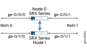
This example configures the secure wire reth-sw that maps ingress interface reth0.0 to egress interface reth1.0. Each redundant Ethernet interface consists of two child interfaces, one on each node of the chassis cluster. The two redundant Ethernet interfaces are configured for access mode. VLAN ID 10 is configured for the VLAN vlan-10 and the redundant Ethernet interfaces.
A specific VLAN ID or VLAN ID list must be configured for a VLAN.
Topology
Figure 5 shows the redundant Ethernet interfaces that are mapped in secure wire reth-sw.
Configuration
Procedure
CLI Quick Configuration
To quickly configure this example, copy the
following commands, paste them into a text file, remove any line breaks,
change any details necessary to match your network configuration,
copy and paste the commands into the CLI at the [edit] hierarchy
level, and then enter commit from configuration mode.
set vlans vlan-10 vlan-id 10 set interfaces ge-0/0/0 gigether-options redundant-parent reth0 set interfaces ge-0/0/1 gigether-options redundant-parent reth1 set interfaces ge-0/1/0 gigether-options redundant-parent reth0 set interfaces ge-0/1/1 gigether-options redundant-parent reth1 set interfaces reth0 unit 0 family ethernet-switching interface-mode access vlan-id 10 set interfaces reth1 unit 0 family ethernet-switching interface-mode access vlan-id 10 set interfaces reth0 redundant-ether-options redundancy-group 1 set interfaces reth1 redundant-ether-options redundancy-group 1 set security forwarding-options secure-wire reth-sw interface [reth0.0 reth1.0] set security zones security-zone trust interfaces reth0.0 set security zones security-zone untrust interfaces reth1.0 set security policies default-policy permit-all
Step-by-Step Procedure
The following example requires you to navigate various levels in the configuration hierarchy. For instructions on how to do that, see Using the CLI Editor in Configuration Mode in the CLI User Guide.
To configure a secure wire mapping for chassis cluster redundant Ethernet interfaces:
Configure the VLAN.
[edit vlans vlan-10]
user@host# set vlan-id 10
Configure the redundant Ethernet interfaces.
[edit interfaces ] user@host# set ge-0/0/0 gigether-options redundant-parent reth0 user@host# set ge-0/0/1 gigether-options redundant-parent reth1 user@host# set ge-0/1/0 gigether-options redundant-parent reth0 user@host# set ge-0/1/1 gigether-options redundant-parent reth1 user@host#set reth0 unit 0 family ethernet-switching interface-mode access vlan-id 10 user@host#set reth1 unit 0 family ethernet-switching interface-mode access vlan-id 10 user@host# set reth0 redundant-ether-options redundancy-group 1 user@host# set reth1 redundant-ether-options redundancy-group 1
Configure the secure wire mapping.
[edit security forwarding-options] user@host# set secure-wire reth-sw interface [reth0.0 reth1.0]
Configure security zones.
[edit security zones] user@host# set security-zone trust interfaces reth0.0 user@host# set security-zone untrust interfaces reth1.0
Configure a security policy to permit traffic.
[edit security policies]
user@host# set default-policy permit-all
Results
From configuration mode, confirm your configuration
by entering the show vlans, show interfaces, show security forwarding-options, and show security zones commands. If the output does not display the intended configuration,
repeat the instructions in this example to correct the configuration.
user@host# show vlans
vlan-10 {
vlan-id 10;
}
user@host# show interfaces
ge-0/0/0 {
gigether-options {
redundant-parent reth0;
}
}
ge-0/0/1 {
gigether-options {
redundant-parent reth1;
}
}
ge-0/1/0 {
gigether-options {
redundant-parent reth0;
}
}
ge-0/1/1 {
gigether-options {
redundant-parent reth1;
}
}
reth0 {
redundant-ether-options {
redundancy-group 1;
}
unit 0 {
family ethernet-switching {
interface-mode access;
vlan-id 10;
}
}
}
reth1 {
redundant-ether-options {
redundancy-group 1;
}
unit 0 {
family ethernet-switching {
interface-mode access;
vlan-id 10;
}
}
}
user@host# show security forwarding-options
secure-wire reth-sw {
interfaces [reth0.0 reth1.0];
}
user@host# show security zones
security-zone trust {
interfaces {
reth0.0;
}
}
security-zone untrust {
interfaces {
reth1.0;
}
}
If you are done configuring the device, enter commit from configuration mode.
Verification
Confirm that the configuration is working properly.
Verifying Secure Wire Mapping
Purpose
Verify the secure wire mapping.
Action
From operational mode, enter the show security
forwarding-options secure-wire command.
user@host> show security forward-options secure-wire node0: -------------------------------------------------------------------------- Secure wire Interface Link Interface Link reth-sw reth0.0 up reth1.0 up Total secure wires: 1 node1: -------------------------------------------------------------------------- Secure wire Interface Link Interface Link reth-sw reth0.0 up reth1.0 up Total secure wires: 1
Example: Simplifying Chassis Cluster Deployment with Secure Wire over Aggregated Redundant Ethernet Interfaces
If you are connecting an SRX Series chassis cluster to other network devices, you can use secure wire to simplify the cluster deployment in the network. No changes to routing or forwarding tables on the cluster and no reconfiguration of neighboring devices is needed. Secure wire allows traffic to be forwarded unchanged between specified redundant Ethernet interfaces on the SRX Series chassis cluster as long as it is permitted by security policies or other security features. Follow this example if you are connecting an SRX Series chassis cluster to other network devices through aggregated redundant Ethernet interfaces.
Secure wires cannot be configured for redundant Ethernet interface link aggregation groups (LAGs). For the secure wire mapping shown in this example, there is no LAG configuration on the SRX Series chassis cluster. Each redundant Ethernet interface consists of two child interfaces, one on each node of the chassis cluster. Users on upstream or downstream devices connected to the SRX Series cluster can configure the redundant Ethernet interface child links in LAGs.
Requirements
Before you begin:
Connect a pair of the same SRX Series Firewalls in a chassis cluster.
Configure the chassis cluster node ID and cluster ID.
Set the number of redundant Ethernet interfaces in the chassis cluster.
Configure the chassis cluster fabric.
Configure the chassis cluster redundancy group (in this example, redundancy group 1 is used).
For more information, see the Chassis Cluster User Guide for SRX Series Devices.
Overview
This example configures secure wires for four redundant Ethernet interfaces: reth0, reth1, reth2, and reth3. Each redundant Ethernet interface consists of two child interfaces, one on each node of the chassis cluster. All four redundant Ethernet interfaces must be in the same VLAN—in this example, the VLAN is vlan-0. Two of the redundant Ethernet interfaces, reth0.0 and reth2.0, are assigned to the trust zone, while the other two interfaces, reth1.0 and reth3.0, are assigned to the untrust zone.
This example configures the following secure wires:
reth-sw1 maps interface reth0.0 to interface reth1.0
reth-sw2 maps interface reth2.0 to reth3.0
All redundant Ethernet interfaces are configured for access mode. VLAN ID 10 is configured for the VLAN vlan-0 and the redundant Ethernet interfaces.
A specific VLAN ID or VLAN ID list must be configured for a VLAN.
Topology
Figure 6 shows the redundant Ethernet interface child links that are mapped in secure wire configurations reth-sw1 and reth-sw2. Each redundant Ethernet interface consists of two child interfaces, one on each node of the chassis cluster.
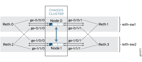
Users on upstream or downstream devices connected to the SRX Series cluster can configure redundant Ethernet interface child links in a LAG as long as the LAG does not span chassis cluster nodes. For example, ge-0/0/0 and ge-0/1/0 and ge-0/0/1 and ge-0/1/1 on node 0 can be configured as LAGs on connected devices. In the same way, ge-1/0/0 and ge-1/1/0 and ge-1/0/1 and ge-1/1/1 on node 1 can be configured as LAGs on connected devices.
Configuration
Procedure
CLI Quick Configuration
To quickly configure this example, copy the
following commands, paste them into a text file, remove any line breaks,
change any details necessary to match your network configuration,
copy and paste the commands into the CLI at the [edit] hierarchy
level, and then enter commit from configuration mode.
set vlans vlan-0 vlan-id 10 set interfaces ge-0/0/0 gigether-options redundant-parent reth0 set interfaces ge-0/0/1 gigether-options redundant-parent reth1 set interfaces ge-0/1/0 gigether-options redundant-parent reth2 set interfaces ge-0/1/1 gigether-options redundant-parent reth3 set interfaces ge-1/0/0 gigether-options redundant-parent reth0 set interfaces ge-1/0/1 gigether-options redundant-parent reth1 set interfaces ge-1/1/0 gigether-options redundant-parent reth2 set interfaces ge-1/1/1 gigether-options redundant-parent reth3 set interfaces reth0 unit 0 family ethernet-switching interface-mode access vlan-id 10 set interfaces reth1 unit 0 family ethernet-switching interface-mode access vlan-id 10 set interfaces reth2 unit 0 family ethernet-switching interface-mode access vlan-id 10 set interfaces reth3 unit 0 family ethernet-switching interface-mode access vlan-id 10 set interfaces reth0 redundant-ether-options redundancy-group 1 set interfaces reth1 redundant-ether-options redundancy-group 1 set interfaces reth2 redundant-ether-options redundancy-group 1 set interfaces reth3 redundant-ether-options redundancy-group 1 set security forwarding-options secure-wire reth-sw1 interface [reth0.0 reth1.0] set security forwarding-options secure-wire reth-sw2 interface [reth2.0 reth3.0] set security zones security-zone trust interfaces reth0.0 set security zones security-zone trust interfaces reth2.0 set security zones security-zone untrust interfaces reth1.0 set security zones security-zone untrust interfaces reth3.0 set security policies default-policy permit-all
Step-by-Step Procedure
The following example requires you to navigate various levels in the configuration hierarchy. For instructions on how to do that, see Using the CLI Editor in Configuration Mode in the CLI User Guide.
To configure a secure wire mapping for aggregated interface member links:
Configure the VLAN.
[edit vlans vlan-0] user@host# set vlan-id 10
Configure the redundant Ethernet interfaces.
[edit interfaces ] user@host# set ge-0/0/0 gigether-options redundant-parent reth0 user@host# set ge-0/0/1 gigether-options redundant-parent reth1 user@host# set ge-0/1/0 gigether-options redundant-parent reth2 user@host# set ge-0/1/1 gigether-options redundant-parent reth3 user@host# set ge-1/0/0 gigether-options redundant-parent reth0 user@host# set ge-1/0/1 gigether-options redundant-parent reth1 user@host# set ge-1/1/0 gigether-options redundant-parent reth2 user@host# set ge-1/1/1 gigether-options redundant-parent reth3 user@host# set reth0 unit 0 family ethernet-switching interface-mode access vlan-id 10 user@host# set reth1 unit 0 family ethernet-switching interface-mode access vlan-id 10 user@host# set reth2 unit 0 family ethernet-switching interface-mode access vlan-id 10 user@host# set reth3 unit 0 family ethernet-switching interface-mode access vlan-id 10 user@host# set reth0 redundant-ether-options redundancy-group 1 user@host# set reth1 redundant-ether-options redundancy-group 1 user@host# set reth2 redundant-ether-options redundancy-group 1 user@host# set reth3 redundant-ether-options redundancy-group 1
Configure the secure wire mappings.
[edit security forwarding-options] user@host# set secure-wire reth-sw1 interface [reth0.0 reth1.0] user@host# set secure-wire reth-sw2 interface [reth2.0 reth3.0]
Configure security zones.
[edit security zones] user@host# set security-zone trust interfaces reth0.0 user@host# set security-zone trust interfaces reth2.0 user@host# set security-zone untrust interfaces reth1.0 user@host# set security-zone untrust interfaces reth3.0
Configure a security policy to permit traffic.
[edit security policies]
user@host# set default-policy permit-all
Results
From configuration mode, confirm your configuration
by entering the show vlans, show interfaces, show security forwarding-options, and show security zones commands. If the output does not display the intended configuration,
repeat the instructions in this example to correct the configuration.
user@host# show vlans
    vlan-0 {
        vlan-id 10;
    }
    user@host# show interfaces
    ge-0/0/0 {
        gigether-options {
            redundant-parent reth0;
        }
    }
    ge-0/0/1 {
        gigether-options {
            redundant-parent reth1;
        }
    }
    ge-0/1/0 {
        gigether-options {
            redundant-parent reth2;
        }
    }
    ge-0/1/1 {
        gigether-options {
            redundant-parent reth3;
        }
    }
    ge-1/0/0 {
        gigether-options {
            redundant-parent reth0;
        }
    }
    ge-1/0/1 {
        gigether-options {
            redundant-parent reth1;
        }
    }
    ge-1/1/0 {
        gigether-options {
            redundant-parent reth2;
        }
    }
    ge-1/1/1 {
        gigether-options {
            redundant-parent reth3;
        }
    }
    reth0 {
        redundant-ether-options {
            redundancy-group 1;
        }
        unit 0 {
            family ethernet-switching {
                interface-mode access;
                vlan-id 10;
            }
        }
    }
    reth1 {
        redundant-ether-options {
            redundancy-group 1;
        }
        unit 0 {
            family ethernet-switching {
                interface-mode access;
                vlan-id 10;
            }
        }
    }
    reth2 {
        redundant-ether-options {
            redundancy-group 1;
        }
        unit 0 {
            family ethernet-switching {
                interface-mode access;
                vlan-id 10;
            }
        }
    }
    reth3 {
        redundant-ether-options {
            redundancy-group 1;
        }
        unit 0 {
            family ethernet-switching {
                interface-mode access;
                vlan-id 10;
            }
        }
    }
    user@host# show security forwarding-options
    secure-wire reth-sw1 {
        interfaces [reth0.0 reth1.0];
    }
    secure-wire reth-sw2 {
        interfaces [reth2.0 reth3.0];
    }
user@host# show security zones
    security-zone trust {
        interfaces {
            reth0.0;
            reth2.0;
        }
    }
    security-zone untrust {
        interfaces {
            reth1.0;
            reth3.0;
        }
    }
If you are done configuring the device, enter commit from configuration mode.
Verification
Confirm that the configuration is working properly.
Verifying Secure Wire Mapping
Purpose
Verify the secure wire mapping.
Action
From operational mode, enter the show security
forwarding-options secure-wire command.
user@host> show security forward-options secure-wire
node0:
--------------------------------------------------------------------------
Secure wire                       Interface       Link   Interface       Link
reth-sw1                          reth0.0         up     reth1.0         up
reth-sw2                          reth2.0         up     reth3.0         up

Total secure wires: 2

node1:
--------------------------------------------------------------------------
Secure wire                       Interface       Link   Interface       Link
reth-sw1                          reth0.0         up     reth1.0         up
reth-sw2                          reth2.0         up     reth3.0         up

Total secure wires: 2