Segment Routing LSP Configuration
Enabling Distributed CSPF for Segment Routing LSPs
With the distributed Constrained Shortest Path First (CSPF) for segment routing LSP feature, you can compute a segment routing LSP locally on the ingress device according to the constraints you have configured. With this feature, the LSPs are optimized based on the configured constraints and metric type (traffic-engineering or IGP). The LSPs are computed to utilize the available ECMP paths to the destination with segment routing label stack compression enabled or disabled.
Use Feature Explorer to confirm platform and release support for specific features.
Review the Platform-Specific Segment Routing LSP Behavior section for notes related to your platform.
- Distributed CSPF Computation Constraints
- Distributed CSPF Computation Algorithm
- Distributed CSPF Computation Database
- Configuring Distributed CSPF Computation Constraints
- Distributed CSPF Computation
- Anycast Computation
- Interaction Between Distributed CSPF Computation and SR-TE Features
- Distributed CSPF Computation Sample Configurations
Distributed CSPF Computation Constraints
Segment routing LSP paths are computed when all the configured constraints are met.
The distributed CSPF computation feature supports the following subset of constraints specified in the Internet draft, draft-ietf-spring-segment-routing-policy-03.txt, Segment Routing Policy for Traffic Engineering:
-
Inclusion and exclusion of administrative groups.
-
Inclusion of loose or strict hop IP addresses.
Note:You can specify only router IDs in the loose or strict hop constraints. Labels and other IP addresses cannot be specified as loose or strict hop constraints in Junos OS Release 19.2R1-S1.
-
Maximum number of segment IDs (SIDs) in the segment list.
-
Maximum number of segment lists per candidate segment routing path.
The distributed CSPF computation feature for segment routing LSPs does not support the following types of constraints and deployment scenarios:
-
Inter domain segment routing–traffic engineering (SR-TE) LSPs.
-
Unnumbered interfaces.
-
Multiple protocols routing protocols such as, OSPF, IS-IS, and BGP-LS, enabled at the same time.
-
Computation with prefixes or anycast addresses as destinations.
-
Including and excluding interface IP addresses as constraints.
Distributed CSPF Computation Algorithm
The distributed CSPF computation feature for segment routing LSPs uses the label stack compression algorithm with CSPF.
Label Stack Compression Enabled
A compressed label stack represents a set of paths from a source to a destination. It generally consists of node SIDs and adjacency SIDs. When label stack compression is enabled, the result of the computation is a set of paths that maximize ECMP to the destination, with minimum number of SIDs in the stack, while conforming to constraints.
Label Stack Compression Disabled
The multipath CSPF computation with label stack compression disabled finds up to N segment lists to destination, where:
-
The cost of all segment lists is equal to and the same as the shortest traffic-engineering metric to reach the destination.
-
Each segment list is comprised of adjacency SIDs.
-
The value of N is the maximum number of segment lists allowed for the candidate path by configuration.
-
No two segment lists are identical.
-
Each segment list satisfies all the configured constraints.
Distributed CSPF Computation Database
The database used for SR-TE computation has all links, nodes, prefixes and their
characteristics irrespective of whether traffic-engineering is enabled in those
advertising nodes. In other words, it is the union of the traffic-engineering
database (TED) and the IGP link state database of all domains that the computing
node has learnt from. As a result, for CSPF to work, you must include the
igp-topology statement at the [edit protocols isis
traffic-engineering] hierarchy level.
Configuring Distributed CSPF Computation Constraints
You can use a compute profile to logically group the computation constraints. These compute profiles are referenced by the segment routing paths for computing the primary and secondary segment routing LSPs.
To configure a compute profile, include the compute-profile statement at the [edit protocols
source-packet-routing] hierarchy level.
The configuration for the supported computation constraints include:
-
Administrative groups
You can configure admin-groups under the
[edit protocols mpls]hierarchy level. Junos OS applies the administrative group configuration to the segment routing traffic-engineering (SR-TE) interfaces.To configure the computation constraints you can specify three categories for a set of administrative groups. The computation constraint configuration can be common to all candidate segment routing paths, or it can be under individual candidate paths.
-
include-any—Specifies that any link with at least one of the configured administrative groups in the list is acceptable for the path to traverse. -
include-all—Specifies that any link with all of the configured administrative groups in the list is acceptable for the path to traverse. -
exclude—Specifies that any link which does not have any of the configured administrative groups in the list is acceptable for the path to traverse.
Note: Administrative groups are only advertised if you either:-
Enable RSVP on the interfaces.
-
Configure
edit protocols isis traffic-engineering advertisement alwaysif you dont want to enable RSVP.
-
-
Explicit path
You can specify a series of router IDs in the compute profile as a constraint for computing the SR-TE candidate paths. Each hop has to be an IPv4 address and can be of type strict or loose. If the type of a hop is not configured, strict is used. You must include the
computeoption under the segment-list statement when specifying the explicit path constraint. -
Maximum number of segment lists (ECMP paths)
You can associate a candidate path with a number of dynamic segment-lists. The paths are ECMP paths, where each segment-list translates into a next hop gateway with active weight. These paths are a result of path computation with or without compression.
You can configure this attribute using the
maximum-computed-segment-lists maximum-computed-segment-listsoption under the compute-profile configuration statement. This configuration determines the maximum number of such segment lists computed for a given primary and secondary LSP. -
Maximum segment list depth
The maximum segment list depth computation parameter ensures that amongst the ECMP paths that satisfy all other constraints such as administrative group, only the paths that have segment lists less than or equal to the maximum segment list depth are used. When you configure this parameter as a constraint under the compute-profile, it overrides the
maximum-segment-list-depthconfiguration under the[edit protocols source-packet-routing]hierarchy level, if present.You can configure this attribute using the
maximum-segment-list-depth maximum-segment-list-depthoption under the compute-profile configuration statement. -
Protected or unprotected adjacency SIDs
You can configure protected or unprotected adjacency SID as a constraint under the compute-profile to avoid links with the specified SID type.
Protected adjacency SIDs are configured to indicate that the adjacency SID has a backup path for protection. This configuration enables the network to support topology-independent loop-free alternate (TI-LFA) fast reroute for link or node failures.
Unprotected adjacency indicates there are no backup paths available, so link or node failure protection cannot be ensured. If both protected and unprotected SIDs exist on an IGP link and no
protectedorunprotectedconstraint is applied, the computation by default, uses the unprotected SID.Note: We support SR-TE local computation with OSPF as the underlay IGP forprotectedandunprotectedadjacency SIDs. -
Metric type
You can specify the type of metric on the link to be used for computation. By default, SR-TE LSPs use traffic-engineering metrics of the links for computation. The traffic-engineering metric for links is advertised by traffic-engineering extensions of IGP protocols. However, you may also choose to use the IGP-metric for computation by using the metric-type configuration in the compute profile.
You can configure this attribute using the
metric-type (igp | te)option under the compute-profile configuration statement.
Distributed CSPF Computation
The SR-TE candidate paths are computed locally such that they satisfy the configured constraints. When label stack compression is disabled, the multi-path CSPF computation result is a set of adjacency SID stacks. When label stack compression is enabled, the result is a set of compressed label stacks (composed of adjacent SIDs and node SIDs).
When secondary paths are computed, the links, nodes and SRLGs taken by the primary paths are not avoided for computation. For more information on primary and secondary paths, see Configuring Primary and Secondary LSPs.
For any LSPs with unsuccessful computation result, the computation is retried as traffic-engineering database (TED) changes.
Anycast Computation
You can configure anycast IP as an SR-TE endpoint and segment hop constraint. The computation must include an anycast SID in the result for compression scenarios, while for non-compression scenarios, it must include an adjacency SID to all egress nodes.
Interaction Between Distributed CSPF Computation and SR-TE Features
- Weights Associated With Paths of an SR-TE Policy
- BFD Liveliness Detection
- inherit-label-nexthops
- Auto-Translate Feature
Weights Associated With Paths of an SR-TE Policy
You can configure weights against computed and static SR-TE paths, which contribute to the next hops of the route. However, a single path that has computation enabled can result in multiple segment lists. These computed segment lists are treated as ECMP amongst themselves. You can assign hierarchical ECMP weights to these segments, considering the weights assigned to each of the configured primaries.
BFD Liveliness Detection
You can configure BFD liveliness detection for the computed primary or secondary paths. Every computed primary or secondary path can result in multiple segment lists, as a result, the BFD parameters configured against the segment lists are applied to all the computed segment lists. If all the active primary paths go down, the pre-programmed secondary path (if provided) becomes active.
inherit-label-nexthops
You are not required to explicitly enable the
inherit-label-nexthops configuration under the
[edit protocols source-packet-routing segment-list
segment-list-name] hierarchy for the computed
primary or secondary paths, as it is a default behavior.
Auto-Translate Feature
You can configure the auto-translate feature on the segment lists, and the primary or secondary paths with the auto-translate feature reference these segment lists. On the other hand, the primary or secondary on which compute feature is enabled cannot reference any segment list. As a result, you cannot enable both the compute feature and the auto-translate feature for a given primary or secondary path. However, you could have an LSP configured with a primary path with compute type and another with auto-translate type.
Distributed CSPF Computation Sample Configurations
Example 1
In Example 1,
-
The non-computed primary path references a configured segment-list. In this example, the configured segment list static_sl1 is referenced, and it also serves as the name for this primary path.
-
A computed primary should have a name configured, and this name should not reference any configured segment list. In this example, compute_segment1 is not a configured segment list.
-
The compute_profile_red compute-profile is applied to the primary path with the name compute_segment1.
-
The compute_profile_red compute-profile includes a segment list of type
compute, which is used to specify the explicit path constraint for the computation.
[edit protocols
                    source-packet-routing]
segment-list static_sl1{
hop1 label 80000
}
segment-list exp_path1 {
hop1 ip-address 10.1.1.1 loose
hop2 ip-address 10.2.2.2
compute
}
compute-profile compute_profile_red {
include-any red
segment-list exp_path1
maximum-segment-list-depth 5
}
The weights for computed path next-hops and static next-hops are 2 and 3, respectively. Assuming the next-hops for computed paths are comp_nh1, comp_nh2, and comp_nh3, and the next-hop for static path is static_nh, the weights are applied as follows:
|
Next-Hop |
Weight |
|---|---|
|
comp_nh1 |
2 |
|
comp_nh2 |
2 |
|
comp_nh3 |
2 |
|
static_nh |
9 |
Example 2
In Example 2, both the primary and secondary paths can be of compute type and can have their own compute-profiles.
[edit protocols source-packet-routing]
compute-profile compute_profile_green{
include-any green
maximum-segment-list-depth 5
}
compute-profile compute_profile_red{
include-any red
maximum-segment-list-depth 8
}
Example 3
In Example 3, when compute is mentioned under a primary or secondary path, it results in local computation of a path to the destination without any constraints or other parameters for the computation.
[edit protocols source-packet-routing]
source-routing-path srte_colored_policy1 {
to 10.5.5.5
color 5
binding-sid 10001
primary {
compute_segment1 {
compute
}
}
}
Static Segment Routing Label Switched Path
The segment routing architecture enables the ingress devices in a core network to steer traffic through explicit paths. You can configure these paths using segment lists to define the paths that the incoming traffic should take. The incoming traffic may be labeled or IP traffic, causing the forwarding operation at the ingress device to be either a label swap, or a destination-based lookup.
- Static Segment Routing LSP in MPLS Networks
- Example: Configuring Static Segment Routing Label Switched Path
Static Segment Routing LSP in MPLS Networks
Source packet routing or segment routing is a control-plane architecture that enables an ingress devices in a core network to steer traffic through a specific set of nodes and links in the network without relying on the intermediate nodes in the network to determine the actual path it should take. You can configure these paths using segment lists to define the paths that the incoming traffic should take. The incoming traffic may be labeled or IP traffic, causing the forwarding operation at the ingress device to be either a label swap, or a destination-based lookup.
- Introduction to Segment Routing LSPs
- Benefits of using Segment Routing LSPs
- Colored Static Segment Routing LSP
- Non-Colored Static Segment Routing LSP
- Static Segment Routing LSP Provisioning
- Static Segment Routing LSP Limitations
- Color-Based Mapping of VPN Services
- Tunnel Templates for PCE-Initiated Segment Routing LSPs
Introduction to Segment Routing LSPs
Segment routing leverages the source routing paradigm. A device steers a packet through an ordered list of instructions, called segments. A segment can represent any instruction, topological or service-based. A segment can have a local semantic to a segment routing node or to a global node within a segment routing domain. Segment routing enforces a flow through any topological path and service chain while maintaining per-flow state only at the ingress device to the segment routing domain. Segment routing can be directly applied to the MPLS architecture with no change on the forwarding plane. A segment is encoded as an MPLS label. An ordered list of segments is encoded as a stack of labels. The segment to process is on the top of the stack. Upon completion of a segment, the related label is popped from the stack.
Segment routing LSPs can either be dynamic or static in nature.
Dynamic segment routing LSPs—When a segment routing LSP is created either by an external controller and downloaded to an ingress device through Path Computation Element Protocol (PCEP) extensions, or from a BGP segment routing policy through BGP segment routing extensions, the LSP is dynamically provisioned. The segment list of the dynamic segment routing LSP is contained in the PCEP Explicit Route Object (ERO), or the BGP segment routing policy of the LSP. |
Static segment routing LSPs—When a segment routing LSP is created on the ingress device through local configuration, the LSP is statically provisioned. A static segment routing LSP can further be classified as colored and non-colored LSPs based on the configuration of the For example: [edit protocols]
source-packet-routing {
source-routing-path lsp_name {
to destination_address;
color color_value;
binding-sid binding-label;
primary segment_list_1_name weight weight;
...
primary segment_list_n_name weight weight;
secondary segment_list_n_name;
sr-preference sr_preference_value;
}
}
Here, each primary and secondary statement refers to a segment list. [edit protocols]
source-packet-routing {
segment-list segment_list_name {
hop_1_name label sid_label;
...
hop_n_name label sid_label;
}
}
|
Benefits of using Segment Routing LSPs
Static segment routing does not rely on per LSP forwarding state on transit routers. Hence, removing the need of provisioning and maintaining per LSP forwarding state in the core.
Provide higher scalability to MPLS networks.
Colored Static Segment Routing LSP
A static segment routing LSP configured with the color statement is called a colored LSP.
Understanding Colored Static Segment Routing LSPs
Similar to a BGP segment routing policy, the ingress route of the colored LSP is installed in the inetcolor.0 or inet6color.0 routing tables, with destination-ip-address, color as key for mapping IP traffic.
A static colored segment routing LSP may have a binding SID, for which a route is installed in the mpls.0 routing table. This binding SID label is used to map labeled traffic to the segment routing LSP. The gateways of the route are derived from the segment list configurations under the primary and secondary paths.
Segment List of Colored Segment Routing LSPs
The colored static segment routing LSPs already provide support for first hop label mode of resolving an LSP. However, first hop IP mode is not supported for colored segment routing LSPs. A commit check feature is introduced to ensure that all the segment lists contributing to the colored routes have the minimum label present for all hops. If this requirement is not met, the commit is blocked.
Non-Colored Static Segment Routing LSP
A static segment routing LSP that is configured without the color statement is a non-colored LSP. Similar to PCEP segment routing tunnels, the ingress route is installed in the inet.3 or inet6.3 routing tables.
Junos OS supports non-colored static segment routing LSPs on ingress routers. You can provision non-colored static segment routing LSP by configuring one source routed path and one or more segment lists. These segment lists can be used by multiple non-colored segment routing LSPs.
Understanding Non-Colored Segment Routing LSPs
The non-colored segment routing LSP has a unique name and a destination IP address. An ingress route to the destination is installed in the inet.3 routing table with a default preference of 8 and a metric of 1. This route allows non-colored services to be mapped to the segment routing LSP pertaining to the destination. In case the non-colored segment routing LSP does not require an ingress route then the ingress route can be disabled. A non-colored segment routing LSP uses binding SID label to achieve segment routing LSP stitching. This label that can be used to model the segment routing LSP as a segment that may be further used to construct other segment routing LSPs in a hierarchical manner. The transit of the binding SID label, by default, has a preference of 8 and a metric of 1.
Statically configured non-colored segment routing LSPs on the ingress device are reported to the Path Computation Element (PCE) through a Path Computation Element Protocol (PCEP) session. These non-colored segment routing LSPs may have binding service identifier (SID) labels associated with them. With this feature, the PCE can use this binding SID label in the label stack to provision PCE-initiated segment routing LSP paths.
A non-colored segment routing LSP can have a maximum of 8 primary paths. If there are multiple operational primary paths then the packet forwarding engine (PFE) distributes traffic over the paths based on the load balancing factors like the weight configured on the path. This is equal cost multi path (ECMP) if none of the paths have a weight configured on them or weighted ECMP if at least one of the paths has a non-zero weight configured on the paths. In both the cases, when one or some of the paths fail, the PFE rebalances the traffic over the remaining paths that automatically leads to achieving path protection. A non-colored segment routing LSP can have a secondary path for dedicated path protection. Upon failure of a primary path, the PFE rebalances the traffic to the remaining functional primary paths. Otherwise, the PFE switches the traffic to the backup path, hence achieving path protection. A non-colored segment routing LSP may specify a metric at [edit protocols source-packet-routing source-routing-path lsp-name] for its ingress and binding-SID routes. Multiple non-colored segment routing LSPs have the same destination address that contribute to the next hop of the ingress route.
Multiple non-colored segment routing LSPs have the same destination address that contribute to the next hop of the ingress route. Each path ,either primary or secondary, of each segment routing LSP is considered as a gateway candidate, if the path is functional and the segment routing LSP has the best preference of all these segment routing LSPs. However, the maximum number of gateways that the next-hop can hold cannot exceed the RPD multi-path limit, which is 128 by default. Extra paths are pruned, firstly secondary paths and then primary paths. A given segment list may be referred multiple times as primary or secondary paths by these segment routing LSPs. In this case, there are multiple gateways, each having a unique segment routing LSP tunnel ID. These gateways are distinct, although they have identical outgoing label stack and interface. A non-colored segment routing LSP and a colored segment routing LSP may also have the same destination address. However, they correspond to different destination addresses for ingress routes, as the colored segment routing LSP’s destination address is constructed with both its destination address and color.
In the case where a static non-colored segment routing LSP and a PCEP-created segment routing LSP co-exist and have the same to address that contributes to the same ingress route, if they also have the same preference. Otherwise, the segment routing LSP with the best preference is installed for the route.
Segment List of Non-Colored Segment Routing LSPs
A segment list consists of a list of hops. These hops are based on the SID label or an IP address. The number of SID labels in the segment list should not exceed the maximum segment list limit. Maximum segment-list binding to a LSP tunnel is increased from 8 to 128, with maximum 1000 tunnels per system. A maximum of 128 primary paths are supported per static segment routing LSP. You can configure the maximum segment list limit at the [edit protocols source-packet-routing] hierarchy level.
The first hop of the non-colored static LSPs provides support for SID labels, in addition to IP addresses. With the first hop label support, MPLS fast reroute (FRR) and weighted equal-cost multipath is enabled for resolving the static non-colored segment routing LSPs, similar to colored static LSPs.
For the first-hop label mode to take effect, you must include the inherit-label-nexthops statement globally or individually for a segment list, and the first hop of the segment list must include both IP address and label. If the first hop includes only IP address, the inherit-label-nexthops statement does not have any effect.
You can configure inherit-label-nexthops at any one of the following hierarchies. The inherit-label-nexthops statement takes effect only if the segment list first hop includes both IP address and label.
Segment list level—At the
[edit protocols source-packet-routing segment-list
                        segment-list-name]
hierarchy level.Globally—At the
[edit protocols source-packet-routing]hierarchy level.
When the inherit-label-nexthops statement is configured globally, it takes precedence over the segment-list level configuration, and the inherit-label-nexthops configuration is applied to all the segment lists. When the inherit-label-nexthops statement is not configured globally, only segment lists with both labels and IP address present in the first hop, and configured with inherit-label-nexthops statement are resolved using SID labels.
For dynamic non-colored static LSPs, that is the PCEP-driven segment routing LSPs, the inherit-label-nexthops statement must be enabled globally, as the segment-level configuration is not applied.
Table 1 describes the mode of segment routing LSP resolution based on the first hop specification.
First Hop Specification |
Mode of LSP Resolution |
|---|---|
IP address only For example: segment-list path-1 {
hop-1 ip-address 172.16.12.2;
hop-2 label 1000012;
hop-3 label 1000013;
hop-4 label 1000014;
}
|
The segment list is resolved using the IP address. |
SID only For example: segment-list path-2 {
hop-1 label 1000011;
hop-2 label 1000012;
hop-3 label 1000013;
hop-4 label 1000014;
}
|
The segment list is resolved using SID labels. |
IP address and SID (without the For example: segment-list path-3 {
hop1 {
label 801006;
ip-address 172.16.1.2;
}
hop-2 label 1000012;
hop-3 label 1000013;
hop-4 label 1000014;
}
|
By default, the segment list is resolved using IP address. |
IP address and SID (with the For example: segment-list path-3 {
inherit-label-nexthops;
hop1 {
label 801006;
ip-address 172.16.1.2;
}
hop-2 label 1000012;
hop-3 label 1000013;
hop-4 label 1000014;
}
|
The segment list is resolved using SID labels. |
You can use the show route ip-address protocol spring-te active-path table inet.3 command to view the non-colored segment routing traffic-engineered LSPs having multiple segment lists installed in the inet.3 routing table.
For example:
user@host> show route 10.7.7.7 protocol spring-te active-path table inet.3
inet.3: 42 destinations, 59 routes (41 active, 0 holddown, 1 hidden)
+ = Active Route, - = Last Active, * = Both
10.7.7.7/32 *[SPRING-TE/8] 00:01:25, metric 1, metric2 0
> to 10.11.1.2 via et-0/0/0.1, Push 801007
to 10.21.1.2 via et-0/0/2.1, Push 801007
to 10.102.1.2 via et-0/0/0.2, Push 801007, Push 801002(top)
to 10.21.1.2 via et-0/0/2.2, Push 801007, Push 801005(top)
to 10.103.1.2 via et-0/0/0.3, Push 801007, Push 801003(top)
to 10.203.1.2 via et-0/0/2.3, Push 801007, Push 801006(top)
to 10.104.1.2 via et-0/0/0.4, Push 801007, Push 801003, Push 801002(top)
to 10.204.1.2 via et-0/0/2.4, Push 801007, Push 801006, Push 801005(top)
The first hop type of segment lists of a static segment routing LSP can cause a commit to fail, if:
Different segment lists of a tunnel have different first hop resolution types. This is applicable to both colored and non-colored static segment routing LSPs. However, this does not apply for PCEP-driven LSPs; a system log message is generated for the mismatch in the first hop resolution type at the time of computing the path.
For example:
segment-list path-1 { hop-1 ip-address 172.16.12.2; hop-2 label 1000012; hop-3 label 1000013; hop-4 label 1000014; } segment-list path-2 { hop-1 label 1000011; hop-2 label 1000012; hop-3 label 1000013; hop-4 label 1000014; } source-routing-path lsp1 { to 172.16.10.1; primary { path-1; path-2; } }The commit of tunnel lsp1 fails, as path-1 is of IP address mode and path-2 is of label mode.
The binding SID is enabled for the static non-colored LSP whose segment list type is SID label.
For example:
segment-list path-3 {
    hop-1 label 1000011;
    hop-2 label 1000012;
    hop-3 label 1000013;
    hop-4 label 1000014;
}
source-routing-path lsp1 {
    to 172.16.10.1;
    binding-sid 333;
    primary {
        path-3;
    }
}
Static Segment Routing LSP Provisioning
Segment provisioning is performed on per-router basis. For a given segment on a router, a unique service identifier (SID) label is allocated from a desired label pool which may be from the dynamic label pool for an adjacency SID label or from the segment routing global block (SRGB) for a prefix SID or node SID. The adjacency SID label can be dynamically allocated, which is the default behavior, or be allocated from a local static label pool (SRLB). A route for the SID label is then installed in the mpls.0 table.
Junos OS allows static segment routing LSPs by configuring the segment statement at the [edit protocols mpls static-label-switched-path static-label-switched-path] hierarchy level. A static segment LSP is identified by a unique SID label that falls under Junos OS static label pool. You can configure the Junos OS static label pool by configuring the static-label-range static-label-range statement at the [edit protocols mpls label-range] hierarchy level.
Static Segment Routing LSP Limitations
Junos OS currently has a limitation that the next hop cannot be built to push more than the maximum segment list depth labels. So, a segment list with more than the maximum SID labels (excluding the SID label of the first hop which is used to resolve forwarding next-hop) is not usable for colored or non-colored segment routing LSPs. Also, the actual number allowed for a given segment routing LSP may be even lower than the maximum limit, if an MPLS service is on the segment routing LSP or the segment routing LSP is on a link or a node protection path. In all cases, the total number of service labels, SID labels, and link or node protection labels must not exceed the maximum segment list depth. You can configure the maximum segment list limit at
[edit protocols source-packet-routing]hierarchy level. Multiple non-colored segment routing LSPs with less than or equal to the maximum SID labels can be stitched together to construct a longer segment routing LSP. This is called segment routing LSP stitching. It can be achieved using binding-SID label.The segment routing LSP stitching is actually performed at path level. If a non-colored segment routing LSP has multiple paths that is multiple segment lists, each path can be independently stitched to another non-colored segment routing LSP at a stitching point. A non-colored segment routing LSP which is dedicated to stitching may disable ingress route installation by configuring
no-ingressstatement at[edit protocols source-packet-routing source-routing-path lsp-name]hierarchy level.A maximum of 128 primary paths and 1 secondary path are supported per non-colored static segment routing LSP. If there is a violation in configuration, commit check fails with an error.
Maximum segment-list binding to a LSP tunnel is increased from 8 to 128, with maximum 1000 tunnels per system. A maximum of 128 primary paths are supported per static segment routing LSP. As a limitation, the maximum sensor support for LSP path is 32000 only.
If any segment-list is configured with more labels than the maximum segment list depth, the configuration commit check fails with an error.
Color-Based Mapping of VPN Services
You can specify color as a protocol next hop constraint (in addition to the IPv4 or IPv6 address) for resolving transport tunnels over static colored and BGP segment routing traffic-engineered (SR-TE) LSPs. This is called the color-IP protocol next hop resolution, where you are required to configure a resolution-map and apply to the VPN services. With this feature, you can enable color-based traffic steering of Layer 2 and Layer 3 VPN services.
Junos OS supports colored SR-TE LSPs associated with a single color. The color-based mapping of VPN services feature is supported on static colored LSPs and BGP SR-TE LSPs.
- VPN Service Coloring
- Specifying VPN Service Mapping Mode
- Color-IP Protocol Next Hop Resolution
- Fallback to IP Protocol Next Hop Resolution
- BGP Labeled Unicast Color-based Mapping over SR-TE
- Supported and Unsupported Features for Color-Based Mapping of VPN Services
VPN Service Coloring
In general, a VPN service may be assigned a color on the egress router where the VPN NLRI is advertised, or on an ingress router where the VPN NLRI is received and processed.
You can assign a color to the VPN services at different levels:
Per routing instance.
Per BGP group.
Per BGP neighbor.
Per prefix.
Once you assign a color, the color is attached to a VPN service in the form of BGP color extended community.
You can assign multiple colors to a VPN service, referred to as multi-color VPN services. In such cases, the last color attached is considered as the color of the VPN service, and all other colors are ignored.
Multiple colors are assigned by egress and/or ingress devices through multiple policies in the following order:
BGP export policy on the egress device.
BGP import policy on the ingress device.
VRF import policy on the ingress device.
The two modes of VPN service coloring are:
Egress Color Assignment
In this mode, the egress device (that is, the advertiser of the VPN NLRI) is responsible for coloring the VPN service. To enable this mode, you can define a routing policy, and apply it in the VPN service’s routing-instance vrf-export, group export, or group neighbor export at the [edit protocols bgp] hierarchy level. The VPN NLRI is advertised by BGP with the specified color extended community.
For example:
[edit policy-options]
community red-comm {
    members color:0:50;
}
[edit policy-options]
policy-statement pol-color {
    term t1 {
        from {
            [any match conditions];
        }
        then {
            community add red-comm;
            accept;
        }
    }
}
[edit routing-instances]
vpn-X {
    ...
    vrf-export pol-color ...;
}
Or
When you apply the routing policy as an export policy of a BGP group or BGP neighbor, you must include the vpn-apply-export statement at the BGP, BGP group, or BGP neighbor level in order for the policy to take an effect on the VPN NLRI.
[edit protocols bgp]
group PEs {
    ...
    neighbor PE-A {
        export pol-color ...;
        vpn-apply-export;
    }
}
The routing policies are applied to Layer 3 VPN prefix NLRIs, Layer 2 VPN NRLIs, and EVPN NLRIs. The color extended community is inherited by all the VPN routes, imported, and installed in the target VRFs on one or multiple ingress devices.
Ingress Color Assignment
In this mode, the ingress device (that is, the receiver of the VPN NLRI) is responsible for coloring the VPN service. To enable this mode, you can define a routing policy, and apply it to the VPN service’s routing-instance vrf-import, group import, or group neighbor import at the [edit protocols bgp] hierarchy level. All the VPN routes matching the routing policy is attached with the specified color extended community.
For example:
[edit policy-options]
community red-comm {
    members color:0:50;
}
[edit policy-options]
policy-statement pol-color {
    term t1 {
        from {
            [any match conditions];
        }
        then {
            community add red-comm;
            accept;
        }
    }
}
[edit routing-instances]
vpn-Y {
    ...
    vrf-import pol-color ...;
}
Or
[edit protocols bgp]
group PEs {
    ...
    neighbor PE-B {
        import pol-color ...;
    }
}
Specifying VPN Service Mapping Mode
To specify flexible VPN service mapping modes, you must define a policy using the resolution-map statement, and refer the policy in a VPN service’s routing-instance vrf-import, group import, or group neighbor import at the [edit protocols bgp] hierarchy level. All the VPN routes matching the routing policy are attached with the specified resolution-map.
For example:
[edit policy-options]
resolution-map map-A {
    <mode-1>;
    <mode-2>;
    ...
}
policy-statement pol-resolution {
    term t1 {
        from {
            [any match conditions];
        }
        then {
            resolution-map map-A;
            accept;
        }
    }
}
You can apply import policy to the VPN service’s routing-instance.
[edit routing-instances]
vpn-Y {
    ...
    vrf-import pol-resolution ...;
}
You can also apply the import policy to a BGP group or BGP neighbor.
[edit protocols bgp]
group PEs {
    ...
    neighbor PE-B {
        import pol-resolution ...;
    }
}
Each VPN service mapping mode should have a unique name defined in the resolution-map. Only a single entry of IP-color is supported in the resolution-map, where the VPN route(s) are resolved using a colored-IP protocol next hop in the form of ip-address:color.
Color-IP Protocol Next Hop Resolution
The protocol next hop resolution process is enhanced to support colored-IP protocol next hop resolution. For a colored VPN service, the protocol next hop resolution process takes a color and a resolution-map, builds a colored-IP protocol next hop in the form of IP-address:color, and resolves the protocol next hop in the inet6color.0 routing table.
You must configure a policy to support multipath resolution of colored Layer 2 VPN, Layer 3 VPN, or EVPN services over colored LSPs. The policy must then be applied with the relevant RIB table as the resolver import policy.
For example:
[edit policy-options]
policy-statement mpath {
    then multipath-resolve;
}
[edit routing-options]
resolution {
    rib bgp.l3vpn.0 {
        inetcolor-import mpath;
    }
}

resolution {
    rib bgp.l3vpn-inet6.0 {
        inet6color-import mpath;
    }
}

resolution {
    rib bgp.l2vpn.0 {
        inetcolor-import mpath;
    }
}

resolution {
    rib mpls.0 {
        inetcolor-import mpath;
    }
}

resolution {
    rib bgp.evpn.0 {
        inetcolor-import mpath;
    }
}
Fallback to IP Protocol Next Hop Resolution
If a colored VPN service does not have a resolution-map applied to it, the VPN service ignores its color and falls back to the IP protocol next hop resolution. Conversely, if a non-colored VPN service has a resolution-map applied to it, the resolution-map is ignored, and the VPN service uses the IP protocol next hop resolution.
The fallback is a simple process from colored SR-TE LSPs to LDP LSPs, by using a RIB group for LDP to install routes in inet{6}color.0 routing tables. A longest prefix match for a colored-IP protocol next hop ensures that if a colored SR-TE LSP route does not exist, an LDP route with a matching IP address should be returned.
BGP Labeled Unicast Color-based Mapping over SR-TE
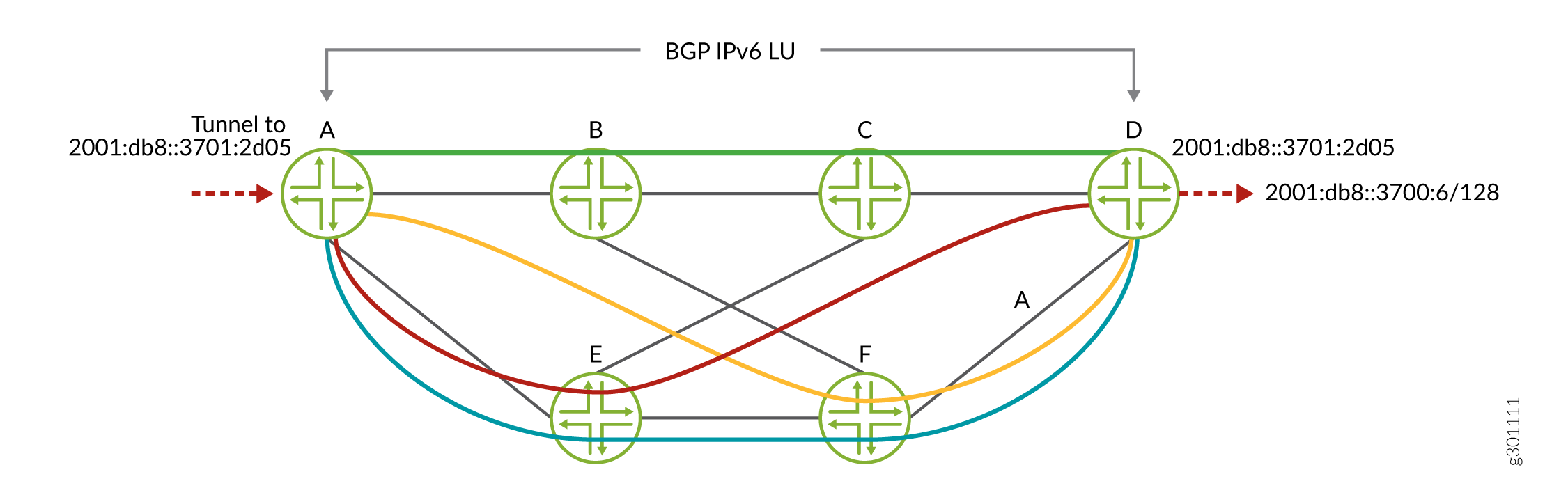
BGP Labeled Unicast (BGP-LU) can resolve IPv4 or IPv6 routes over segment routing–traffic engineering (SR-TE) for both IPv4 and IPv6 address families. BGP-LU supports mapping a BGP community color and defining a resolution map for SR-TE. A colored protocol next hop is constructed and it is resolved on a colored SR-TE tunnel in the inetcolor.0 or inet6color.0 table. BGP uses inet.3 and inet6.3 tables for non-color based mapping. This enables you to advertise BGP-LU IPv6 and IPv4 prefixes with an IPv6 next-hop address in IPv6-only networks where routers do not have any IPv4 addresses configured. With this feature, Currently we support BGP IPv6 LU over SR-TE with IS-IS underlay.
In Figure 1, the controller configures 4 colored tunnels in an IPv6 core network configured with SR-TE. Each colored tunnel takes a different path to the destination router D depending on the defined resolution map. The controller configures a colored SR-TE tunnel to 2001:db8::3701:2d05 interface in router D . BGP imports policies to assign a color and resolution map to the received prefix 2001:db8::3700:6/128. Based on the assigned community color, BGP-LU resolves the colored next hop for BGP IPv6 LU prefix according to the assigned resolution map policy.
BGP-LU supports the following scenarios:
BGP IPv4 LU over colored BGP IPv4 SR-TE, with IS-IS/OSPF IPv4 SR extensions.
BGP IPv4 LU over static colored and non-colored IPv4 SR-TE, with IS-IS/OSPF IPv4 SR extensions.
BGP IPv6 LU over colored BGP IPv6 SR-TE, with IS-IS IPv6 SR extensions.
BGP IPv6 LU over static colored and non-colored IPv6 SR-TE, with IS-IS IPv6 SR extensions.
IPv6 Layer 3 VPN services with IPv6 local address and IPv6 neighbor address.
IPv6 Layer 3 VPN services over BGP IPv6 SR-TE, with IS-IS IPv6 SR extensions.
IPv6 Layer 3 VPN services over static-colored and non-colored IPv6 SR-TE, with IS-IS IPv6 SR extensions.
Supported and Unsupported Features for Color-Based Mapping of VPN Services
The following features and functionality are supported with color-based mapping of VPN services:
BGP Layer 2 VPN (Kompella Layer 2 VPN)
BGP EVPN
Resolution-map with a single IP-color option.
Colored IPv4 and IPv6 protocol next hop resolution.
Routing information base (also known as routing table) group based fallback to LDP LSP in inetcolor.0 routing table.
Colored SR-TE LSP.
Virtual platforms.
64-bit Junos OS.
Logical systems.
BGP labeled unicast.
The following features and functionality are not supported with color-based mapping of VPN services:
Colored MPLS LSPs, such as RSVP, LDP, BGP-LU, static.
Layer 2 circuit
FEC-129 BGP auto-discovered and LDP-signaled Layer 2 VPN.
VPLS
MVPN
IPv4 and IPv6 using resolution-map.
Tunnel Templates for PCE-Initiated Segment Routing LSPs
You can configure a tunnel template for PCE-initiated segment routing LSPs to pass down two additional parameters for these LSPs - Bidirectional forwarding detection (BFD) and LDP tunneling.
When a PCE-Initiated segment routing LSP is being created, the LSP is checked against policy statements (if any) and if there is a match, the policy applies the configured template for that LSP. The template configuration is inherited only if it is not provided by the LSP source (PCEP); for example, metric.
To configure a template:
Include the source-routing-path-template statement at the
[edit protocols
                    source-packet-routing]
hierarchy level. You can configure the additional BFD and LDP tunneling parameters here.Include the source-routing-path-template-map statement at the
[edit protocols source-packet-routing]hierarchy level to list the policy statements against which the PCE-initiated LSP should be checked.Define a policy to list the LSPs on which the template should be applied.
The
fromstatement can include either the LSP name or LSP regular expression using thelspandlsp-regexmatch conditions. These options are mutually exclusive, so you can specify only one option at a given point in time.The
thenstatement must include thesr-te-templateoption with an accept action. This applies the template to the PCE-initiated LSP.
Take the following into consideration when configuring a template for PCE-initiated LSPs:
Template configuration is not applicable to staticalyy configured segment routing LSPs, or any other client’s segment routing LSP.
PCEP-provided configuration has precedence over template configuration.
PCEP LSP does not inherit template segment-list configuration.
Example: Configuring Static Segment Routing Label Switched Path
This example shows how to configure static segment routing label switched paths (LSPs) in MPLS networks. This configuration helps to bring higher scalability to MPLS networks.
Requirements
This example uses the following hardware and software components:
-
Seven MX Series 5G Universal Routing Platforms
-
Junos OS Release 18.1 or later running on all the routers
Before you begin, be sure you configure the device interfaces.
Overview
Junos OS a set of explicit segment routing paths are configured on the ingress router
of a non-colored static segment routing tunnel by configuring the
segment-list
statement at the [edit protocols source-packet-routing] hierarchy
level. You can configure segment routing tunnel by configuring the
source-routing-path statement at [edit protocols
source-packet-routing] hierarchy level. The segment routing tunnel has
a destination address and one or more primary paths and optionally secondary paths
that refer to the segment list. Each segment list consists of a sequence of hops.
For non-colored static segment routing tunnel, the first hop of the segment list
specifies an immediate next hop IP address and the second to Nth hop specifies the
segment identifies (SID) labels corresponding to the link or node which the path
traverses. The route to the destination of the segment routing tunnel is installed
in inet.3 table.
Topology
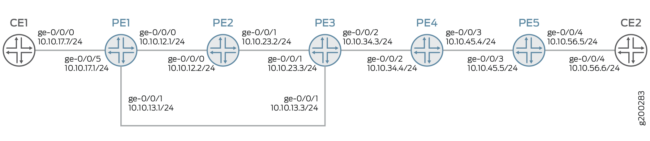
In this example, configure layer 3 VPN on the provider edge routers PE1 and PE5. Configure the MPLS protocol on all the routers. The segment routing tunnel is configured from router PE1 to router PE5 with a primary path configured on router PE1 and router PE5 . Router PE1 is also configured with secondary path for path protection. The transit routers PE2 to PE4 are configured with adjacency SID labels with label pop and an outgoing interface.
Configuration
CLI Quick Configuration
To quickly configure this example, copy the following commands, paste them into a
text file, remove any line breaks, change any details necessary to match your
network configuration, copy and paste the commands into the CLI at the
[edit] hierarchy level, and then enter
commit from configuration mode.
PE1
set interfaces ge-0/0/0 unit 0 family inet address 10.10.12.1/24
set interfaces ge-0/0/0 unit 0 family mpls maximum-labels 5
set interfaces ge-0/0/1 unit 0 family inet address 10.10.13.1/24
set interfaces ge-0/0/1 unit 0 family mpls maximum-labels 5
set interfaces ge-0/0/5 unit 0 family inet address 10.10.17.1/24
set routing-options autonomous-system 65000
set routing-options forwarding-table export load-balance-policy
set routing-options forwarding-table chained-composite-next-hop ingress l3vpn
set protocols mpls interface ge-0/0/0.0
set protocols mpls interface ge-0/0/1.0
set protocols mpls label-range static-label-range 1000000 1000999
set protocols bgp group pe type internal
set protocols bgp group pe local-address 192.168.147.211
set protocols bgp group pe family inet-vpn unicast
set protocols bgp group pe neighbor 192.168.146.181
set protocols ospf area 0.0.0.0 interface ge-0/0/0.0
set protocols ospf area 0.0.0.0 interface lo0.0
set protocols ospf area 0.0.0.0 interface ge-0/0/1.0
set protocols source-packet-routing segment-list sl-15-primary hop-1 ip-address 10.10.13.3
set protocols source-packet-routing segment-list sl-15-primary hop-2 label 1000134
set protocols source-packet-routing segment-list sl-15-primary hop-3 label 1000145
set protocols source-packet-routing segment-list sl-15-backup hop-1 ip-address 10.10.12.2
set protocols source-packet-routing segment-list sl-15-backup hop-2 label 1000123
set protocols source-packet-routing segment-list sl-15-backup hop-3 label 1000134
set protocols source-packet-routing segment-list sl-15-backup hop-4 label 1000145
set protocols source-packet-routing source-routing-path lsp-15 to 192.168.146.181
set protocols source-packet-routing source-routing-path lsp-15 binding-sid 1000999
set protocols source-packet-routing source-routing-path lsp-15 primary sl-15-primary
set protocols source-packet-routing source-routing-path lsp-15 secondary sl-15-backup
set policy-options policy-statement VPN-A-export term a from protocol ospf
set policy-options policy-statement VPN-A-export term a from protocol direct
set policy-options policy-statement VPN-A-export term a then community add VPN-A
set policy-options policy-statement VPN-A-export term a then accept
set policy-options policy-statement VPN-A-export term b then reject
set policy-options policy-statement VPN-A-import term a from protocol bgp
set policy-options policy-statement VPN-A-import term a from community VPN-A
set policy-options policy-statement VPN-A-import term a then accept
set policy-options policy-statement VPN-A-import term b then reject
set policy-options policy-statement bgp-to-ospf from protocol bgp
set policy-options policy-statement bgp-to-ospf from route-filter 10.10.0.0/16 orlonger
set policy-options policy-statement bgp-to-ospf then accept
set policy-options policy-statement load-balance-policy then load-balance per-packet
set policy-options community VPN-A members target:65000:1
set routing-instances VRF1 instance-type vrf
set routing-instances VRF1 interface ge-0/0/5.0
set routing-instances VRF1 route-distinguisher 192.168.147.211:1
set routing-instances VRF1 vrf-import VPN-A-import
set routing-instances VRF1 vrf-export VPN-A-export
set routing-instances VRF1 vrf-table-label
set routing-instances VRF1 protocols ospf export bgp-to-ospf
set routing-instances VRF1 protocols ospf area 0.0.0.0 interface ge-0/0/5.0
PE2
set interfaces ge-0/0/0 unit 0 family inet address 10.10.12.2/24
set interfaces ge-0/0/0 unit 0 family mpls
set interfaces ge-0/0/1 unit 0 family inet address 10.10.23.2/24
set interfaces ge-0/0/1 unit 0 family mpls
set protocols mpls static-label-switched-path adj-23 segment 1000123
set protocols mpls static-label-switched-path adj-23 segment next-hop 10.10.23.3
set protocols mpls static-label-switched-path adj-23 segment pop
set protocols mpls static-label-switched-path adj-21 segment 1000221
set protocols mpls static-label-switched-path adj-21 segment next-hop 10.10.12.1
set protocols mpls static-label-switched-path adj-21 segment pop
set protocols mpls interface ge-0/0/0.0
set protocols mpls interface ge-0/0/1.0
set protocols mpls label-range static-label-range 1000000 1000999
set protocols ospf area 0.0.0.0 interface ge-0/0/0.0
set protocols ospf area 0.0.0.0 interface ge-0/0/1.0
PE3
set interfaces ge-0/0/0 unit 0 family inet address 10.10.13.3/24
set interfaces ge-0/0/0 unit 0 family mpls
set interfaces ge-0/0/1 unit 0 family inet address 10.10.23.3/24
set interfaces ge-0/0/1 unit 0 family mpls
set interfaces ge-0/0/2 unit 0 family inet address 10.10.34.3/24
set interfaces ge-0/0/2 unit 0 family mpls
set protocols mpls static-label-switched-path adj-34 segment 1000134
set protocols mpls static-label-switched-path adj-34 segment next-hop 10.10.34.4
set protocols mpls static-label-switched-path adj-34 segment pop
set protocols mpls static-label-switched-path adj-32 segment 1000232
set protocols mpls static-label-switched-path adj-32 segment next-hop 10.10.23.2
set protocols mpls static-label-switched-path adj-32 segment pop
set protocols mpls interface ge-0/0/1.0
set protocols mpls interface ge-0/0/2.0
set protocols mpls label-range static-label-range 1000000 1000999
set protocols ospf area 0.0.0.0 interface ge-0/0/1.0
set protocols ospf area 0.0.0.0 interface ge-0/0/2.0
set protocols ospf area 0.0.0.0 interface ge-0/0/0.0
PE4
set interfaces ge-0/0/2 unit 0 family inet address 10.10.34.4/24
set interfaces ge-0/0/2 unit 0 family mpls
set interfaces ge-0/0/3 unit 0 family inet address 10.10.45.4/24
set interfaces ge-0/0/3 unit 0 family mpls
set protocols mpls static-label-switched-path adj-45 segment 1000145
set protocols mpls static-label-switched-path adj-45 segment next-hop 10.10.45.5
set protocols mpls static-label-switched-path adj-45 segment pop
set protocols mpls static-label-switched-path adj-43 segment 1000243
set protocols mpls static-label-switched-path adj-43 segment next-hop 10.10.34.3
set protocols mpls static-label-switched-path adj-43 segment pop
set protocols mpls interface ge-0/0/2.0
set protocols mpls interface ge-0/0/3.0
set protocols mpls label-range static-label-range 1000000 1000999
set protocols ospf area 0.0.0.0 interface ge-0/0/2.0
set protocols ospf area 0.0.0.0 interface ge-0/0/3.0
PE5
set interfaces ge-0/0/3 unit 0 family inet address 10.10.45.5/24
set interfaces ge-0/0/3 unit 0 family mpls maximum-labels 5
set interfaces ge-0/0/4 unit 0 family inet address 10.10.56.5/24
set routing-options autonomous-system 65000
set protocols mpls interface ge-0/0/3.0
set protocols mpls label-range static-label-range 1000000 1000999
set protocols bgp group pe type internal
set protocols bgp group pe local-address 192.168.146.181
set protocols bgp group pe family inet-vpn unicast
set protocols bgp group pe neighbor 192.168.147.211
set protocols ospf area 0.0.0.0 interface ge-0/0/3.0
set protocols ospf area 0.0.0.0 interface lo0.0
set protocols bfd sbfd local-discriminator 0.0.0.32 minimum-receive-interval 1000
set protocols source-packet-routing segment-list sl-51 hop-1 ip-address 10.10.45.4
set protocols source-packet-routing segment-list sl-51 hop-2 label 1000243
set protocols source-packet-routing segment-list sl-51 hop-3 label 1000232
set protocols source-packet-routing segment-list sl-51 hop-4 label 1000221
set protocols source-packet-routing source-routing-path lsp-51 to 192.168.147.211
set protocols source-packet-routing source-routing-path lsp-51 primary sl-51
set policy-options policy-statement VPN-A-export term a from protocol ospf
set policy-options policy-statement VPN-A-export term a from protocol direct
set policy-options policy-statement VPN-A-export term a then community add VPN-A
set policy-options policy-statement VPN-A-export term a then accept
set policy-options policy-statement VPN-A-export term b then reject
set policy-options policy-statement VPN-A-import term a from protocol bgp
set policy-options policy-statement VPN-A-import term a from community VPN-A
set policy-options policy-statement VPN-A-import term a then accept
set policy-options policy-statement VPN-A-import term b then reject
set policy-options policy-statement bgp-to-ospf from protocol bgp
set policy-options policy-statement bgp-to-ospf from route-filter 10.10.0.0/16 orlonger
set policy-options policy-statement bgp-to-ospf then accept
set policy-options community VPN-A members target:65000:1
set routing-instances VRF1 instance-type vrf
set routing-instances VRF1 interface ge-0/0/4.0
set routing-instances VRF1 route-distinguisher 192.168.146.181:1
set routing-instances VRF1 vrf-import VPN-A-import
set routing-instances VRF1 vrf-export VPN-A-export
set routing-instances VRF1 vrf-table-label
set routing-instances VRF1 protocols ospf export bgp-to-ospf
set routing-instances VRF1 protocols ospf area 0.0.0.0 interface ge-0/0/4.0
CE1
set interfaces ge-0/0/0 unit 0 family inet address 10.10.17.7/24
set protocols ospf area 0.0.0.0 interface ge-0/0/0.0
CE2
set interfaces ge-0/0/4 unit 0 family inet address 10.10.56.6/24
set protocols ospf area 0.0.0.0 interface ge-0/0/4.0
Configuring Device PE1
Step-by-Step Procedure
The following example requires that you navigate various levels in the configuration hierarchy. For information about navigating the CLI, see Using the CLI Editor in Configuration Mode in the CLI User Guide.
To configure Device PE1:
-
Configure the interfaces.
[edit interfaces]
set ge-0/0/0 unit 0 family inet address 10.10.12.1/24
set ge-0/0/0 unit 0 family mpls maximum-labels 5
set ge-0/0/1 unit 0 family inet address 10.10.13.1/24
set ge-0/0/1 unit 0 family mpls maximum-labels 5
set ge-0/0/5 unit 0 family inet address 10.10.17.1/24
-
Configure autonomous system number and options to control packet forwarding routing options.
[edit routing-options]
set autonomous-system 65000
set forwarding-table export load-balance-policy
set forwarding-table chained-composite-next-hop ingress l3vpn
-
Configure the interfaces with the MPLS protocol and configure the MPLS label range.
[edit protocols mpls]
set interface ge-0/0/0.0
set interface ge-0/0/1.0
set label-range static-label-range 1000000 1000999
-
Configure the type of peer group, local address, protocol family for NLRIs in updates, and IP address of a neighbor for the peer group.
[edit protocols bgp]
set group pe type internal
set group pe local-address 192.168.147.211
set group pe family inet-vpn unicast
set group pe neighbor 192.168.146.181
-
Configure the protocol area interfaces.
[edit protocols ospf]
set area 0.0.0.0 interface ge-0/0/0.0
set area 0.0.0.0 interface lo0.0
set area 0.0.0.0 interface ge-0/0/1.0
-
Configure the IPv4 address and labels of primary and secondary paths for source routing-traffic engineering (TE) policies of protocol source packet routing (SPRING).
[edit protocols source-packet-routing segment-list]
set sl-15-primary hop-1 ip-address 10.10.13.3
set sl-15-primary hop-2 label 1000134
set sl-15-primary hop-3 label 1000145
set sl-15-backup hop-1 ip-address 10.10.12.2
set sl-15-backup hop-2 label 1000123
set sl-15-backup hop-3 label 1000134
set sl-15-backup hop-4 label 1000145
-
Configure destination IPv4 address, binding SID label, primary, and secondary source routing path for protocol SPRING.
[edit protocols source-packet-routing source-routing-path]
set lsp-15 to 192.168.146.181
set lsp-15 binding-sid 1000999
set lsp-15 primary sl-15-primary
set lsp-15 secondary sl-15-backup
-
Configure policy options.
[edit policy-options policy-statement]
set VPN-A-export term a from protocol ospf
set VPN-A-export term a from protocol direct
set VPN-A-export term a then community add VPN-A
set VPN-A-export term a then accept
set VPN-A-export term b then reject
set VPN-A-import term a from protocol bgp
set VPN-A-import term a from community VPN-A
set VPN-A-import term a then accept
set VPN-A-import term b then reject
set bgp-to-ospf from protocol bgp
set bgp-to-ospf from route-filter 10.10.0.0/16 orlonger
set bgp-to-ospf then accept
set load-balance-policy then load-balance per-packet
-
Configure BGP community information.
[edit policy-options]
set community VPN-A members target:65000:1
-
Configure routing instance VRF1 with instance type, interface, router distinguisher, VRF import, export and table label. Configure export policy and interface of area for protocol OSPF.
[edit routing-instances VRF1]
set instance-type vrf
set interface ge-0/0/5.0
set route-distinguisher 192.168.147.211:1
set vrf-import VPN-A-import
set vrf-export VPN-A-export
set vrf-table-label
set protocols ospf export bgp-to-ospf
set protocols ospf area 0.0.0.0 interface ge-0/0/5.0
Results
From configuration mode, confirm your configuration by entering the show interfaces, show policy-options, show protocols, show routing-options, and show routing-instances commands. If the output does not display the intended configuration, repeat the instructions in this example to correct the configuration.
[edit]
user@PE1# show
   interfaces {
    ge-0/0/0 {
        unit 0 {
            family inet {
                address 10.10.12.1/24;
            }
            family mpls {
                maximum-labels 5;
            }
        }
    }
    ge-0/0/1 {
        unit 0 {
            family inet {
                address 10.10.13.1/24;
            }
            family mpls {
                maximum-labels 5;
            }
        }
    }
    ge-0/0/5 {
        unit 0 {
            family inet {
                address 10.10.17.1/24;
            }
        }
    }
}
policy-options {
    policy-statement VPN-A-export {
        term a {
            from protocol [ ospf direct ];
            then {
                community add VPN-A;
                accept;
            }
        }
        term b {
            then reject;
        }
    }
    policy-statement VPN-A-import {
        term a {
            from {
                protocol bgp;
                community VPN-A;
            }
            then accept;
        }
        term b {
            then reject;
        }
    }
    policy-statement bgp-to-ospf {
        from {
            protocol bgp;
            route-filter 10.10.0.0/16 orlonger;
        }
        then accept;
    }
    policy-statement load-balance-policy {
        then {
            load-balance per-packet;
        }
    }
    community VPN-A members target:65000:1;
}
routing-instances {
    VRF1 {
        instance-type vrf;
        protocols {
            ospf {
                area 0.0.0.0 {
                    interface ge-0/0/5.0;
                }
                export bgp-to-ospf;
            }
        }
        interface ge-0/0/5.0;
        route-distinguisher 192.168.147.211:1;
        vrf-import VPN-A-import;
        vrf-export VPN-A-export;
        vrf-table-label;
    }
}
routing-options {
    autonomous-system 65000;
    forwarding-table {
        export load-balance-policy;
        chained-composite-next-hop {
            ingress {
                l3vpn;
            }
        }
    }
}
protocols {
    bgp {
        group pe {
            type internal;
            local-address 192.168.147.211;
            family inet-vpn {
                unicast;
            }
            neighbor 192.168.146.181;
        }
    }
    mpls {
        label-range {
            static-label-range 1000000 1000999;
        }
        interface ge-0/0/0.0;
        interface ge-0/0/1.0;
    }
    ospf {
        area 0.0.0.0 {
            interface ge-0/0/0.0;
            interface lo0.0;
            interface ge-0/0/1.0;
        }
    }
    source-packet-routing {
        segment-list sl-15-primary {
            hop-1 ip-address 10.10.13.3;
            hop-2 label 1000134;
            hop-3 label 1000145;
        }
        segment-list sl-15-backup {
            hop-1 ip-address 10.10.12.2;
            hop-2 label 1000123;
            hop-3 label 1000134;
            hop-4 label 1000145;
        }
        source-routing-path lsp-15 {
            to 192.168.146.181;
            binding-sid 1000999;
            primary {
                sl-15-primary;
            }
            secondary {
                sl-15-backup;
            }
        }
    }
}
Configuring Device PE2
Step-by-Step Procedure
The following example requires that you navigate various levels in the configuration hierarchy. For information about navigating the CLI, see Using the CLI Editor in Configuration Mode in the CLI User Guide.
-
Configure the interfaces.
[edit interfaces]
set ge-0/0/0 unit 0 family inet address 10.10.12.2/24
set ge-0/0/0 unit 0 family mpls
set ge-0/0/1 unit 0 family inet address 10.10.23.2/24
set ge-0/0/1 unit 0 family mpls
-
Configure the static LSP for protocol MPLS.
[edit protocols mpls static-label-switched-path]
set adj-23 segment 1000123
set adj-23 segment next-hop 10.10.23.3
set adj-23 segment pop
set adj-21 segment 1000221
set adj-21 segment next-hop 10.10.12.1
set adj-21 segment pop
-
Configure interfaces and static label range for protocol MPLS.
[edit protocols mpls]
set interface ge-0/0/0.0
set interface ge-0/0/1.0
set label-range static-label-range 1000000 1000999
-
Configure interfaces for protocol OSPF.
[edit protocols ospf area 0.0.0.0]
set interface ge-0/0/0.0
set interface ge-0/0/1.0
Results
From configuration mode on router PE2, confirm your configuration by entering the show interfaces and show protocols commands. If the output does not display the intended configuration, repeat the instructions in this example to correct the configuration.
[edit]
user@PE2# show
interfaces {
    ge-0/0/0 {
        unit 0 {
            family inet {
                address 10.10.12.2/24;
            }
            family mpls;
        }
    }
    ge-0/0/1 {
        unit 0 {
            family inet {
                address 10.10.23.2/24;
            }
            family mpls;
        }
    }
}
protocols {
    mpls {
        label-range {
            static-label-range 1000000 1000999;
        }
        interface ge-0/0/0.0;
        interface ge-0/0/1.0;
        static-label-switched-path adj-23 {
            segment {
                1000123;
                next-hop 10.10.23.3;
                pop;
            }
        }
        static-label-switched-path adj-21 {
            segment {
                1000221;
                next-hop 10.10.12.1;
                pop;
            }
        }
    }
    ospf {
        area 0.0.0.0 {
            interface ge-0/0/0.0;
            interface ge-0/0/1.0;
        }
    }
}
Verification
Confirm that the configuration is working properly.
- Verifying Route Entry of Routing Table inet.3 of Router PE1
- Verifying Route Table Entries of Routing Table mpls.0 of Router PE1
- Verifying SPRING Traffic Engineered LSP of Router PE1
- Verifying SPRING Traffic Engineered LSPs on the Ingress Router of Router PE1
- Verifying the Routing Table Entries of Routing Table mpls.0 of Router PE2
- Verifying the Status of Static MPLS LSP Segments of Router PE2
Verifying Route Entry of Routing Table inet.3 of Router PE1
Purpose
Verify the route entry of routing table inet.3 of router PE1.
Action
From operational mode, enter the show route table inet.3
command.
user@PE1> show route table inet.3
inet.3: 1 destinations, 1 routes (1 active, 0 holddown, 0 hidden)
+ = Active Route, - = Last Active, * = Both

192.168.146.181/32   *[SPRING-TE/8] 03:09:26, metric 1
                    > to 10.10.13.3 via ge-0/0/1.0, Push 1000145, Push 1000134(top)
                      to 10.10.12.2 via ge-0/0/0.0, Push 1000145, Push 1000134, Push 1000123(top)
Meaning
The output displays the ingress routes of segment routing tunnels.
Verifying Route Table Entries of Routing Table mpls.0 of Router PE1
Purpose
Verify the route entries of routing table mpls.0
Action
From operational mode, enter the show route table mpls.0
command.
user@PE1> show route table mpls.0
mpls.0: 6 destinations, 6 routes (6 active, 0 holddown, 0 hidden)
+ = Active Route, - = Last Active, * = Both

0                  *[MPLS/0] 03:25:52, metric 1
                      Receive
1                  *[MPLS/0] 03:25:52, metric 1
                      Receive
2                  *[MPLS/0] 03:25:52, metric 1
                      Receive
13                 *[MPLS/0] 03:25:52, metric 1
                      Receive
16                 *[VPN/0] 03:25:52
                    > via lsi.0 (VRF1), Pop
1000999            *[SPRING-TE/8] 03:04:03, metric 1
                    > to 10.10.13.3 via ge-0/0/1.0, Swap 1000145, Push 1000134(top)
                      to 10.10.12.2 via ge-0/0/0.0, Swap 1000145, Push 1000134, Push 1000123(top)
Meaning
The output displays the SID labels of segment routing tunnels.
Verifying SPRING Traffic Engineered LSP of Router PE1
Purpose
Verify SPRING traffic engineered LSPs on the ingress routers.
Action
From operational mode, enter the show spring-traffic-engineering
overview command.
user@PE1> show spring-traffic-engineering overview
Overview of SPRING-TE:
  Route preference: 8
  Number of LSPs: 1 (Up: 1, Down: 0)
  External controllers:
			< Not configured >
Meaning
The output displays the overview of SPRING traffic engineered LSPs on the ingress router.
Verifying SPRING Traffic Engineered LSPs on the Ingress Router of Router PE1
Purpose
Verify SPRING traffic engineered LSPs on the ingress router.
Action
From operational mode, enter the show spring-traffic-engineering lsp
detail command.
user@PE1# show spring-traffic-engineering lsp detail
Name: lsp-15
To: 192.168.146.181
State: Up
  Path: sl-15-primary
  Outgoing interface: ge-0/0/1.0
  BFD status: N/A (Up: 0, Down: 0)
  SR-ERO hop count: 3
    Hop 1 (Strict):
      NAI: IPv4 Adjacency ID, 0.0.0.0 -> 10.10.13.3
      SID type: None
    Hop 2 (Strict):
      NAI: None
      SID type: 20-bit label, Value: 1000134
    Hop 3 (Strict):
      NAI: None
      SID type: 20-bit label, Value: 1000145
  Path: sl-15-backup
  Outgoing interface: ge-0/0/0.0
  BFD status: N/A (Up: 0, Down: 0)
  SR-ERO hop count: 4
    Hop 1 (Strict):
      NAI: IPv4 Adjacency ID, 0.0.0.0 -> 10.10.12.2
      SID type: None
    Hop 2 (Strict):
      NAI: None
      SID type: 20-bit label, Value: 1000123
    Hop 3 (Strict):
      NAI: None
      SID type: 20-bit label, Value: 1000134
    Hop 4 (Strict):
      NAI: None
      SID type: 20-bit label, Value: 1000145


Total displayed LSPs: 1 (Up: 1, Down: 0)
Meaning
The output displays details of SPRING traffic engineered LSPs on the ingress router
Verifying the Routing Table Entries of Routing Table mpls.0 of Router PE2
Purpose
Verify the routing table entries of routing table mpls.0 of router PE2.
Action
From operational mode, enter the show route table mpls.0
command.
user@PE2> show route table mpls.0
mpls.0: 8 destinations, 8 routes (8 active, 0 holddown, 0 hidden)
+ = Active Route, - = Last Active, * = Both

0                  *[MPLS/0] 03:22:29, metric 1
                      Receive
1                  *[MPLS/0] 03:22:29, metric 1
                      Receive
2                  *[MPLS/0] 03:22:29, metric 1
                      Receive
13                 *[MPLS/0] 03:22:29, metric 1
                      Receive
1000123            *[MPLS/6] 03:22:29, metric 1
                    > to 10.10.23.3 via ge-0/0/1.0, Pop
1000123(S=0)       *[MPLS/6] 03:22:29, metric 1
                    > to 10.10.23.3 via ge-0/0/1.0, Pop
1000221            *[MPLS/6] 03:22:29, metric 1
                    > to 10.10.12.1 via ge-0/0/0.0, Pop
1000221(S=0)       *[MPLS/6] 03:22:29, metric 1
                    > to 10.10.12.1 via ge-0/0/0.0, Pop
Verifying the Status of Static MPLS LSP Segments of Router PE2
Purpose
Verify the status of MPLS LSP segments of router PE2.
Action
From operational mode, enter the show mpls static-lsp
command.
user@PE2> show mpls static-lsp
Ingress LSPs:
Total 0, displayed 0, Up 0, Down 0

Transit LSPs:
Total 0, displayed 0, Up 0, Down 0

Bypass LSPs:
Total 0, displayed 0, Up 0, Down 0

Segment LSPs:
LSPname                             SID-label       State
adj-21                              1000221         Up
adj-23                              1000123         Up
Total 2, displayed 2, Up 2, Down 0
Meaning
The output displays the status of static MPLS LSP segments of router PE2.
Routing Engine-based S-BFD for Segment-Routing Traffic Engineering with First-Hop Label Resolution
You can run seamless Bidirectional Forwarding Detection (S-BFD) over non-colored and colored label-switched paths (LSPs) with first-hop label resolution, using S-BFD as a fast mechanism to detect path failures.
- Understanding RE-based S-BFD for Segment-Routing Traffic Engineering with First-Hop Label Resolution
- S-BFD for SRv6 TE Paths
- Configuring RE-based S-BFD for Segment-Routing Traffic Engineering with First-Hop Label Resolution
- Auto Derivation of Remote Discriminator (RD) for S-BFD Session
- Example: Configuring Seamless Bidirectional Forwarding Detection (S-BFD) for SR-TE
Understanding RE-based S-BFD for Segment-Routing Traffic Engineering with First-Hop Label Resolution
S-BFD Static Segment-Routing Tunnels for First-Hop Labels
Segment-routing architecture enables ingress nodes in a core network to steer traffic through explicit paths through the network. The segment-routing traffic engineering (TE) next hop is a list or lists of segment identifiers (SIDs). These segment lists represent paths in the network that you want incoming traffic to take. The incoming traffic may be labeled or IP traffic and the forwarding operation at the ingress node may be a label swap or a destination-based lookup to steer the traffic onto these segment-routing TE paths in the forwarding path.
You can run seamless BFD (S-BFD) over non-colored and colored static segment-routing LSPs with first-hop label resolution and use S-BFD as a fast mechanism to detect path failures and to trigger global convergence. S-BFD requires fewer state changes than BFD requires, thus speeding up the reporting of path failures.
Given a segment-routing tunnel with one or multiple primary LSPs and optionally a secondary LSP, you can enable S-BFD on any of those LSPs. If an S-BFD session goes down, the software updates the segment-routing tunnel’s route by deleting the next hops of the failed LSPs. If the first-hop label of the LSP points to more than one immediate next hop, the kernel continues to send S-BFD packets if at least one next hop is available (underlying next-hop reachability failure detection must be faster than the duration of the S-BFD detection timer).
This model is supported for auto-translate-derived LSPs.
LSP-level S-BFD
An S-BFD session is created for each unique label-stack+address-family combination. You can configure identical segment lists and enable S-BFD for all of them. The segment lists that have identical label-stack+address-family combinations share the same S-BFD session. The source address for the S-BFD session is set to the least configured loopback address (except the special addresses) under the main instance.
Ensure that the chosen source address is routable.
The address family of an LSP is derived based on the address family of the “to” address in the segment-routing TE tunnel. The state of the LSP with S-BFD configured also depends on whether BFD is up—if S-BFD is configured for an LSP, the LSP route isn’t calculated until S-BFD reports the path is alive.
S-BFD Parameters
The following S-BFD parameters are supported for segment-routing TE paths:
-
Remote discriminator
-
Minimum interval
-
Multiplier
-
No router alert option
In S-BFD, each responder may have multiple discriminators. The discriminators may be advertised by IGP to other routers, or they may be statically configured on these routers. On an initiator, a particular discriminator is chosen as the remote discriminator for an S-BFD session by static configuration, based on the decision or resolution made by you or by a central controller. When multiple LSPs are created with the same key label stack and S-BFD is enabled on each of them with different parameters, the aggressive value of each parameter is used in the shared S-BFD session. For the discriminator parameter, the lowest value is considered as most aggressive. Similarly for the router alert option, if one of the configurations no router alert is configured, the derived S-BFD parameter will have no router alert option.
Limitations
-
Global and local repair is supported for MX Series devices.
-
Even though S-BFD detects failures depending on the configured timer values, convergence time depends on the global repair time (seconds).
S-BFD for SRv6 TE Paths
You can run S-BFD over SRv6 TE paths to quickly detect path failures. Each path configured with S-BFD within a SRv6 TE tunnel can send probes to the destination of the path. These probes follow the SIDs of the TE path and report failures for any SIDs within the path. When failues are detected, the corresponding SRv6 TE tunnel path will be brought down so traffic can be distributed onto backup paths.
S-BFD for SRv6 is supported in distributed mode on ingress routers and distributed mode on egress routers.
To configure S-BFD for a SRv6 TE path on an ingress router, you must configure a
local discriminator with the sbfd local-discriminator
number configuration statement at the
[edit protocols bfd] hierarchy level. You also need to
configure a remote discriminator with the sbfd remote-discriminator
number configuration statement at the
[edit protocols source-packet-routing source-routing-path
name primary name
bfd-liveness-detection] hierarchy level.
To configure S-BFD for SRv6 TE paths on an egress router, you must configure the
sbfd local-discriminator number local-ipv6-address
address configuration statement at the
[edit protocols bfd] hierachy level. The
loca-discriminator at the responder must match the
remote-discriminator configured on the SRv6 TE path at the
ingress router
For S-BFD responders that only supports IPv6 local host address, you can enforce the
use of an IPv6 local host address by using the bfd-liveness-detection sbfd
destination-ipv6-local-host configuration statement at the
[edit protocols source-packet-routing source-routing-path
                        lsp-path-name primary
                        segment-list-name]
hierarchy level.
Configuring RE-based S-BFD for Segment-Routing Traffic Engineering with First-Hop Label Resolution
To enable LSP-level S-BFD for a segment list, you configure the
bfd-liveness-detection
configuration statement at the [edit protocols
source-packet-routing source-routing-path lsp-path-name
primary segment-list-name] hierarchy and
the [edit protocols source-packet-routing source-routing-path
lsp-path-name secondary
segment-list-name] hierarchy.
The following steps give the basic configuration and then operation of S-BFD with first-hop label resolution:
-
The steps immediately below describe the outlines of the basic configuration:
On an ingress router, you configure one or more segment lists with first-hop labels for a static segment-routing tunnel to use as primary and secondary paths.
On the ingress router, you configure the static segment-routing tunnel, with either multiple primary paths (for load balancing), or one primary path and one secondary path (for path protection). Each primary or secondary path (LSP) refers to one of the segment lists you configured already, creating routes using the next hops derived from the first-hop labels from contributing LSPs.
On the ingress router, you enable per-packet load-balancing so that routes resolving over ingress routes and the binding-SID route (which all have first-hop labels) install all active paths in the Packet Forwarding Engine. An S-BFD session under an LSP protects all routes that use that LSP.
On the egress router of the segment-routing tunnel, you configure S-BFD responder mode with a local discriminator D, creating a distributed S-BFD listener session for D on each FPC.
On the ingress router, you configure S-BFD for any LSP for which you want to see path-failure detection. You specify a remote-discriminator D to match the local S-BFD discriminator of the egress router. An S-BFD initiator session is created with the LSP label-stack+address-family combination as the key, if an initiator session doesn’t already exist for the current LSP key. The S-BFD parameters in the case of a matching BFD session are reevaluated with the new shared LSPs taken into consideration. When the S-BFD parameters are derived, the aggressive value of each parameter is chosen.
The steps immediately below describe basic operation :
The S-BFD initiator session runs in a centralized mode on the Routing Engine. The software tracks S-BFD session up and down states.
When the S-BFD state moves to UP, the LSP is considered for the relevant routes.
On the ingress router, if the software detects an S-BFD session DOWN, a session-down notification is sent to the routing daemon (RPD), and RPD deletes the next hop of the failed LSPs from the segment-routing tunnel’s route.
The total traffic loss in the procedure is bound to the S-BFD failure detection time and the global repair time. The S-BFD failure detection time is determined by the S-BFD minimum-interval and multiplier parameters. The global repair time depends on the segment-routing TE process time and the redownload of the routes to forwarding.
LSP label stacks are changed as follows:
The particular LSP is detached from the existing S-BFD session. If the existing S-BFD session has at least one LSP referring to it, the old BFD session is preserved, but the S-BFD parameters are re-evaluated so that the aggressive parameter values among the existing LSP sessions is chosen. Also, the name of the S-BFD session is updated to the least one if there is a change. If the old S-BFD session has no more LSPs attached to it, that S-BFD session is removed.
The software attempts to find an existing BFD session that matches the new-label-stack+address-family combination value; if such a match exists, the LSP refers to that existing S-BFD session. The S-BFD session is re-evaluated for any change in parameters or session name similarly to the re-evaluations in step 1.
If there is no matching BFD session in the system, a new BFD session is created, and the S-BFD parameters are derived from this LSP.
Note:An S-BFD session’s minimum interval and multiplier determine the failure detection time for the session. The repair time additionally depends on the global repair time.
The following output shows configuration statements you would use for a colored LSP with primary LSPs:
[edit protocols]
source-packet-routing {
    source-routing-path lsp_name {
        to destination_address;
        color color_value;
        binding-sid binding-label;
        primary segment_list_1_name weight weight;
            ... {
            bfd-liveness-detection {
                sbfd {
                    remote-discriminator value;
                }
            }
        }
    }
}
At the responder side, you must configure the correct discriminator:
[edit protocols bfd]
sbfd {
    local-discriminator value;
}
By default, router alerts are configured for S-BFD packets. When the MPLS header is removed at the responder end, the packet is sent to the host for processing without a destination address lookup for the packet. If you enable the no-router-alert option on the ingress router, the router-alert option is removed from the IP options and hence from the egress side. You must configure the destination address explicitly in lo0; otherwise the packet is discarded, and S-BFD remains down.
[edit interfaces lo0 unit 0 family inet]
address 127.0.0.1/32;
You can use a new trace flag, bfd, to trace BFD activities:
user@host# set protocols source-packet-routing traceoptions flag bfd
Auto Derivation of Remote Discriminator (RD) for S-BFD Session
Overview
You
can use the auto-derived remote discriminator for S-BFD sessions for the SR-TE
paths. With this feature, you need not configure a
remote-discriminator in the S-BFD configuration on the
ingress or transit device and a matching local-discriminator on its respective
endpoint. Instead, the egress PE device will now accept IP addresses as its
local discriminator. To allow IP address as local-discriminator in BFD, use the
set protocols bfd sbfd local-discriminator-ip
configuration.
You can also use a common S-BFD template with the S-BFD configurations on multiple controller provisioned SR-TE policies. In these S-BFD sessions, Junos OS automatically derives the remote discriminator from the tunnel endpoint for matching SR-TE policies.
-
We support auto derivation of RD only for IPv4 endpoints, not for IPv6 endpoints.
-
We do not support auto derivation of RD for color-only tunnels. If RD is not configured (by auto derivation of RD) for statically configured SR-TE color-only tunnels, the system will display a commit error. If RD is not configured (by auto derivation of RD) for dynamic color-only tunnels by using SR-TE template configuration, Junos OS skips the
sbfdconfiguration for that tunnel.
Example: Configuring Seamless Bidirectional Forwarding Detection (S-BFD) for SR-TE
Configure S-BFD for segment routing paths to provide fast, reliable failure detection in the forwarding plane , enabling fast reroute (FRR) mechanisms in a segment routing network. You can monitor segment routing policies and explicitly defined segment routing paths, to ensure traffic engineering constraints are met and paths are operational.
|
Readability Score |
|
|
Reading Time |
Less than 15 minutes. |
|
Configuration Time |
Less than an hour. |
- Example Prerequisites
- Before You Begin
- Functional Overview
- Topology Overview
- Topology Illustration
- Configure S-BFD over SR-TE on R0
- Verification
- Appendix 1: Set Commands on All Devices
- Appendix 2: Show Configuration Output on R0
Example Prerequisites
|
Hardware requirements |
PTX Series Routers and MX Series Routers |
|
Software requirements |
Junos OS Release 23.1R1 or later |
Before You Begin
|
Benefits |
Simple configuration-The support for auto-derived remote discriminator (RD) from tunnel endpoint address makes the S-BFD configuration user friendly. Scalable option-You can apply a common S-BFD template on multiple controller-provisioned SR-TE policies with auto-derived RD is use. Minimal traffic diruption-The one-way path monitoring is ideal for asymmetric segement routing paths, simplifying the monitoring architecture for detecting LSP failures. Less overhead-S-BFD doe not create a separate BFD session for each hop, reducing overhead. |
|
Know more |
Routing Engine-based S-BFD for Segment-Routing Traffic Engineering with First-Hop Label Resolution |
|
Hands-on experience |
|
|
Learn more |
Functional Overview
This table provides a quick summary of the configuration components deployed in this example.
|
Policies |
|
| prefix-sid | Defines the segment IDs (SIDs) to reach the egress device, R3. |
|
Protocols |
|
| IS-IS | IS-IS is enabled on all the devices. |
| Source Packet Routing | There are two segment routing paths, srpath1 and
srpath2, on which seamless BFD (S-BFD) is
configured. There is a segment routing LSP (srlsp1) between R0 and
R3.Device R3 has the BFD local discriminator configured on it. |
| MPLS | MPLS is enabled on all the devices. |
|
Primary verification tasks |
|
Topology Overview
In this example, the ingress device (R0) initiates a seamless BFD (S-BFD) session over segment routing paths to the egress device (R3). The segment routing path is defined using segment lists (SIDs) that specify the hops. Device R3 responds with a plain IPv4 packet that is encrypted with the SID information that is automatically generated as auto-RD.
|
Hostname |
Role |
Function |
|---|---|---|
|
R0 |
Ingress Device (Initiator) |
R0 initiates the BFD session over the segment routing path to Device R3. |
|
R1 |
Transit Device | One of the segment in the first segment routing path (srpath1) from R0 to R3. |
|
R2 |
Transit Device | One of the segment in the first segment routing path (srpath1) from R0 to R3. |
|
R3 |
Egress Device (Responder) | Responds with a plain IPv4 packet that is encrypted with the SID information that is automatically generated as auto-RD. |
|
R4 |
Transit Device | One of the segment in the second segment routing path (srpath2) from R0 to R3. |
|
R5 |
Transit Device | One of the segment in the second segment routing path (srpath2) from R0 to R3. |
Topology Illustration
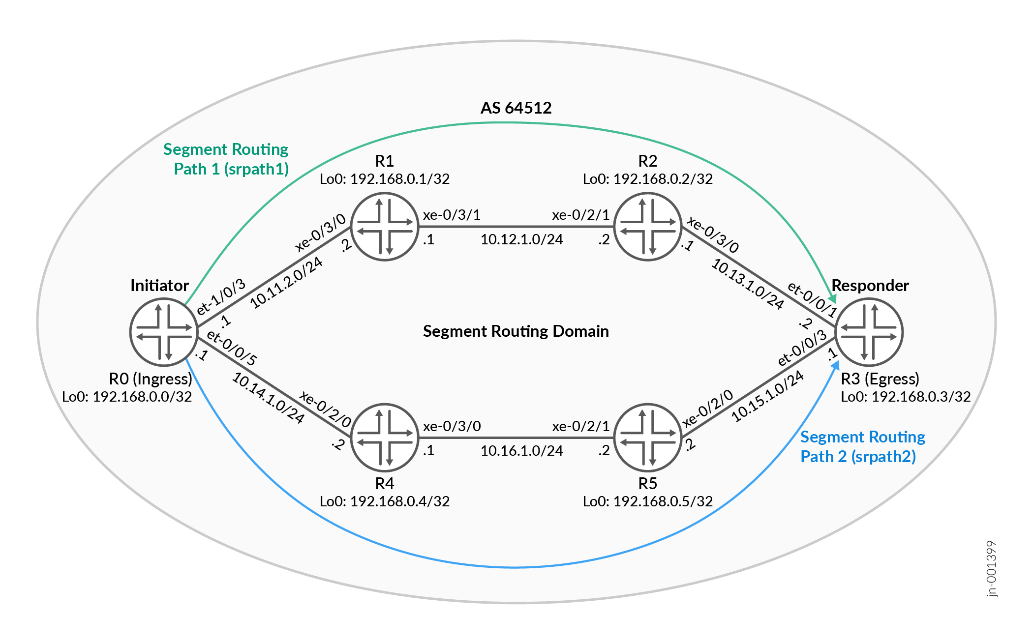
Configure S-BFD over SR-TE on R0
For complete sample configurations on the DUT, see:
Verification
Use the list of show commands to verify the feature in this example.
| Command | Verification Task |
|---|---|
| show bfd session | Verify that the BFD session is up. |
| show spring-traffic-engineering | Verify the segment routing LSP using the lsp
command option and the auto derived RD value using the
sbfd command option. |
| show bfd seamless session | Verify the S-BFD session on Device R3. |
- BFD Session Verification
- LSP Path Verification
- S-BFD Session Verification on Device R0
- S-BFD Session Verification on Device R3
BFD Session Verification
Purpose
Verify the status of the BFD session.
Action
From operational mode, enter the show bfd session extensive command to view the status of the BFD session.
user@R0> show bfd session extensive
                                                  Detect   Transmit
Address                  State     Interface      Time     Interval  Multiplier
127.0.0.1                Up                     0.000     2.000        3
 Client SPRING-TE, TX interval 1.000, RX interval 1.000
 Local diagnostic None, remote diagnostic None
 Remote state AdminDown, version 1
 Replicated
 Session type: Multi hop BFD (Seamless)
 Min async interval 1.000, min slow interval 2.000
 Adaptive async TX interval 2.000, RX interval 2.000
 Local min TX interval 2.000, minimum RX interval 1.000, multiplier 3
 Remote min TX interval 0.000, min RX interval 0.000, multiplier 0
 Local discriminator 18, remote discriminator 3232235523
 Echo TX interval 2.000, echo detection interval 6.000
 Echo mode disabled/inactiveno-absorb, no-refresh
 Path-Name V4-srte_bfd_session-4
  Session ID: 0

                                                  Detect   Transmit
Address                  State     Interface      Time     Interval  Multiplier
127.0.0.1                Up                       3.000     1.000        3
 Client SPRING-TE, TX interval 1.000, RX interval 1.000
 Session up time 00:18:16
 Local diagnostic None, remote diagnostic None
 Remote state Up, version 1
 Replicated
 Session type: Multi hop BFD (Seamless)
 Min async interval 1.000, min slow interval 1.000
 Adaptive async TX interval 1.000, RX interval 1.000
 Local min TX interval 1.000, minimum RX interval 1.000, multiplier 3
 Remote min TX interval 1.000, min RX interval 0.000, multiplier 3
 Local discriminator 17, remote discriminator 3232235523
 Echo TX interval 0.000, echo detection interval 0.000
 Echo mode disabled/inactive
 Remote is control-plane independent
 Path-Name V4-srte_bfd_session-3
  Session ID: 0

2 sessions, 2 clients
Cumulative transmit rate 1.5 pps, cumulative receive rate 1.0 pps
Meaning
The status of the BFD sessions are up.
The sessions are named as V4-srte_bfd_session-4 and
V4-srte_bfd_session-3. Because many LSPs can share the
same BFD session, when the first LSP with a unique combination of
label-stack + address-family comes up, S-BFD uses the
address-family + lsp-name combination for the session
name. If later, more LSPs share the same session, the name of the session
can change to address-family + least-lsp-name, without
affecting the state of the S-BFD session.
LSP Path Verification
Purpose
Verify that the segment routing LSP (srlsp1) is configured and the S-BFD session status is visible. Verify the path that srlsp1 is traversing to reach Device R3.
Action
From the operational mode, enter the show spring-traffic-engineering lsp name srlsp1 detail command to understand the path the segment routing LSP is traversing.
user@R0> show spring-traffic-engineering lsp name srlsp1 detail
E = Entropy-label Capability

Name: srlsp1
  Tunnel-source: Static configuration
  Tunnel Forward Type: SRMPLS
  To: 192.168.0.3
  Te-group-id: 0
  State: Up
    Path: srpath1
    Path Status: NA
    Outgoing interface: NA
    Auto-translate status: Enabled Auto-translate result: Success
    Compute Status:Disabled , Compute Result:N/A , Compute-Profile Name:N/A
    BFD status: Up BFD name: V4-srte_bfd_session-3
    BFD remote-discriminator: 3232235523(auto-derived)
    Segment ID : 128
    ERO Valid: true
      SR-ERO hop count: 3
        Hop 1 (Strict):
          NAI: IPv4 Adjacency ID, 0.0.0.0 -> 10.11.2.2
          SID type: 20-bit label, Value: 16
        Hop 2 (Loose):
          NAI: IPv4 Node ID, Node address: 192.168.0.2
          SID type: 20-bit label, Value: 801002
        Hop 3 (Loose):
          NAI: IPv4 Node ID, Node address: 192.168.0.3
          SID type: 20-bit label, Value: 801003
    Path: srpath2
    Path Status: NA
    Outgoing interface: NA
    Auto-translate status: Enabled Auto-translate result: Success
    Compute Status:Disabled , Compute Result:N/A , Compute-Profile Name:N/A
    BFD status: Down BFD name: V4-srte_bfd_session-4
    BFD remote-discriminator: 3232235523(auto-derived)
    Segment ID : 256
    ERO Valid: true
      SR-ERO hop count: 1
        Hop 1 (Strict):
          NAI: IPv4 Adjacency ID, 0.0.0.0 -> 10.14.1.2
          SID type: 20-bit label, Value: 17


Total displayed LSPs: 1 (Up: 1, Down: 0, Initializing: 0)
Meaning
Verify the hops the LSP is traversing to reach the last hop, Device R3.
Output for each LSP shows the S-BFD status as well as the S-BFD name it is referring to. Because there might not be one S-BFD session per LSP, the LSP-level S-BFD counters are not displayed.
S-BFD Session Verification on Device R0
Purpose
Verify the status of the S-BFD sessions over the two segment routing paths on Device R0.
Action
From the operational mode, enter the show spring-traffic-engineering sbfd detailcommand to verify the status of the S-BFD session.
user@R0> show spring-traffic-engineering sbfd detail
BFD name: V4-srte_bfd_session-4
BFD status: Up
BFD remote-discriminator: 3232235523
BFD local-discriminator: 18
Referencing LSPs:
  srlsp1:srpath2
      SR-ERO hop count: 1
        Hop 1 (Strict):
          NAI: IPv4 Adjacency ID, 0.0.0.0 -> 10.14.1.2
          SID type: 20-bit label, Value: 17

BFD name: V4-srte_bfd_session-3
BFD status: Up
BFD remote-discriminator: 3232235523
BFD local-discriminator: 17
Referencing LSPs:
  srlsp1:srpath1
      SR-ERO hop count: 3
        Hop 1 (Strict):
          NAI: IPv4 Adjacency ID, 0.0.0.0 -> 10.11.2.2
          SID type: 20-bit label, Value: 16
        Hop 2 (Loose):
          NAI: IPv4 Node ID, Node address: 192.168.0.2
          SID type: 20-bit label, Value: 801002
        Hop 3 (Loose):
          NAI: IPv4 Node ID, Node address: 192.168.0.3
          SID type: 20-bit label, Value: 801003


Total displayed BFD sessions: 2 (Up: 2, Down: 0)
Meaning
The S-BFD sessions are up and Device R0 can reach Device R3.
S-BFD Session Verification on Device R3
Purpose
Verify the status of the S-BFD sessions on the BFD responder, Device R3.
Action
From the operational mode, enter the show bfd seamless session extensivecommand to verify the status of the S-BFD session.
user@R3> show bfd seamless session extensive
                                                                                                     Receive
Type     Descriminator                Table      Address                                    State    Interval
Local    3232235523 (192.168.0.3)       default                                             Up       0.050
 Logical system id 0, Route table id 0
 ISSU State: false
 Authentication: false

1 local sessions, 0 remote sessions
Meaning
The S-BFD session is up and the configured BFD local discriminator corresponds with the BFD remote discriminator value.
Appendix 1: Set Commands on All Devices
R0
set system host-name R1
set chassis network-services enhanced-ip
set interfaces et-0/0/5 unit 0 description "CONNECTED TO R4"
set interfaces et-0/0/5 unit 0 family inet address 10.14.1.1/24
set interfaces et-0/0/5 unit 0 family iso
set interfaces et-0/0/5 unit 0 family mpls
set interfaces et-1/0/3 unit 0 description "CONNECTED TO R1"
set interfaces et-1/0/3 unit 0 family inet address 10.11.2.1/24
set interfaces et-1/0/3 unit 0 family iso
set interfaces et-1/0/3 unit 0 family mpls
set interfaces lo0 unit 0 family inet address 192.168.0.0/32
set interfaces lo0 unit 0 family iso address 49.0001.000a.0a0a.0a00
set policy-options policy-statement prefix-sid term 1 from route-filter 192.168.0.0/32 exact
set policy-options policy-statement prefix-sid term 1 then prefix-segment index 100
set policy-options policy-statement prefix-sid term 1 then prefix-segment node-segment
set policy-options policy-statement prefix-sid term 1 then accept
set routing-options router-id 192.168.0.0
set routing-options autonomous-system 64512
set routing-options rib-groups test import-rib inet.0
set routing-options rib-groups test import-rib inet.3
set protocols isis interface et-0/0/5.0 level 2 metric 20
set protocols isis interface et-0/0/5.0 node-link-protection
set protocols isis interface et-0/0/5.0 point-to-point
set protocols isis interface et-1/0/3.0 level 2 metric 20
set protocols isis interface et-1/0/3.0 node-link-protection
set protocols isis interface et-1/0/3.0 point-to-point
set protocols isis interface all ldp-synchronization
set protocols isis interface all node-link-protection
set protocols isis interface fxp0.0 disable
set protocols isis interface lo0.0 disable
set protocols isis source-packet-routing adjacency-segment hold-time 240000
set protocols isis source-packet-routing srgb start-label 800000
set protocols isis source-packet-routing srgb index-range 80000
set protocols isis source-packet-routing explicit-null
set protocols isis source-packet-routing traffic-statistics statistics-granularity per-interface
set protocols isis level 1 disable
set protocols isis level 2 wide-metrics-only
set protocols isis level 2 preference 180
set protocols isis backup-spf-options remote-backup-calculation
set protocols isis backup-spf-options use-source-packet-routing
set protocols isis traffic-engineering l3-unicast-topology
set protocols isis traffic-engineering family inet shortcuts
set protocols isis export prefix-sid
set protocols isis ignore-attached-bit
set protocols isis rib-group inet test
set protocols mpls interface all
set protocols mpls interface fxp0.0 disable
set protocols source-packet-routing segment-list srpath1 auto-translate unprotected
set protocols source-packet-routing segment-list srpath1 hop1 ip-address 10.11.2.2
set protocols source-packet-routing segment-list srpath1 hop2 ip-address 192.168.0.2
set protocols source-packet-routing segment-list srpath1 hop2 label-type node
set protocols source-packet-routing segment-list srpath1 hop3 ip-address 192.168.0.3
set protocols source-packet-routing segment-list srpath1 hop3 label-type node
set protocols source-packet-routing segment-list srpath2 auto-translate unprotected
set protocols source-packet-routing segment-list srpath2 hop1 ip-address 10.14.1.2
set protocols source-packet-routing source-routing-path srlsp1 to 192.168.0.3
set protocols source-packet-routing source-routing-path srlsp1 primary srpath1 weight 23
set protocols source-packet-routing source-routing-path srlsp1 primary srpath1 bfd-liveness-detection sbfd
set protocols source-packet-routing source-routing-path srlsp1 primary srpath1 bfd-liveness-detection minimum-interval 1000
set protocols source-packet-routing source-routing-path srlsp1 primary srpath2 weight 45
set protocols source-packet-routing source-routing-path srlsp1 primary srpath2 bfd-liveness-detection sbfd
set protocols source-packet-routing source-routing-path srlsp1 primary srpath2 bfd-liveness-detection minimum-interval 1000
set protocols source-packet-routing inherit-label-nexthops
R1
set system host-name R1
set chassis network-services enhanced-ip
set interfaces xe-0/3/0 unit 0 description "CONNECTED TO R0"
set interfaces xe-0/3/0 unit 0 family inet address 10.11.2.2/24
set interfaces xe-0/3/0 unit 0 family iso
set interfaces xe-0/3/0 unit 0 family mpls
set interfaces xe-0/3/1 unit 0 description "CONNECTED TO R2"
set interfaces xe-0/3/1 unit 0 family inet address 11.12.1.1/24
set interfaces xe-0/3/1 unit 0 family iso
set interfaces xe-0/3/1 unit 0 family mpls
set interfaces lo0 unit 0 family inet address 192.168.0.1/32
set interfaces lo0 unit 0 family iso address 49.0001.0001.0101.0100
set policy-options policy-statement prefix-sid term 1 from route-filter 192.168.0.1/32 exact
set policy-options policy-statement prefix-sid term 1 then prefix-segment index 1001
set policy-options policy-statement prefix-sid term 1 then prefix-segment node-segment
set policy-options policy-statement prefix-sid term 1 then accept
set routing-options router-id 192.168.0.1
set routing-options autonomous-system 64512
set routing-options rib-groups test import-rib inet.0
set routing-options rib-groups test import-rib inet.3
set protocols isis backup-spf-options remote-backup-calculation
set protocols isis backup-spf-options use-source-packet-routing
set protocols isis backup-spf-options per-prefix-calculation
set protocols isis traffic-engineering family inet shortcuts
set protocols isis source-packet-routing adjacency-segment hold-time 240000
set protocols isis source-packet-routing srgb start-label 800000
set protocols isis source-packet-routing srgb index-range 80000
set protocols isis source-packet-routing explicit-null
set protocols isis level 1 disable
set protocols isis level 1 wide-metrics-only
set protocols isis level 2 wide-metrics-only
set protocols isis interface xe-0/3/0.0 point-to-point
set protocols isis interface xe-0/3/0.0 node-link-protection
set protocols isis interface xe-0/3/1.0 point-to-point
set protocols isis interface xe-0/3/1.0 node-link-protection
set protocols isis interface all node-link-protection
set protocols isis interface em0.0 disable
set protocols isis interface fxp0.0 disable
set protocols isis export prefix-sid
set protocols isis ignore-attached-bit
set protocols isis rib-group inet test
set protocols mpls traffic-engineering
set protocols mpls interface all
R2
set system host-name R2
set chassis network-services enhanced-ip
set interfaces xe-0/2/1 unit 0 description "CONNECTED TO R1"
set interfaces xe-0/2/1 unit 0 family inet address 11.12.1.2/24
set interfaces xe-0/2/1 unit 0 family iso
set interfaces xe-0/2/1 unit 0 family mpls
set interfaces xe-0/3/0 unit 0 description "CONNECTED TO R3"
set interfaces xe-0/3/0 unit 0 family inet address 12.13.1.1/24
set interfaces xe-0/3/0 unit 0 family iso
set interfaces xe-0/3/0 unit 0 family mpls
set interfaces lo0 unit 0 family inet address 192.168.0.2/32
set interfaces lo0 unit 0 family iso address 49.0001.0002.0202.0200
set policy-options policy-statement prefix-sid term 1 from route-filter 192.168.0.2/32 exact
set policy-options policy-statement prefix-sid term 1 then prefix-segment index 1002
set policy-options policy-statement prefix-sid term 1 then prefix-segment node-segment
set policy-options policy-statement prefix-sid term 1 then accept
set routing-options router-id 192.168.0.2
set routing-options autonomous-system 64512
set protocols isis backup-spf-options remote-backup-calculation
set protocols isis backup-spf-options use-source-packet-routing
set protocols isis traffic-engineering family inet shortcuts
set protocols isis source-packet-routing adjacency-segment hold-time 240000
set protocols isis source-packet-routing srgb start-label 800000
set protocols isis source-packet-routing srgb index-range 80000
set protocols isis source-packet-routing explicit-null
set protocols isis level 1 disable
set protocols isis level 1 wide-metrics-only
set protocols isis level 2 wide-metrics-only
set protocols isis interface xe-0/2/1.0 point-to-point
set protocols isis interface xe-0/2/1.0 node-link-protection
set protocols isis interface xe-0/3/0.0 point-to-point
set protocols isis interface xe-0/3/0.0 node-link-protection
set protocols isis interface all node-link-protection
set protocols isis interface em0.0 disable
set protocols isis interface fxp0.0 disable
set protocols isis interface lo0.0 passive
set protocols isis export prefix-sid
set protocols isis ignore-attached-bit
set protocols mpls interface all
R3
set system host-name R3
set chassis network-services enhanced-mode
set interfaces et-0/0/1 unit 0 description "CONNECTED TO R2"
set interfaces et-0/0/1 unit 0 family inet address 12.13.1.2/24
set interfaces et-0/0/1 unit 0 family iso
set interfaces et-0/0/1 unit 0 family mpls
set interfaces et-0/0/3 unit 0 description "CONNECTED TO R5"
set interfaces et-0/0/3 unit 0 family inet address 10.15.1.1/24
set interfaces et-0/0/3 unit 0 family iso
set interfaces et-0/0/3 unit 0 family mpls
set interfaces lo0 unit 0 family inet address 192.168.0.3/32
set interfaces lo0 unit 0 family iso address 49.0001.0003.0303.0300
set policy-options policy-statement prefix-sid term 1 from route-filter 192.168.0.3/32 exact
set policy-options policy-statement prefix-sid term 1 then prefix-segment index 1003
set policy-options policy-statement prefix-sid term 1 then prefix-segment node-segment
set policy-options policy-statement prefix-sid term 1 then accept
set routing-options router-id 192.168.0.3
set routing-options autonomous-system 64512
set protocols bfd sbfd local-discriminator-ip 192.168.0.3
set protocols isis interface et-0/0/1.0 node-link-protection
set protocols isis interface et-0/0/1.0 point-to-point
set protocols isis interface et-0/0/3.0 node-link-protection
set protocols isis interface et-0/0/3.0 point-to-point
set protocols isis interface all ldp-synchronization
set protocols isis interface all node-link-protection
set protocols isis interface em0.0 disable
set protocols isis interface fxp0.0 disable
set protocols isis interface lo0.0 passive
set protocols isis source-packet-routing adjacency-segment hold-time 240000
set protocols isis source-packet-routing srgb start-label 800000
set protocols isis source-packet-routing srgb index-range 80000
set protocols isis source-packet-routing explicit-null
set protocols isis level 1 disable
set protocols isis level 1 wide-metrics-only
set protocols isis level 2 wide-metrics-only
set protocols isis backup-spf-options remote-backup-calculation
set protocols isis backup-spf-options use-source-packet-routing
set protocols isis export prefix-sid
set protocols isis ignore-attached-bit
set protocols mpls interface all
R4
set system host-name R4
set chassis network-services enhanced-ip
set interfaces xe-0/2/0 description "CONNECTED TO R0"
set interfaces xe-0/2/0 unit 0 family inet address 10.14.1.2/24
set interfaces xe-0/2/0 unit 0 family iso
set interfaces xe-0/2/0 unit 0 family mpls
set interfaces xe-0/3/0 unit 0 description "CONNECTED TO R5"
set interfaces xe-0/3/0 unit 0 family inet address 10.15.1.1/24
set interfaces xe-0/3/0 unit 0 family iso
set interfaces xe-0/3/0 unit 0 family mpls
set interfaces lo0 unit 0 family inet address 192.168.0.4/32
set interfaces lo0 unit 0 family iso address 49.0001.0004.0404.0400
set policy-options policy-statement prefix-sid term 1 from route-filter 192.168.0.4/32 exact
set policy-options policy-statement prefix-sid term 1 then prefix-segment index 1004
set policy-options policy-statement prefix-sid term 1 then prefix-segment node-segment
set policy-options policy-statement prefix-sid term 1 then accept
set routing-options router-id 192.168.0.4
set routing-options autonomous-system 64512
set protocols isis backup-spf-options remote-backup-calculation
set protocols isis backup-spf-options use-source-packet-routing
set protocols isis traffic-engineering family inet-mpls shortcuts
set protocols isis traffic-engineering family inet shortcuts
set protocols isis source-packet-routing adjacency-segment hold-time 240000
set protocols isis source-packet-routing srgb start-label 800000
set protocols isis source-packet-routing srgb index-range 80000
set protocols isis source-packet-routing explicit-null
set protocols isis level 1 disable
set protocols isis level 1 wide-metrics-only
set protocols isis level 2 wide-metrics-only
set protocols isis interface xe-0/2/0.0 point-to-point
set protocols isis interface all node-link-protection
set protocols isis interface all ldp-synchronization
set protocols isis interface em0.0 disable
set protocols isis interface fxp0.0 disable
set protocols isis interface lo0.0 passive
set protocols isis export prefix-sid
set protocols isis ignore-attached-bit
set protocols isis suppress-attached-bit
set protocols mpls interface all
R5
set system host-name R5
set chassis network-services enhanced-ip
set interfaces xe-0/2/0 unit 0 description "CONNECTED To R3"
set interfaces xe-0/2/0 unit 0 family inet address 10.15.1.2/24
set interfaces xe-0/2/0 unit 0 family iso
set interfaces xe-0/2/0 unit 0 family mpls
set interfaces xe-0/2/1 unit 0 description "CONNECTED To R4"
set interfaces xe-0/2/1 unit 0 family inet address 10.16.1.2/24
set interfaces xe-0/2/1 unit 0 family iso
set interfaces xe-0/2/1 unit 0 family mpls
set interfaces lo0 unit 0 family inet address 192.168.0.5/32
set interfaces lo0 unit 0 family iso address 49.0001.0005.0505.0500
set policy-options policy-statement prefix-sid term 1 from route-filter 192.168.0.5/32 exact
set policy-options policy-statement prefix-sid term 1 then prefix-segment index 1005
set policy-options policy-statement prefix-sid term 1 then prefix-segment node-segment
set policy-options policy-statement prefix-sid term 1 then accept
set routing-options router-id 192.168.0.5
set routing-options autonomous-system 64512
set protocols isis backup-spf-options remote-backup-calculation
set protocols isis backup-spf-options use-source-packet-routing
set protocols isis traffic-engineering family inet shortcuts
set protocols isis source-packet-routing adjacency-segment hold-time 240000
set protocols isis source-packet-routing srgb start-label 800000
set protocols isis source-packet-routing srgb index-range 80000
set protocols isis source-packet-routing explicit-null
set protocols isis level 1 disable
set protocols isis level 1 wide-metrics-only
set protocols isis level 2 wide-metrics-only
set protocols isis interface xe-0/2/0.0 point-to-point
set protocols isis interface xe-0/2/1.0 point-to-point
set protocols isis interface all node-link-protection
set protocols isis interface all ldp-synchronization
set protocols isis interface em0.0 disable
set protocols isis interface fxp0.0 disable
set protocols isis interface lo0.0 passive
set protocols isis export prefix-sid
set protocols isis ignore-attached-bit
set protocols mpls interface all
Appendix 2: Show Configuration Output on R0
Show configuration output on Device R0.
user@R0# show interfaces
et-0/0/5 {
    unit 0 {
        description "CONNECTED TO R4";
        family inet {
            address 10.14.1.1/24;
        }
        family iso;
        family mpls;
    }
}
et-1/0/3 {
    unit 0 {
        description "CONNECTED TO R1";
        family inet {
            address 10.11.2.1/24;
        }
        family iso;
        family mpls;
    }
}
lo0 {
    unit 0 {
        family inet {
            address 192.168.0.0/32;
        }
        family iso {
            address 49.0001.000a.0a0a.0a00;
        }
    }
}
usre@R0# show policy-options
policy-statement prefix-sid {
    term 1 {
        from {
            route-filter 192.168.0.0/32 exact;
        }
        then {
            prefix-segment {
                index 100;
                node-segment;
            }
            accept;
        }
    }
}user@R0# show routing-options
router-id 192.168.0.0;
autonomous-system 64512;
rib-groups {
test {
import-rib [ inet.0 inet.3 ];
}
}user@R0# show protocols
isis {
interface et-0/0/5.0 {
level 2 metric 20;
node-link-protection;
point-to-point;
}
interface et-1/0/3.0 {
level 2 metric 20;
node-link-protection;
point-to-point;
}
interface all {
ldp-synchronization;
node-link-protection;
}
interface fxp0.0 {
disable;
}
interface lo0.0 {
disable;
}
source-packet-routing {
adjacency-segment hold-time 240000;
srgb start-label 800000 index-range 80000;
explicit-null;
traffic-statistics {
statistics-granularity per-interface;
}
}
level 1 disable;
level 2 {
wide-metrics-only;
preference 180;
}
backup-spf-options {
remote-backup-calculation;
use-source-packet-routing;
}
traffic-engineering {
l3-unicast-topology;
family inet {
shortcuts;
}
}
export prefix-sid;
ignore-attached-bit;
rib-group inet test;
}
mpls {
interface all;
interface fxp0.0 {
disable;
}
}
source-packet-routing {
segment-list srpath1 {
auto-translate {
unprotected;
}
hop1 ip-address 10.11.2.2;
hop2 {
ip-address 192.168.0.2;
label-type {
node;
}
}
hop3 {
ip-address 192.168.0.3;
label-type {
node;
}
}
}
segment-list srpath2 {
auto-translate {
unprotected;
}
hop1 ip-address 10.14.1.2;
}
source-routing-path srlsp1 {
to 192.168.0.3;
primary {
srpath1 {
weight 23;
bfd-liveness-detection {
sbfd;
minimum-interval 1000;
}
}
srpath2 {
weight 45;
bfd-liveness-detection {
sbfd;
minimum-interval 1000;
}
}
}
}
inherit-label-nexthops;
}Configuring Static Adjacency Segment Identifier for Aggregate Ethernet Member Links Using Single-Hop Static LSP
In a network where aggregate Ethernet (AE) bundles are in use, an aggregate link could be a bundle of any number of physical links. The traffic sent over these AE bundle interfaces are forwarded on any of the member links of an AE interface. The traffic can take any physical link based on the hash defined for load-balancing the traffic, which makes it difficult to isolate which links have gone bad or are dropping the traffic. One way to test the forwarding path available in the network is to add a single-hop static label switched path (LSP) with the next hop pointing to a specific member link of the AE interface.
The default label operation for the static LSPs must be pop and forward. When a packet hits these labeled routes, the packet is forwarded on to a specific member link. A unique label is used to identify the member link. These labels are referred to as adjacency segment identifiers (SID) and are statically provisioned.
You can control the flow of the packets in the network by constructing a label stack in controller, which includes the labels allocated by all transit static LSP. Operation, Administration, and Maintenance (OAM) packets are crafted and injected into the network with entire label-stack.
When a packet hits this label route the label is popped and traffic is forwarded on the member link specified in the configuration. A destination MAC is chosen while forwarding the packet, the destination Mac is the aggregate interface MAC address (selected based on nexthop address configured).
When the member link goes down and aggregate interface is up, then the route corresponding to that member link is deleted. When an aggregate interface goes down, then all the routes corresponding to member links of the aggregate interface are deleted. When the child physical interface is LACP detached but the child physical interface is up, the labeled route for the child link is deleted. In the case of LACP detach, if the member link is up and invalid forwarding state, then the OAM packets is dropped in the PFE when the child physical interface is detached.
Use the following example to configure single-hop static LSP for an AE member link.
Define a static label range.
user@host# set protocols mpls label-range static-label-range 1000000 1048575;Note:We recommend configuring the default static label range of 1000000-1048575 for the static LSP. If you wish to configure a label range other than the default static label range, configure multiple ranges.
Create a static LSP for the AE member link from the segment routing local block (SRLB) pool of the static label range.
user@host# set protocols mpls static-label-switched-path statc-lsp transit 100001 pop next-hop 10.1.1.1 member-interface ge-0/0/0
In this configuration, a transit labelled router is installed in mpls.0, pops the label, and forwards the packet down the next hop. The next hop address is mandatory for broadcast interfaces (such as ge-, xe-, ae-) and the if-name is used for P2P interfaces (such as so-). The address is required for broadcast interfaces because the next hop IP address is used to pick the destination MAC address. The source MAC address for the packet is the AE’s MAC address.
The sample outputs display the member link name in the next hop output:
show mpls static-lsp extensive
user@host> show mpls static-lsp extensive
Ingress LSPs:
Total 0, displayed 0, Up 0, Down 0

Transit LSPs:
LSPname: static-lsp1, Incoming-label: 1000001
  Description: verify-static-lsp-behavior
  State: Up, Sub State: Traffic via primary but unprotected
  Nexthop: 10.2.1.1 Via ae0.0 -> ge-0/0/0
  LabelOperation: Pop
  Created: Thu May 25 15:31:26 2017
  Bandwidth: 0 bps
  Statistics: Packets 0, Bytes 0
show route label label-name extensive
user@host> show route label 1000001 extensive

mpls.0: 14 destinations, 14 routes (14 active, 0 holddown, 0 hidden)
1000001 (1 entry, 1 announced)
TSI:
KRT in-kernel 1000001/52 -> {Pop      }
        *MPLS   Preference: 6
                Next hop type: Router, Next hop index: 611
                Address: 0xb7a17b0
                Next-hop reference count: 2
                Next hop: 10.2.1.1 via ae0.0 -> ge-0/0/0 weight 0x1, selected
                Label operation: Pop
                Load balance label: None;
                Label element ptr: 0xb7a1800
                Label parent element ptr: 0x0
                Label element references: 1
                Label element child references: 0
                Label element lsp id: 0
                Session Id: 0x15d
                State: <Active Int>
                Age: 3:13:15    Metric: 1
                Validation State: unverified
                Task: MPLS
                Announcement bits (1): 1-KRT
                AS path: I
                Label 188765184
Non-Router-ID Endpoints in Segment Routing Traffic Engineering
Historically, RSVP‑TE supported non‑router‑ID endpoints. Adding non-router-ID endpoints into Segment Routing Traffic Engineering (SR-TE) policies enhances your network's flexibility and efficiency across both IPv4 and IPv6 within SR-MPLS frameworks. The non-router-ID endpoint in SR-TE allows ingress routers to steer traffic to logical destinations (for example, anycast service address) rather than being constrained to node router‑IDs. By enabling the specifications of anycast, secondary loopback (lo0), and interface prefix addresses as destination points, you can achieve robust load-balancing and redundancy.
Traditionally, SR-TE policies use router IDs, but you can specify anycast addresses to enhance redundancy and load balancing in SR-MPLS networks. Use IPv4 and IPv6 anycast addresses as IGP-learned destinations with or without SID stack compression. These anycast addresses are not redistributed (R-bit set). Use them as the to address for SR-TE policies with associated compute profiles.
Benefits of Non-Router-ID Endpoints for SR-TE
-
Enhances network flexibility by targeting multiple nodes advertising a shared prefix, facilitating effective load-balancing and redundancy.
-
Expands SR-TE configurations with anycast addresses, providing more options for network design and optimization.
-
Improves packet ingress control without additional traffic engineering constraints, allowing efficient network management.
-
Optimizes routing paths for robust network performance, ensuring seamless traffic distribution and improved resilience.
Anycast as a Destination Address
Multiple nodes can advertise a single anycast IP address (IPv4 or IPv6) and corresponding anycast SIDs throughout an IGP domain.
An anycast SID is a type of prefix SID that identifies a set of nodes. The set of nodes (anycast group) is configured to advertise a shared prefix address and prefix SID. Anycast routing enables the steering of traffic toward multiple advertising nodes, providing load-balancing and redundancy. Packets addressed to an anycast address are forwarded to the topologically nearest nodes.
An ingress router is configured with an SR-TE policy using the anycast IP address (IPv4 or IPv6) as the endpoint.
Use the show spring-traffic-engineering detail command to view
comprehensive details on non-router-ID endpoints, showing computed segments and anycast SID
details. Use these commands to ensure SR-TE policies are correctly implemented, achieving
seamless traffic distribution and optimized routing paths.
Computing Delay Optimized Intradomain and Interdomain Segment Routing Paths
- Delay-based Metrics for Traffic Engineered Paths Overview
- Benefits of Delay-based Metrics for Path Computation
- DCSPF-based Computation with Delay Metrics for SR Path Overview
- Delay Metrics for Interdomain and Intradomain Use Case Overview
- Delay Metrics in Optical Networks Use Case
Delay-based Metrics for Traffic Engineered Paths Overview
Leveraging dynamic delay-based metrics is becoming a desirable attribute in modern networks. Delay-based metrics is essential for a Path Computation Element (PCE) to compute traffic engineered paths. You can use delay-based metrics to steer packets on the least latency paths, or the least delay path. To do this, you need to measure the delay on every link and advertise it using a suitable routing protocol (IGP or BGP-LS), so that the ingress has the per link delay properties in its TED.
To understand how to advertise the delay on each link, or turn on link measurements, see How to Enable Link Delay Measurement and Advertising in IS-IS.
The following sequence of events happen when you measure, advertise, and compute the detection of changes in the network and calculate traffic engineered path with shortest latency:
- Detect changes in the network by measuring the latency, with synthetic probes, router-to-router.
- Flood the results to ingress nodes through IGP extended TE-metric extensions.
- Advertise the results to centralized controllers with corresponding BGP-LS extensions.
- Compute IGP-based shortest cumulative latency metric paths (Flex-algo).
- Compute traffic-engineered explicit paths (source to destination) with shortest cumulative latency or delay metrics (SR-TE).
Benefits of Delay-based Metrics for Path Computation
- Deploy value-added services based on the lowest latency throughout the network.
- Measure per path latency (minimum, maximum, average) using delay-based metrics.
- Steer delay sensitive services (such as VPN or 5G services) on ultra-low latency SR optimized paths.
DCSPF-based Computation with Delay Metrics for SR Path Overview
Using the distributed Constrained Shortest Path First (CSPF) for segment routing LSP feature, you can compute a segment routing LSP locally on the ingress device according to the constraints you have configured. With this feature, the LSPs are optimized based on the configured constraints and metric type (traffic-engineering or IGP). The LSPs are computed to utilize the available ECMP paths to the destination with segment routing label stack compression enabled or disabled.
You can configure distributed CSFP to run on multiple headends and do path computation independently on each headend. You can apply compute profile on the source path (source packet routing path). If you have configured compute profile optimized for delay average, you can also additionally apply a constraint called the delay-variation-threshold. When you configure a value for delay-variation-threshold, any link exceeding the threshold value would be excluded from path computation.
To configure delay metrics for DCSPF-based computation for SR path, you need to enable the delay configuration statement at the [edit protocols source-packet-routing compute-profile profile-name metric-type delay] hierarchy level. You can configure the delay metrics such as minimum, maximum, average, and delay variation threshold for path calculation.
-
minimum—Minimum delay metric value from TED for cumulative lowest latency path calculation. -
average—Average delay metric value from TED for cumulative lowest latency path calculation. -
maximum—Maximum delay metric value from TED for cumulative lowest latency path calculation. -
delay-variation-threshold—Link delay variation threshold (1..16777215). Any link exceeding the delay variation threshold would be excluded from path calculation. The delay variation threshold is independent of whether you are doing optimization for minimum, maximum, or average. Thedelay-variation-thresholdconfiguration statement appears at these hierarchy levels:-
[
edit protocols source-packet-routing compute-profile
                                        profile-name metric-type
                                delay
] -
[
edit protocols source-packet-routing compute-profile
                                        profile-name metric-type delay
                                    minimum
] -
[
edit protocols source-packet-routing compute-profile
                                        profile-name metric-type delay
                                    maximum
] -
[
edit protocols source-packet-routing compute-profile
                                        profile-name metric-type delay
                                    average
]
-
-
Note: We support SR-TE local computation with OSPF as the underlay IGP for
delay metric.
You can configure delay metrics at the following CLI hierarchy:
[edit]
protocols {
    source-packet-routing {
        compute-profile <name> {
            metric-type delay {
                  minimum;
                  maximum;
                  average;
                  delay-variation-threshold <value>;
                 }
            }
      }
}
Delay Metrics for Interdomain and Intradomain Use Case Overview
For the intra-domain case (path resides within a single domain), the link delay is taken into consideration when doing path computation. Delay metrics for segment routing path computation is supported on both compressed SIDs and uncompressed SIDs. If you have uncompressed SIDs, then adjacency segments for segment lists is used to produce multiple segment lists if there are equal costs. You can configure uncompressed SIDs using the no-label-stack-compression configuration statement at the [edit protocols source-packet-routing compute-profile profile-name ] hierarchy level. This provides a fully expanded path using adjacency SIDs. See compute-profile for more information.
The following is a sample configuration for delay metrics:
[edit protocols source-packet-routing]
user@host# show
compute-profile profile1 {
    no-label-stack-compression;
    metric-type {
        delay {
            minimum;
            delay-variation-threshold 300;
        }
    }
}
For optical path computation, it is recommended to use the delay metrics as minimum. Minimum is the default configuration.
For interdomain (multi-domain) use case, where there are multiple autonomous systems, you can use
express segments to configure link delays for path computation. Express segments are
links that connect border nodes or ASBRs. See Express Segment LSP Configuration to learn
about express segments. You can configure the delay or inherit the delay of the
underlying LSP in the express segment. You can configure delay at
the [edit protocols express-segments segment-template
template-name metric] hierarchy level and set
the values for minimum, maximum, and average delays.
You can configure delay metrics in an express segment at the following CLI hierarchy:
[edit]
protocols {
    express-segments {
        segment-template <name> {
           metric delay [ min <value> | avg <value> | max <value>
            }
        }
  }
For interdomain path computation, you can assign delay metrics on BGP EPE links. You can configure a value for delay-metric at the [edit protocols bgp group group-name neighbor ip address egress-te-adj-segment segment-name egress-te-link attribute] hierarchy level as shown below:
[edit]
protocols {
    bgp {
        group <name> {
            type external;
        }
        neighbor <ip_addr> {
            egress-te-adj-segment <name> {
                egress-te-link-attribute {
                  delay-metric <value>
                  }
                }
              }
          }
      }
Delay Metrics in Optical Networks Use Case
The following topologies depict an example of an optical use case. Optical protection and restoration solutions result in the underlying physical attributes, mainly path length, changing due to link failures and subsequent DWDM network optimization.
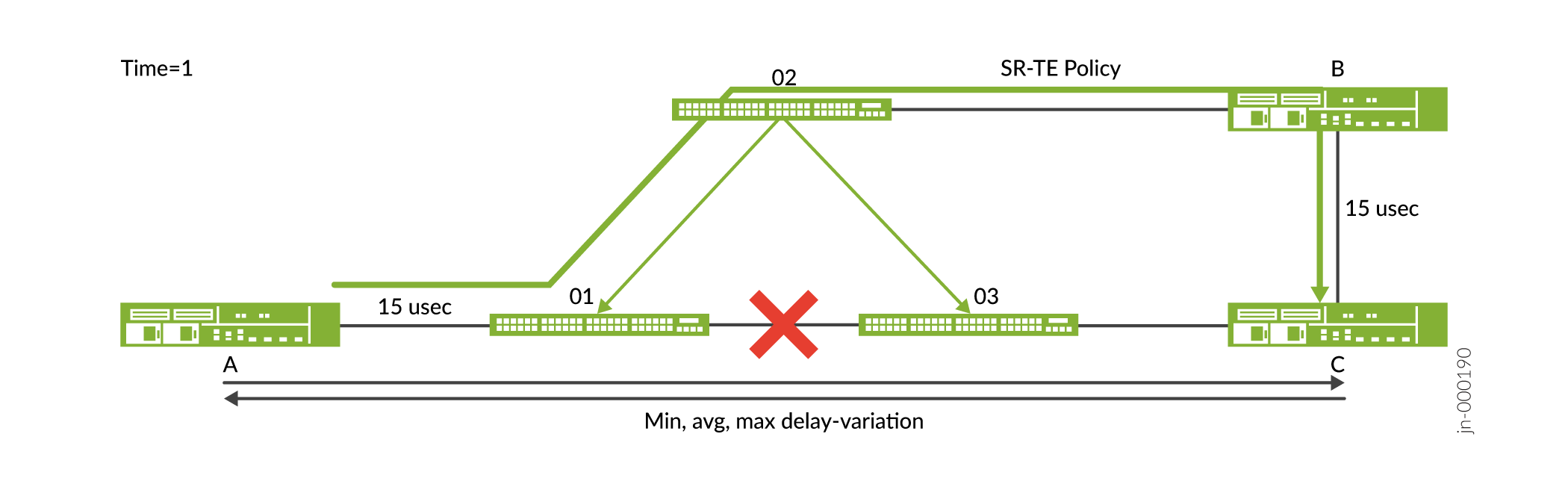
In figure, the link between A and C is through the optical nodes O1 and O3 and has a latency of 10 microseconds. In figure, you can see a link failure between optical nodes O1 and O3 and that the actual optical connection is rerouted through the optical node O2. This increases the latency of 15 microseconds. The metric for the link that connects A and B changes dynamically between time=0 and time=1.
When a change in the per link delay is detected by the ingress, the ingress triggers recomputation of the delay optimized path and the headend router reroutes the path over the next available least latency path. The change in the link delay may result in the ingress choosing another set of links that has the least latency path. In figure B, you can see there is a change in the link between the path A and C and the headend router reroutes and selects the path A-B-C as shown in the topology.
Understanding SRv6 TE Tunnel Local Path Computation
Overview
The implementation of local computation for SRv6 TE tunnels, including classical and microsegmentation SIDs (uSIDs), significantly enhances path computation capabilities within your network. By enabling local path computation, you can dynamically and efficiently compute traffic engineering paths using SRv6 SIDs based on current network topology and constraints. Configuration options allow you to enable SRv6 TE path computation, attach compute profiles, and set IGP instance and topology constraints. Additionally, preferences for SID types and support for Seamless Bidirectional Forwarding Detection (sBFD) over SRv6 TE compute tunnels ensure optimized routing and high network efficiency, making this feature integral for scalable and adaptive network design.
Benefits of SRv6 TE Tunnel Local Computation
-
Optimizes network efficiency by dynamically computing traffic engineering paths based on real-time topology and constraints, reducing unnecessary overhead and improving resource utilization.
-
Enhances scalability by supporting both classical SRv6 SIDs and uSIDs, allowing for more efficient routing and management of segment lists.
-
Facilitates adaptive routing through local computation, enabling quick adjustments to network changes without relying on external computation sources.
-
Ensures high network efficiency and reliability with support for sBFD over SRv6 TE tunnels, providing robust failure detection and response mechanisms.
Configuring SRv6 TE Tunnel Local Path Computation
To configure SRv6 TE path computation, use the following CLI configurations:
Understand BGP VPN Option C MPLS over SRv6
BGP VPN Option C with MPLS over Segment Routing for IPv6 (SRv6) enhances multi-domain network architectures by facilitating seamless interworking between SR-MPLS for IPv4 (SR-MPLS-IPv4) and SRv6 domains. This feature uses SRv6 as a transport layer, allowing you to advertise SRv6 Segment Identifiers (SIDs) alongside MPLS labels for optimal routing and forwarding.
- Benefits of BGP VPN Option C with MPLS over SRv6
- Overview
- BGP-LU LSP is Tunneled Across SRv6 Domain
- Enable SRv6 Signaling for BGP-LU Address Family
- Egress Route Behavior
- Ingress Route Behavior
- Transit Route Behavior
- Configure end-dtm-sid
- Configure advertise-srv6-service for BGP-LU Address Family
- Configure accept-srv6-service for BGP-LU address family
- Configure end-dtm-sid with Policy
Benefits of BGP VPN Option C with MPLS over SRv6
-
Enhances network scalability by enabling seamless integration of MPLS and SRv6 domains, facilitating efficient routing in multi-domain environments.
-
Improves routing flexibility through SRv6 Segment Identifiers (SIDs) alongside MPLS labels, allowing for dynamic transport scenarios and optimal packet delivery.
-
Enables precise control over routing paths with support for ingress, egress, and transit route configurations, ensuring accurate label manipulation and efficient data forwarding.
-
Increases network robustness and reliability by providing high availability support for SRv6 dynamic SIDs, minimizing service disruptions.
-
Supports advanced network operations by allowing the advertisement and acceptance of SRv6 services within BGP-LU address families, enhancing interoperability and service management across complex network setups.
Overview
Consider a multi-domain network, where there is a central domain (C) with many leaf domains around it. Service flows from an ingress PE in an ingress leaf domain (LI), through the central (C) domain and up to an egress PE of the egress leaf domain (LE). Each domain runs its own IGP instance. The leaf domains (LI and LE) use MPLS data plane (SR-MPLS-IPv4), while the central domain (C) uses SRv6 data plane.
Provider edge devices run MPLS based BGP L3 (for example, VPN) services through service route reflectors. Service endpoint signaling through borders routers and corresponding forwarding state provide interworking over intermediate transport domain. The ingress PE encapsulates the payload in an MPLS service label and sends it through MPLS LSP to egress PE. Transport nodes forward encapsulated label stack to egress PE over SRv6 C domain.
BGP Label Unicast (BGP-LU) advertises transport reachability for PE IPv4 loopbacks across the multi-domain network. Next hop self on border routers provides independence of intra domain tunnel technology in different domains. MPLS based L3 BGP services are signaled with IPv4 next-hop of egress PE through service route reflectors (RRs) with no color extended community. Ingress PE need labelled reachability to remote PE IPv4 loopback address advertised as next hop with service routes. BGP-LU advertise IPv4 PE loopbacks. Next hop self is performed on the border routers.
BGP-LU LSP is Tunneled Across SRv6 Domain
-
Existing BGP-LU label cross-connect on border routers for each PE IPv4 loopback address.
-
The lookups at the ingress border router are based on BGP-LU label.
-
SR-MPLS IGP label to next hop is replaced by an IPv6 tunnel with DA = SRv6 SID associated with DTM behavior in the SRv6 central domain.
-
Ingress border router forwarding perform label swap and H.Encaps.M with DA = SRv6 SID associated with DTM behavior.
Enable SRv6 Signaling for BGP-LU Address Family
You can enable SRv6 signaling for BGP-LU address family by:
-
Enabling
advertise-srv6-service,accept-srv6-serviceCLI statements for advertising SRv6 service TLVs for BGP-LU address family. -
Supporting SRv6 tunnel for label route of the BGP prefix-SID attribute to signal SRv6 SIDs along with MPLS label bound to prefix in NLRI. SRv6 tunnel for label route TLV is encoded exactly like SRv6 service TLVs in prefix-SID attribute.
-
Advertising end-dtm SID in BGP-LU address family without any transposition in SRv6 SID information sub-TLV of SRv6 tunnel for label route TLV in prefix-Sid attribute.
Egress Route Behavior
When end-dtm SID is configured, end-dtm SID route is added to inet6.0 table pointing to mpls.0 table nexthop with endpoint decapsulation and MPLS table lookup behavior. For end-dtm-sid, strict sid route is also added.
Ingress Route Behavior
The ingress border router performs label push and H.Encaps.M.red with IPv6 header destination address as SRv6 SID received in SRv6 tunnel for label route TLV of prefix-Sid attribute.
Transit Route Behavior
Transit border router performs label swap and H.Encaps.M.red with IPv6 header destination address as SRv6 SID received in SRv6 tunnel for label route TLV of prefix-Sid attribute.
Configure end-dtm-sid
Configure static or dynamic end-dtm-Sid. The locator can be flex algo locator.
user@host# set protocols bgp source-packet-routing srv6 locator locator-name end-dtm-sid [sid-value | non-default]
The end-dtm-sid is the endpoint with decapsulation and MPLS table lookup behavior.
The non-default sids can be applied to BGP-LU prefixes only through a policy.
Configure advertise-srv6-service for BGP-LU Address Family
If the advertise-srv6-service CLI statement is configured, then only the
SRv6 tunnel for label route TLV is advertised in BGP prefix SID attribute. The
advertise-srv6-service statement is applicable for origination. The
statement is not applicable for propagation.
user@host# set protocols bgp group internal-peers family inet labeled-unicast advertise-srv6-service
OR
user@host# set protocols bgp family inet labeled-unicast advertise-srv6-service

user@host# set protocols bgp group internal-peers family inet6 labeled-unicast advertise-srv6-service
OR
user@host# set protocols bgp family inet6 labeled-unicast advertise-srv6-service
Configure accept-srv6-service for BGP-LU address family
If the accept-srv6-service CLI statement is configured, then only SRv6
tunnel for label route TLV present in BGP prefix SID attribute is accepted.
user@host# set protocols bgp group internal-peers family inet labeled-unicast accept-srv6-service
OR
user@host# set protocols bgp family inet labeled-unicast accept-srv6-service

user@host# set protocols bgp group internal-peers family inet6 labeled-unicast accept-srv6-service
OR
user@host# set protocols bgp family inet6 labeled-unicast accept-srv6-service
Configure end-dtm-sid with Policy
The SRv6 CLI statement is enhanced to configure the SRv6 SID type: end-dtm-sid.
user@host# set policy-options policy-statement policy-name term term-name then srv6 end-dtm-sid
Platform-Specific Segment Routing LSP Behavior
Use Feature Explorer to confirm platform and release support for specific features.
Use the following table to review platform-specific behaviors for your platform:
Platform-Specific Segment Routing LSP Behavior
| Platform | Difference |
|---|---|
|
ACX Series |
|
Change History Table
Feature support is determined by the platform and release you are using. Use Feature Explorer to determine if a feature is supported on your platform.