Express Segment LSP Configuration
Establish End-to-End Segment Routing Path Using Express Segments
Learn about the benefits, use cases, and overview of how express segments work to establish an end-to-end segment routing path in a multi-domain network.
- Benefits of Express Segments
- Use Cases
- How does Express Segment Work?
- How are Express Segments Advertised?
- How are Express Segments Used by a Path Computing Element?
Benefits of Express Segments
-
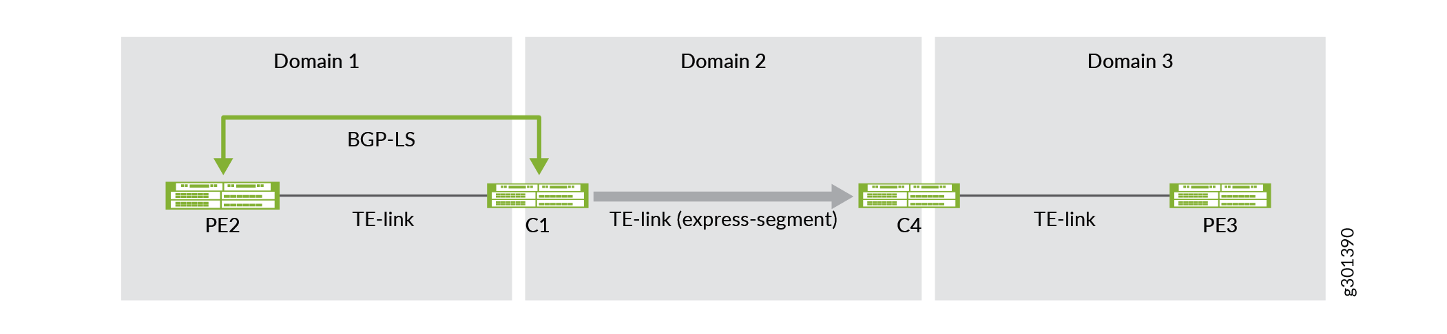
Express segments are a segment routing (SR) abstraction of an underlay path. Express segments facilitate the establishment of end-to-end SR paths using any underlay technology. The underlay technology currently supported are RSVP-TE and SR-TE. Express segment through RSVP-TE underlay is explained below.
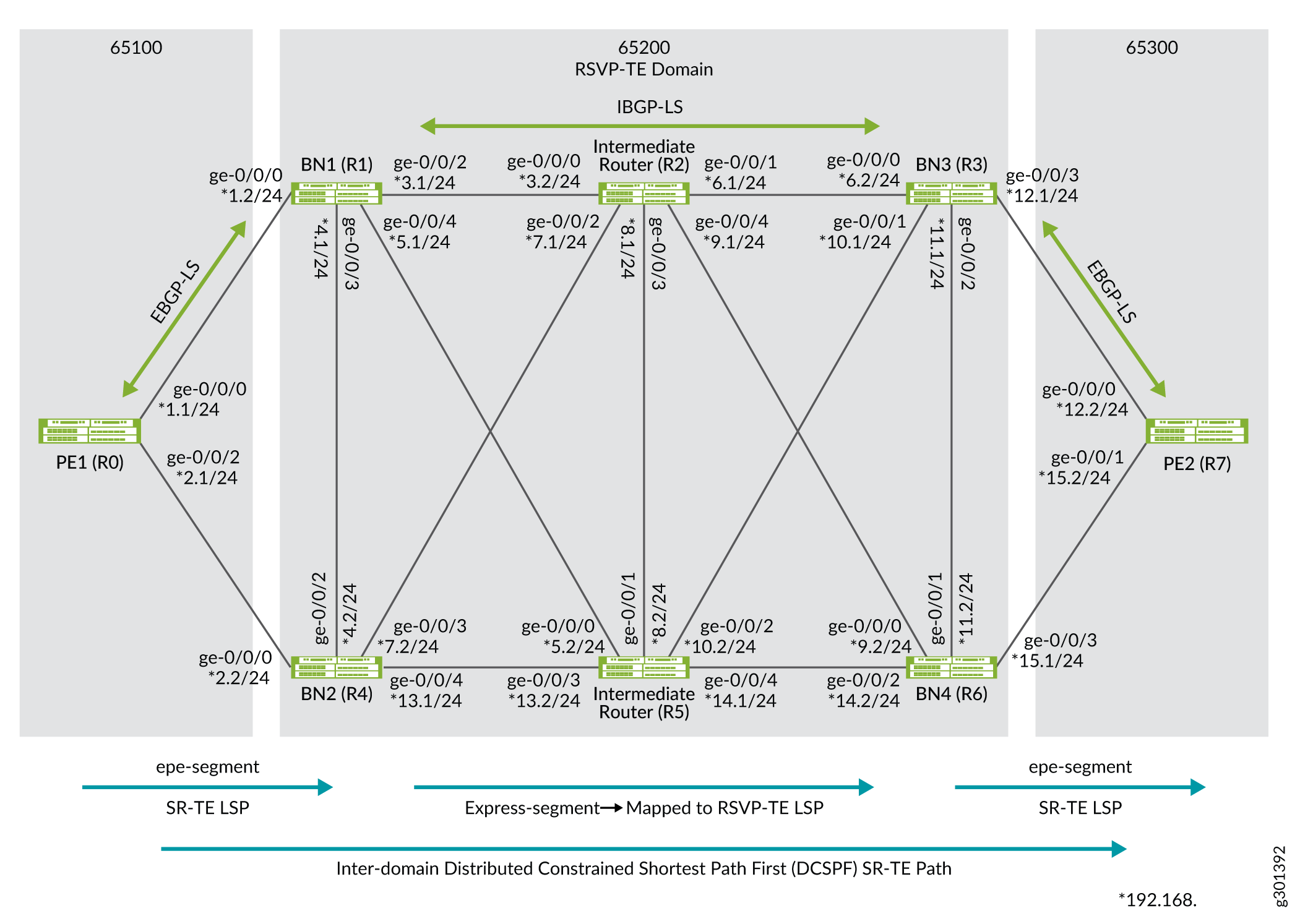
In Figure 1, Domain 2 leverages its RSVP-TE underlay LSPs for traffic engineering management and presents those underlay RSVP-TE LSPs as express segments to the adjacent domains (Domain 1 and Domain 3), therefore enabling end-to-end SR-TE path establishment.
Figure 1: Multi-Domain End-to-End SR-TE with RSVP Underlay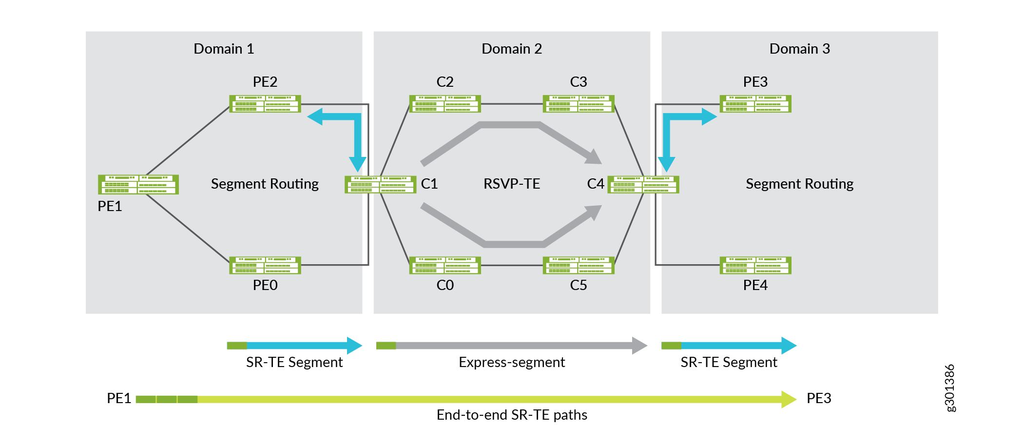
-
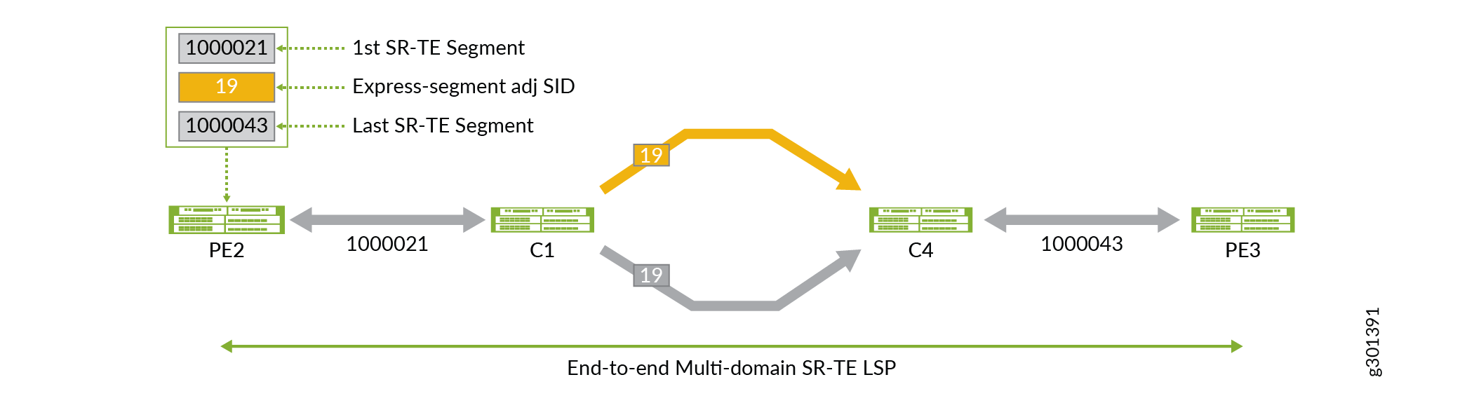
Express segments implicitly reduce the size of the SR segment list by compressing them (segment lists) to, at a minimum, one segment ID (SID)/label per domain. This becomes useful when end-to-end traffic engineered constraints would otherwise result in a segment list that exceeds the ingress router's label imposition capabilities. This also becomes beneficial when one or more domains are already implementing SR-TE for traffic engineered path management.
In Figure 2, you can see Domain 2 is using SR-TE and how the use of express segments enables PE1 device to use three labels to traverse the multi-domain network instead of five.
Figure 2: Multi-Domain End-to-End SR-TE with Reduced Label Stack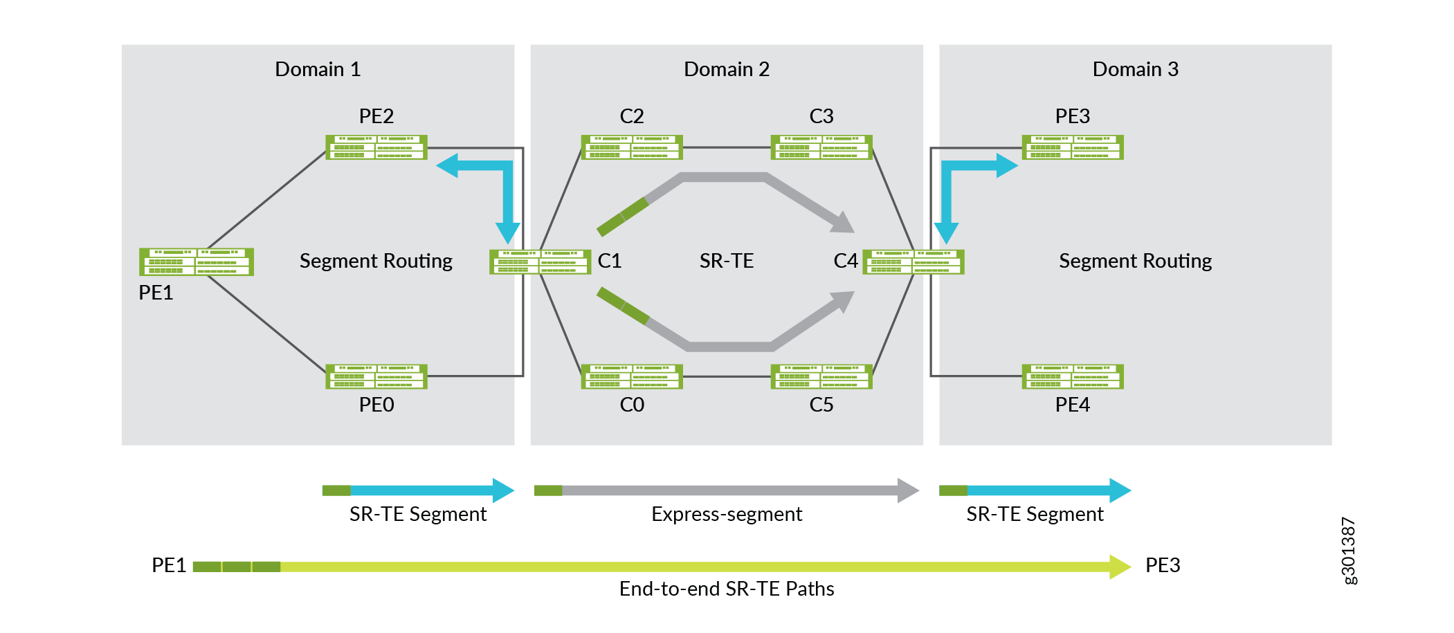
-
Express segments allow operators to present an abstraction of the network to adjacent domains and/or higher layer systems.
To establish a traffic engineered path through a series of interconnected domains or multi-domain network, it is necessary to have a certain amount of traffic engineering information about each network domain. Topology abstraction allows the use of policies to connect across domains. Topology abstraction does not necessarily offer all possible connectivity options but presents a view of potential connectivity according to the policies that determine how the domain resources need to be used. The domain could be constructed as a mesh of border node to border node express segments.
Using Figure 2, PE2’s view of an end-to-end traffic engineered system is represented in its local traffic engineering database as shown in Figure 3.
Figure 3: Abstracted Traffic Engineered Domain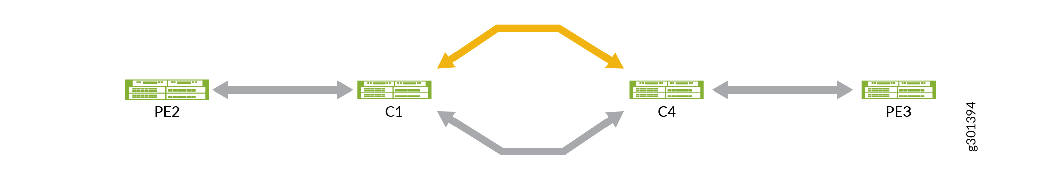
Use Cases
This section describes a few use cases for establishing end-to-end SR-TE connectivity. RFC7926 introduces a comprehensive set of terminology and use cases along with an architecture to facilitate traffic engineering link and node information exchange between domains. As Service providers' networks are expanding because of continued growth, multi-domain networks are becoming more prevalent. In these multi-domain networks, it is required to establish an end-to-end traffic engineered path between one or more domains from a source to a destination
Intra and Inter-domain SR-TE Connectivity Using Express Segments
Express segments have the capability to abstract traffic engineering information when the routing information exchange happens between domains. The traffic engineering information used as a criterion for path selection is the data relating to traffic engineered nodes and links. Traffic engineering information may be link metrics such as IGP, traffic engineering, latency, or administrative link attributes such as affinities. Express segments are best described as virtual traffic engineered Links that facilitate the abstraction of underlay LSPs.
Enhanced On-demand Next-hop
Enhanced On-demand Next-hop (EODN) (also known as BGP-triggered SR policies) facilitates the dynamic provisioning of end-to-end SR-TE policies, with constraints, upon the arrival of services routes. In large networks having hundreds of PE devices creating and maintaining traffic engineering policies on any ingress PE for every egress PE is challenging. Considering colors specific services (per VPN or per group of prefixes) makes things even more complicated and harder to maintain and troubleshoot. BGP triggered SR-TE addresses the task by automatically creating dynamic SR tunnels based on pre-configured templates. There is no need to provision ingress PEs with configuration for every egress PE.
How does Express Segment Work?
Express segments can be used to establish end-to-end traffic engineered paths between interconnected traffic engineered networks. Express segments (also known as virtual traffic engineering links) are generated dynamically through policies matching the underlay LSPs. Express segments and the corresponding abstracted topology (required by RFC7926) is generated with policies.
To apply a policy, include the policy policy-name
configuration statement at the [edit protocols express-segment
traffic-engineering] hierarchy level.
The policy-name is optional. If a policy name
is not defined, then the policy implicitly imports all the express segments into
the local traffic engineering database. An express segment template
automatically creates a one-on-one mapping of express links.
To configure express segment, include the express-segment
configuration statement under the [edit protocols] hierarchy
level.
Let us refer to Figure 1 and use the pair of RSVP-TE LSPs shown between C1 and C4 border nodes and how express segments are generated representing the underlay LSPs. In Figure 4, a policy is created to represent two RSVP-TE (gold and liquid-gold) LSPs as a single express segment.

The following is a sample policy where the policy name is matched through a regular expression and the end-point of the RSVP-TE LSPs:
protocols {
    express-segment-set gold-exp-seg {
        policy gold;
        }
    }
policy-options {
    policy-statement gold {
        from {
            route-filter 10/8 {
                install-next-hop lsp-regex *gold;
            }
        }
        then accept;
    }
}
In the following sample output, you can see the newly created express segment (Gold-Exp-Set-192.168.1.4) along with the traffic engineering attributes are inherited from the underlay RSVP-TE tunnels:
user@C1#show express-segments name gold-exp-seg-192.168.1.4 detail
Gold-Exp-Set-192.168.1.4
  To: 192.168.1.4, Set: gold-exp-set
  Status: Up (since 4d 11:09:05)
  Label: 19 (Route installed in mpls.0, TED entry added)
  LinkAttributes:
    ID: 2147483655
    TE-Metric: 10*, IGP-Metric: 30
    AdminGroups: gold, liquid-gold
    SRLGs: fiber-span-101
    BW: 1000Mbps
  UnderlayPaths:
    RSVP-LSP C1_to_C4_gold
      TE-Metric: 30, IGP-Metric: 30
      AdminGroups: gold
      SRLGs: fiber-span-101
      BW: 500Mbps
    RSVP-LSP C1_to_C4_liquid_gold
      TE-Metric: 30, IGP-Metric: 30
      AdminGroups: liquid-gold
      SRLGs: None
      BW: 500Mbps
You can observe the following in the output:
-
Automatic naming of the express segment (
Gold-Exp-Set-192.168.1.4). -
Traffic engineering attributes (bandwidth, metrics, admin groups, SRLGs) of the underlay RSVP-LSPs are inherited by the express segment.
-
The express segment is an unnumbered traffic engineered link and has been added to the traffic engineering database.
-
Label 19 has been assigned and installed in the
mpls.0forwarding table as the adjacency SID for the SR virtual traffic engineering link.
The following is an example where SR-TE LSP destination is matched:
protocols {
      express-segments {
        segment-set set1sr {
            membership-policy expresspolsr1;
        }
        traffic-engineering;
    }
policy-options {
    policy-statement expresspolsr1 {
        from {
            protocol spring-te;
            route-filter 3.3.3.3/32 exact;
        }
        then accept;
In the following sample output, you can see the newly created express segment (set1sr-3.3.3.3) from the uncolored SR-TE underlay tunnels:
user@C1show express-segments detail

Name: set1sr-3.3.3.3
  To: 3.3.3.3, Type: Dynamic (Set: set1sr)
  Label: 16 (Route installed in mpls.0, TED entry added)
  Status: Up (ElapsedTime: 5d 20:37:08)
  LinkAttributes:
    LocalID: 2147483649
    TE-Metric: 20, IGP-Metric: 20
    BW: 0bps
  UnderlayPaths: 1
    SRTE LSP: lsp1to3_sr
      TE-Metric: 0, IGP-Metric: 0
      BW: 0bps
How are Express Segments Advertised?
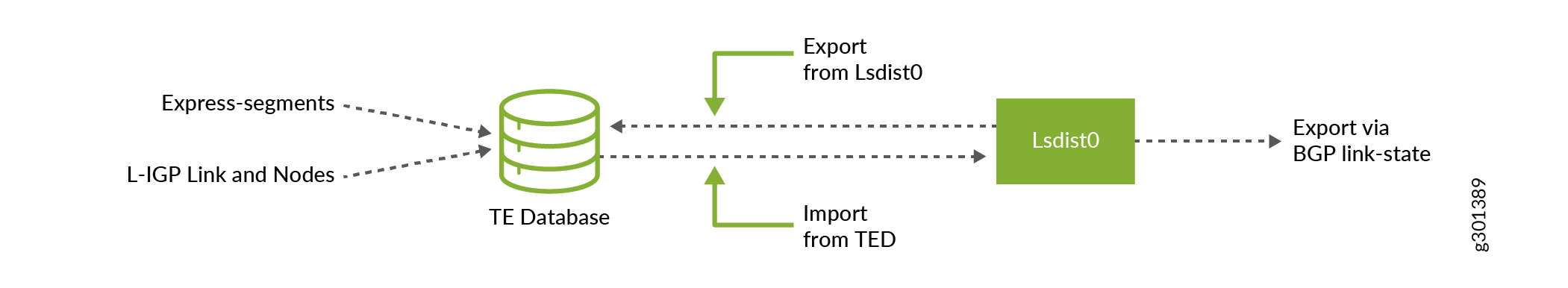
Express segments are advertised across domain boundaries or to higher-level controllers and Path Computing Elements (PCEs) using the BGP link state. When exchanging information through the BGP link state, the extensions for the BGP link state are used to advertise express segments as traffic engineered links. The express segment traffic engineered links and other normal traffic engineering links appear in the traffic engineering link-state database of any LSR in the network and are used for computing end-to-end traffic engineered paths. Express segment traffic engineering database entries are imported and exported from the lsdist.0 table for advertisement through the BGP link state with the following traffic-engineering database import and export configuration:
protocols {
    mpls {
        traffic-engineering {
            database {
                import {
                    l3-unicast-topology {
                        bgp-link-state;
                        }
                    policy es_2_bgpls;
                }
                export {
                    policy bgpls_2_ted;
                }
            }
        }
    }
    bgp {
        group te-peers {
            family traffic-engineering {
                unicast;
                }
            export abstract-topo;
        }
    }
}
Figure 5 provides a visual representation of how traffic engineering links and nodes are mirrored between the local traffic engineering database and the lsdist.0 RIB that BGP-LS uses for advertisement. As illustrated, there are several policy attachment points.
How are Express Segments Used by a Path Computing Element?
The BGP link state export policy is an effective place to create an abstract or customized topology that is advertised to a traffic engineered peer. For example, you may want to advertise only the express segment and Domain 3’s TE links and nodes to PE2 such that the traffic engineered topology is abstracted as shown in Figure 6. The abstracted view is then used by PE2 for end-to-end path computation.
The following is a sample configuration of a BGP link state export policy on C1:
policy-options {
    policy-statement abstract-topo {
        from {
            traffic-engineering {
                protocol express-segment;
                ipv4-prefix {
                    as 3;
                }
            }
        }
        then accept;
    }
}
The following is a sample SR policy configuration on PE2 router to establish an end-to-end multi-domain path from PE2 to PE3:
protocols {
    source-packet-routing {
        source-routing-path pe2-to-pe3 {
            to 192.168.70.1;
            color 10;
            primary {
                sl1 {
                    compute {
                        profile_any-path;
                    }
                }
            }
        }
    }
}
The resulting end-to-end path is represented in Figure 7. You can see the express segment’s adjacency SID (label 19) is used in the SR segment-list resulting in traffic being load-balanced over both the gold and liquid-gold RSVP-TE LSPs within Domain 2.
Example: Inter-domain SR-TE Connectivity Using Express Segments Through RSVP-TE Underlay
Use this example to learn how to establish an end-to-end inter-domain SR-TE connectivity using express segments.
Requirements
This example uses the following hardware and software components:
-
MX Series routers as provider edge, border nodes, and intermediate routers.
-
Junos OS Release 20.4R1 or later running on all devices.
Overview
The following topology (Figure 8) shows two SR-TE domains (AS100 and AS300) running EBGP-LS inter-connected through an RSVP-TE (AS200) domain:
Topology
In this topology, an end-to-end SR-TE path between PE1 router to PE2 router is established. Egress peer engineering (EPE) segments are defined on PE1 and PE2 routers to steer traffic towards their directly connected border nodes BN1/BN2 and BN3/BN4, respectively. EPE segments defined on the border nodes are advertised internally through the BGP link state. These two SR-TE domains are interconnected through the domain (AS200) that is leveraging RSVP-TE LSPs for internal path establishment.
The border nodes of the AS200 domain facilitate the abstraction of SR-TE information between domains. Express segments are created on border nodes (BN1, BN2, BN3, and BN4). Express segments are created in a one-on-one relationship with the underlying RSVP-TE LSPs and all express segments are inserted into the border node's local TE database for subsequent BGP link-state advertisement. The AS200 domain leverages RSVP-TE LSP underlays for TE management and presents those underlay RSVP-TE LSPs as express segments to the AS100 and the AS300 domains, enabling the domains to have end-to-end SR-TE LSP connectivity.
The following table describes the domains, routers, and connections in the topology:
|
Domain |
Devices |
Router ID/Lo) Address |
Connection Details |
|---|---|---|---|
|
AS65100 (EBGP-LS/ SR-TE LSP) |
R0(PE1 router) |
10.100.100.100 10.100.100.101 |
Connected to R1 (BN1 router) through interface ge-0/0/0, assigned IP address 192.168.1.1/24. Connected to R4 (BN2 router) through interface ge-0/0/2, assigned IP address 192.168.2.1/24. |
|
AS65200 (RSVP-TE LSP) |
R1(BN1 router) |
10.1.1.1 |
Connected to R0 (PE1 router) through interface ge-0/0/0, assigned IP address 192.168.1.2/24. Connected to R4 (BN2 router) through interface ge-0/0/3, assigned IP address 192.168.4.1/24. Connected to R2 (Intermediate router) through interface ge-0/0/2, assigned IP address 192.168.3.1/24. Connected to R5 (Intermediate router) through interface ge-0/0/4, assigned IP address 192.168.5.1/24. |
|
R4(BN2 router) |
10.4.4.4 |
Connected to R0 (PE1 router) through interface ge-0/0/0, assigned IP address 192.168.2.2/24. Connected to R1 (BN1 router) through interface ge-0/0/2, assigned IP address 192.168.4.2/24. Connected to R2 (Intermediate router) through interface ge-0/0/3, assigned IP address 192.168.7.1/24. Connected to R5 (Intermediate router) through interface ge-0/0/4, assigned IP address 192.168.13.1/24. |
|
|
R2(Intermediate router) |
10.2.2.2 |
Connected to R1 (BN1 router) through interface ge-0/0/0, assigned IP address 192.168.3.2/24. Connected to R4 (BN2 router) through interface ge-0/0/2, assigned IP address 192.168.7.1/24. Connected to R5 (Intermediate router) through interface ge-0/0/3, assigned IP address 192.168.8.1/24. Connected to R3 (BN3 router) through interface ge-0/0/1, assigned IP address 192.168.6.1/24. Connected to R6 (BN4 router) through interface ge-0/0/4, assigned IP address 192.168.9.1/24. |
|
|
R5(Intermediate router) |
10.5.5.5 |
Connected to R1 (BN1 router) through interface ge-0/0/0, assigned IP address 192.168.5.2/24. Connected to R4 (BN2 router) through interface ge-0/0/3, assigned IP address 192.168.13.2/24. Connected to R2 (Intermediate router) through interface ge-0/0/1, assigned IP address 192.168.8.2/24. Connected to R3 (BN3 router) through interface ge-0/0/2, assigned IP address 192.168.10.2/24. Connected to R6 (BN4 router) through interface ge-0/0/4, assigned IP address 192.168.14.1/24. |
|
|
R3(BN3 router) |
10.3.3.3 |
Connected to R7 (PE2 router) through interface ge-0/0/3, assigned IP address 192.168.12.1/24. Connected to R6 (BN4 router) through interface ge-0/0/2, assigned IP address 192.168.11.1/24. Connected to R2 (Intermediate router) through interface ge-0/0/0, assigned IP address 192.168.6.2/24. Connected to R5 (Intermediate router) through interface ge-0/0/1, assigned IP address 192.168.10.1/24. |
|
|
R6(BN4 router) |
10.6.6.6 |
Connected to R7 (PE2 router) through interface ge-0/0/3, assigned IP address 192.168.15.1/24. Connected to R3 (BN3 router) through interface ge-0/0/1, assigned IP address 192.168.11.2/24. Connected to R2 (Intermediate router) through interface ge-0/0/0, assigned IP address 192.168.9.2/24. Connected to R5 (Intermediate router) through interface ge-0/0/2, assigned IP address 192.168.14.2/24. |
|
|
AS65300(EBGP-LS/SR-TE LSP) |
R7(PE2 router) |
10.7.7.7 |
Connected to R3 (BN3 router) through interface ge-0/0/0, assigned IP address 192.168.12.2/24. Connected to R6 (BN4 router) through interface ge-0/0/1, assigned IP address 192.168.15.2/24. |
Configuration
To inter-connect a multi-domain network and establish an end-to-end SR path using express segments, perform these tasks:
- CLI Quick Configuration
- Configure R0 (PE1 router)
- Configure R1 (BN1 router)
- Configure R4 (BN2 router)
- Configure R2 (Intermediate router)
- Configure R5 (Intermediate router)
- Configure R3 (BN3 router)
- Configure R6 (BN4 router)
- Configure R7 (PE2 router)
CLI Quick Configuration
To quickly configure this example, copy the following commands, paste them into a
text file, remove any line breaks, change any details necessary to match your
network configuration, copy and paste the commands into the CLI at the
[edit] hierarchy level, and then enter
commit from configuration mode.
Device R0 (PE1 router)
set chassis network-services enhanced-ip
set interfaces ge-0/0/0 description To_R1_1
set interfaces ge-0/0/0 unit 0 family inet address 192.168.1.1/24
set interfaces ge-0/0/0 unit 0 family iso
set interfaces ge-0/0/0 unit 0 family mpls maximum-labels 8
set interfaces ge-0/0/2 description To_R4_1
set interfaces ge-0/0/2 unit 0 family inet address 192.168.2.1/24
set interfaces ge-0/0/2 unit 0 family iso
set interfaces ge-0/0/2 unit 0 family mpls maximum-labels 8
set interfaces lo0 unit 0 family inet address 10.100.100.100/32
set interfaces lo0 unit 0 family inet address 10.100.100.101/32
set interfaces lo0 unit 0 family iso address 49.0001.000a.0a0a.0a00
set policy-options policy-statement nlri2bgp_epe term 1 from family traffic-engineering
set policy-options policy-statement nlri2bgp_epe term 1 from protocol bgp-ls-epe
set policy-options policy-statement nlri2bgp_epe term 1 then next-hop self
set policy-options policy-statement nlri2bgp_epe term 1 then accept
set policy-options policy-statement nlri2ted_bgp term 1 from protocol bgp
set policy-options policy-statement nlri2ted_bgp term 1 then accept
set policy-options policy-statement pplb then load-balance per-packet
set policy-options policy-statement ted2nlri term 1 from protocol bgp-ls-epe
set policy-options policy-statement ted2nlri term 1 then accept
set routing-options static route 10.7.7.71/32 next-hop 10.7.7.7
set routing-options static route 10.7.7.71/32 resolve
set routing-options router-id 10.100.100.100
set routing-options autonomous-system 65100
set routing-options forwarding-table ecmp-fast-reroute
set protocols bgp group ebgp1 type external
set protocols bgp group ebgp1 family inet unicast
set protocols bgp group ebgp1 family traffic-engineering unicast
set protocols bgp group ebgp1 export nlri2bgp_epe
set protocols bgp group ebgp1 neighbor 192.168.1.2 peer-as 65200
set protocols bgp group ebgp1 neighbor 192.168.1.2 egress-te-adj-segment epe_adj1_toR1 label 7101
set protocols bgp group ebgp1 neighbor 192.168.1.2 egress-te-adj-segment epe_adj1_toR1 next-hop 192.168.1.2
set protocols bgp group ebgp1 neighbor 192.168.1.2 egress-te-adj-segment epe_adj1_toR1 te-link-attribute te-metric 20
set protocols bgp group ebgp1 neighbor 192.168.1.2 egress-te-adj-segment epe_adj1_toR1 te-link-attribute igp-metric 10
set protocols bgp group ebgp1 neighbor 192.168.1.2 egress-te-adj-segment epe_adj1_toR1 te-link-attribute admin-group red
set protocols bgp group ebgp1 neighbor 192.168.1.2 egress-te-adj-segment epe_adj1_toR1 te-link-attribute admin-group brown
set protocols bgp group ebgp1 neighbor 192.168.2.2 peer-as 200
set protocols bgp group ebgp1 neighbor 192.168.2.2 egress-te-adj-segment epe_adj1_toR4 label 7104
set protocols bgp group ebgp1 neighbor 192.168.2.2 egress-te-adj-segment epe_adj1_toR4 next-hop 192.168.2.2
set protocols bgp group ebgp1 neighbor 192.168.2.2 egress-te-adj-segment epe_adj1_toR4 te-link-attribute te-metric 20
set protocols bgp group ebgp1 neighbor 192.168.2.2 egress-te-adj-segment epe_adj1_toR4 te-link-attribute igp-metric 10
set protocols bgp group ebgp1 neighbor 192.168.2.2 egress-te-adj-segment epe_adj1_toR4 te-link-attribute admin-group red
set protocols bgp group ebgp1 neighbor 192.168.2.2 egress-te-adj-segment epe_adj1_toR4 te-link-attribute admin-group brown
set protocols mpls traffic-engineering database import l3-unicast-topology bgp-link-state
set protocols mpls traffic-engineering database import policy ted2nlri
set protocols mpls traffic-engineering database export policy nlri2ted_bgp
set protocols mpls traffic-engineering database export l3-unicast-topology
set protocols mpls admin-groups red 0
set protocols mpls admin-groups blue 1
set protocols mpls admin-groups brown 5
set protocols mpls label-range static-label-range 7000 70000
set protocols mpls interface all
set protocols source-packet-routing compute-profile compute1 no-label-stack-compression
set protocols source-packet-routing compute-profile ecompute1 admin-group include-any red
set protocols source-packet-routing compute-profile ecompute1 admin-group include-any brown
set protocols source-packet-routing compute-profile ecompute1 no-label-stack-compression
set protocols source-packet-routing compute-profile ecompute2 admin-group include-any red
set protocols source-packet-routing compute-profile ecompute2 admin-group include-any blue
set protocols source-packet-routing compute-profile ecompute2 no-label-stack-compression
set protocols source-packet-routing source-routing-path computelsp1 to 10.7.7.7
set protocols source-packet-routing source-routing-path computelsp1 install 10.7.7.71
set protocols source-packet-routing source-routing-path computelsp1 primary p1 compute compute1
set protocols source-packet-routing source-routing-path ecomputelsp1 to 10.7.7.7
set protocols source-packet-routing source-routing-path ecomputelsp1 color 7000
set protocols source-packet-routing source-routing-path ecomputelsp1 primary p1 compute ecompute1
set protocols source-packet-routing source-routing-path ecomputelsp2 to 10.7.7.7
set protocols source-packet-routing source-routing-path ecomputelsp2 color 7001
set protocols source-packet-routing source-routing-path ecomputelsp2 primary p1 compute ecompute2
Device R1 (BN1 router)
set chassis network-services enhanced-ip
set interfaces ge-0/0/0 description To_R0_1
set interfaces ge-0/0/0 unit 0 family inet address 192.168.1.2/24
set interfaces ge-0/0/0 unit 0 family iso
set interfaces ge-0/0/0 unit 0 family mpls maximum-labels 8
set interfaces ge-0/0/2 description To_R2
set interfaces ge-0/0/2 unit 0 family inet address 192.168.3.1/24
set interfaces ge-0/0/2 unit 0 family iso
set interfaces ge-0/0/2 unit 0 family mpls maximum-labels 8
set interfaces ge-0/0/3 description to-R4
set interfaces ge-0/0/3 unit 0 family inet address 192.168.4.1/24
set interfaces ge-0/0/3 unit 0 family iso
set interfaces ge-0/0/3 unit 0 family mpls maximum-labels 8
set interfaces ge-0/0/4 description to-R5
set interfaces ge-0/0/4 unit 0 family inet address 192.168.5.1/24
set interfaces ge-0/0/4 unit 0 family iso
set interfaces ge-0/0/4 unit 0 family mpls maximum-labels 8
set interfaces lo0 unit 0 family inet address 10.1.1.1/32
set interfaces lo0 unit 0 family iso address 49.0001.0001.0101.0100
set policy-options policy-statement expresspol1 from route-filter 10.6.6.6/32 exact install-nexthop lsp lsp1to6_a
set policy-options policy-statement expresspol1 then accept
set policy-options policy-statement expresspol2 from route-filter 10.3.3.3/32 exact install-nexthop lsp lsp1to3_a
set policy-options policy-statement expresspol2 then accept
set policy-options policy-statement nlri2bgp_epe term 1 from family traffic-engineering
set policy-options policy-statement nlri2bgp_epe term 1 from protocol bgp-ls-epe
set policy-options policy-statement nlri2bgp_epe term 1 then next-hop self
set policy-options policy-statement nlri2bgp_epe term 1 then accept
set policy-options policy-statement nlri2bgp_stat term 1 from family traffic-engineering
set policy-options policy-statement nlri2bgp_stat term 1 from protocol express-segments
set policy-options policy-statement nlri2bgp_stat term 1 then accept
set policy-options policy-statement pplb then load-balance per-packet
set policy-options policy-statement ted2nlri_epe_stat term 1 from family traffic-engineering
set policy-options policy-statement ted2nlri_epe_stat term 1 from protocol express-segments
set policy-options policy-statement ted2nlri_epe_stat term 1 then accept
set policy-options policy-statement ted2nlri_epe_stat term 2 from family traffic-engineering
set policy-options policy-statement ted2nlri_epe_stat term 2 from protocol bgp-ls-epe
set policy-options policy-statement ted2nlri_epe_stat term 2 then accept
set policy-options policy-statement ted2nlri_epe_stat term 3 from protocol isis
set policy-options policy-statement ted2nlri_epe_stat term 3 then reject
set routing-options router-id 10.1.1.1
set routing-options autonomous-system 65200
set protocols bgp group ebgp1 type external
set protocols bgp group ebgp1 family inet-vpn unicast
set protocols bgp group ebgp1 family traffic-engineering unicast
set protocols bgp group ebgp1 export nlri2bgp_stat
set protocols bgp group ebgp1 neighbor 192.168.1.1 peer-as 65100
set protocols bgp group ebgp1 neighbor 192.168.1.1 egress-te-adj-segment epe_adj1_toR0 label 8110
set protocols bgp group ebgp1 neighbor 192.168.1.1 egress-te-adj-segment epe_adj1_toR0 next-hop 192.168.1.1
set protocols bgp group ebgp1 neighbor 192.168.1.1 egress-te-adj-segment epe_adj1_toR0 te-link-attribute te-metric 20
set protocols bgp group ebgp1 neighbor 192.168.1.1 egress-te-adj-segment epe_adj1_toR0 te-link-attribute igp-metric 10
set protocols bgp group ebgp1 neighbor 192.168.1.1 egress-te-adj-segment epe_adj1_toR0 te-link-attribute admin-group red
set protocols bgp group ebgp1 neighbor 192.168.1.1 egress-te-adj-segment epe_adj1_toR0 te-link-attribute admin-group brown
set protocols bgp group ibgp1 type internal
set protocols bgp group ibgp1 local-address 10.1.1.1
set protocols bgp group ibgp1 family traffic-engineering unicast
set protocols bgp group ibgp1 export nlri2bgp_epe
set protocols bgp group ibgp1 neighbor 10.2.2.2
set protocols bgp group ibgp1 neighbor 10.5.5.5
set protocols express-segments segment-template template1 admin-group red
set protocols express-segments segment-template template1 metric te 200
set protocols express-segments segment-template template1 metric igp 100
set protocols express-segments segment-set r1-exp-set1 membership-policy expresspol1
set protocols express-segments segment-set r1-exp-set1 template template1
set protocols express-segments segment-set r1-exp-set2 membership-policy expresspol2
set protocols express-segments traffic-engineering
set protocols isis interface ge-0/0/2.0
set protocols isis interface ge-0/0/3.0
set protocols isis interface ge-0/0/4.0
set protocols isis interface lo0.0 passive
set protocols isis level 1 disable
set protocols isis level 2 wide-metrics-only
set protocols mpls traffic-engineering database import l3-unicast-topology bgp-link-state
set protocols mpls traffic-engineering database import policy ted2nlri_epe_stat
set protocols mpls traffic-engineering database export l3-unicast-topology
set protocols mpls admin-groups red 0
set protocols mpls admin-groups blue 1
set protocols mpls admin-groups brown 5
set protocols mpls label-switched-path lsp1to6_a to 10.6.6.6
set protocols mpls label-switched-path lsp1to6_a admin-group include-any brown
set protocols mpls label-switched-path lsp1to6_a admin-group include-any red
set protocols mpls label-switched-path lsp1to6_b to 10.6.6.6
set protocols mpls label-switched-path lsp1to6_b admin-group include-any brown
set protocols mpls label-switched-path lsp1to6_b admin-group include-any blue
set protocols mpls label-switched-path lsp1to6_c to 10.6.6.6
set protocols mpls label-switched-path lsp1to6_c admin-group include-any blue
set protocols mpls label-switched-path lsp1to3_a to 10.3.3.3
set protocols mpls label-switched-path lsp1to3_a admin-group include-any brown
set protocols mpls label-switched-path lsp1to3_a admin-group include-any red
set protocols mpls label-switched-path lsp1to3_b to 10.3.3.3
set protocols mpls label-switched-path lsp1to3_b admin-group include-any blue
set protocols mpls label-range static-label-range 7000 70000
set protocols mpls interface ge-0/0/3.0 admin-group red
set protocols mpls interface ge-0/0/2.0 admin-group brown
set protocols mpls interface ge-0/0/4.0 admin-group blue
set protocols mpls interface all
set protocols rsvp interface all link-protection
Device R4 (BN2 router)
set chassis network-services enhanced-ip
set interfaces ge-0/0/0 description To_R0
set interfaces ge-0/0/0 unit 0 family inet address 192.168.2.2/24
set interfaces ge-0/0/0 unit 0 family iso
set interfaces ge-0/0/0 unit 0 family mpls maximum-labels 8
set interfaces ge-0/0/2 description To_R1
set interfaces ge-0/0/2 unit 0 family inet address 192.168.4.2/24
set interfaces ge-0/0/2 unit 0 family iso
set interfaces ge-0/0/2 unit 0 family mpls maximum-labels 8
set interfaces ge-0/0/3 description To_R2
set interfaces ge-0/0/3 unit 0 family inet address 192.168.7.2/24
set interfaces ge-0/0/3 unit 0 family iso
set interfaces ge-0/0/3 unit 0 family mpls maximum-labels 8
set interfaces ge-0/0/4 description To_R5
set interfaces ge-0/0/4 unit 0 family inet address 192.168.13.1/24
set interfaces ge-0/0/4 unit 0 family iso
set interfaces ge-0/0/4 unit 0 family mpls maximum-labels 8
set interfaces lo0 unit 0 family inet address 10.4.4.4/32
set interfaces lo0 unit 0 family iso address 49.0001.0004.0404.0400
set policy-options policy-statement expresspol1 from route-filter 10.6.6.6/32 exact install-nexthop lsp lsp4to6_a
set policy-options policy-statement expresspol1 then accept
set policy-options policy-statement expresspol2 from route-filter 10.3.3.3/32 exact install-nexthop lsp lsp4to3_a
set policy-options policy-statement expresspol2 then accept
set policy-options policy-statement nlri2bgp_epe term 1 from family traffic-engineering
set policy-options policy-statement nlri2bgp_epe term 1 from protocol bgp-ls-epe
set policy-options policy-statement nlri2bgp_epe term 1 then next-hop self
set policy-options policy-statement nlri2bgp_epe term 1 then accept
set policy-options policy-statement nlri2bgp_stat term 1 from family traffic-engineering
set policy-options policy-statement nlri2bgp_stat term 1 from protocol express-segments
set policy-options policy-statement nlri2bgp_stat term 1 then accept
set policy-options policy-statement pplb then load-balance per-packet
set policy-options policy-statement ted2nlri_epe_stat term 1 from family traffic-engineering
set policy-options policy-statement ted2nlri_epe_stat term 1 from protocol express-segments
set policy-options policy-statement ted2nlri_epe_stat term 1 then accept
set policy-options policy-statement ted2nlri_epe_stat term 2 from family traffic-engineering
set policy-options policy-statement ted2nlri_epe_stat term 2 from protocol bgp-ls-epe
set policy-options policy-statement ted2nlri_epe_stat term 2 then accept
set policy-options policy-statement ted2nlri_epe_stat term 3 from protocol isis
set policy-options policy-statement ted2nlri_epe_stat term 3 then reject
set routing-options router-id 10.4.4.4
set routing-options autonomous-system 65200
set protocols bgp group ibgp1 type internal
set protocols bgp group ibgp1 local-address 10.4.4.4
set protocols bgp group ibgp1 family traffic-engineering unicast
set protocols bgp group ibgp1 export nlri2bgp_epe
set protocols bgp group ibgp1 neighbor 10.2.2.2
set protocols bgp group ibgp1 neighbor 10.5.5.5
set protocols bgp group ebgp1 type external
set protocols bgp group ebgp1 family inet-vpn unicast
set protocols bgp group ebgp1 family traffic-engineering unicast
set protocols bgp group ebgp1 export nlri2bgp_stat
set protocols bgp group ebgp1 neighbor 192.168.2.1 peer-as 65100
set protocols bgp group ebgp1 neighbor 192.168.2.1 egress-te-adj-segment epe_adj1_toR0 label 8140
set protocols bgp group ebgp1 neighbor 192.168.2.1 egress-te-adj-segment epe_adj1_toR0 next-hop 192.168.2.1
set protocols bgp group ebgp1 neighbor 192.168.2.1 egress-te-adj-segment epe_adj1_toR0 te-link-attribute te-metric 20
set protocols bgp group ebgp1 neighbor 192.168.2.1 egress-te-adj-segment epe_adj1_toR0 te-link-attribute igp-metric 10
set protocols bgp group ebgp1 neighbor 192.168.2.1 egress-te-adj-segment epe_adj1_toR0 te-link-attribute admin-group red
set protocols bgp group ebgp1 neighbor 192.168.2.1 egress-te-adj-segment epe_adj1_toR0 te-link-attribute admin-group brown
set protocols express-segments segment-set r4-exp-set1 membership-policy expresspol1
set protocols express-segments segment-set r4-exp-set2 membership-policy expresspol2
set protocols express-segments traffic-engineering
set protocols isis interface ge-0/0/0.0
set protocols isis interface ge-0/0/2.0
set protocols isis interface ge-0/0/3.0
set protocols isis interface ge-0/0/4.0
set protocols isis interface lo0.0 passive
set protocols isis level 1 disable
set protocols isis level 2 wide-metrics-only
set protocols mpls traffic-engineering database import l3-unicast-topology bgp-link-state
set protocols mpls traffic-engineering database import policy ted2nlri_epe_stat
set protocols mpls traffic-engineering database export l3-unicast-topology
set protocols mpls admin-groups red 0
set protocols mpls admin-groups blue 1
set protocols mpls admin-groups brown 5
set protocols mpls label-switched-path lsp4to6_a to 10.6.6.6
set protocols mpls label-switched-path lsp4to6_a admin-group include-any brown
set protocols mpls label-switched-path lsp4to6_a admin-group include-any red
set protocols mpls label-switched-path lsp4to6_b to 10.6.6.6
set protocols mpls label-switched-path lsp4to6_b admin-group include-any blue
set protocols mpls label-switched-path lsp4to3_a to 10.3.3.3
set protocols mpls label-switched-path lsp4to3_a admin-group include-any brown
set protocols mpls label-switched-path lsp4to3_a admin-group include-any red
set protocols mpls label-switched-path lsp4to3_b to 10.3.3.3
set protocols mpls label-switched-path lsp4to3_b admin-group include-any brown
set protocols mpls label-switched-path lsp4to3_c to 10.3.3.3
set protocols mpls label-switched-path lsp4to3_c admin-group include-any brown
set protocols mpls label-range static-label-range 7000 70000
set protocols mpls interface ge-0/0/2.0 admin-group red
set protocols mpls interface ge-0/0/4.0 admin-group brown
set protocols mpls interface all
set protocols rsvp interface all link-protection
Device R2 (Intermediate router)
set chassis network-services enhanced-ip
set interfaces ge-0/0/0 description To_R1
set interfaces ge-0/0/0 unit 0 family inet address 192.168.3.2/24
set interfaces ge-0/0/0 unit 0 family iso
set interfaces ge-0/0/0 unit 0 family mpls maximum-labels 8
set interfaces ge-0/0/1 description To_R3
set interfaces ge-0/0/1 unit 0 family inet address 192.168.6.1/24
set interfaces ge-0/0/1 unit 0 family iso
set interfaces ge-0/0/1 unit 0 family mpls maximum-labels 8
set interfaces ge-0/0/2 description To_R4
set interfaces ge-0/0/2 unit 0 family inet address 192.168.7.1/24
set interfaces ge-0/0/2 unit 0 family iso
set interfaces ge-0/0/2 unit 0 family mpls maximum-labels 8
set interfaces ge-0/0/3 description To_R5
set interfaces ge-0/0/3 unit 0 family inet address 192.168.8.1/24
set interfaces ge-0/0/3 unit 0 family iso
set interfaces ge-0/0/3 unit 0 family mpls maximum-labels 8
set interfaces ge-0/0/4 description To_R6
set interfaces ge-0/0/4 unit 0 family inet address 192.168.9.1/24
set interfaces ge-0/0/4 unit 0 family iso
set interfaces ge-0/0/4 unit 0 family mpls maximum-labels 8
set interfaces lo0 unit 0 family inet address 10.2.2.2/32
set interfaces lo0 unit 0 family iso address 49.0001.0002.0202.0200
set policy-options policy-statement bgplsepe_rt_2_ted term 1 from protocol bgp
set policy-options policy-statement bgplsepe_rt_2_ted term 1 then accept
set policy-options policy-statement nlri2bgp term 1 from family traffic-engineering
set policy-options policy-statement nlri2bgp term 1 then next-hop self
set policy-options policy-statement nlri2bgp term 1 then accept
set policy-options policy-statement nlri2bgp_igp term 1 from family traffic-engineering
set policy-options policy-statement nlri2bgp_igp term 1 from protocol isis
set policy-options policy-statement nlri2bgp_igp term 1 then accept
set policy-options policy-statement nlri2ted_igp term 1 from traffic-engineering protocol isis-level-2
set policy-options policy-statement nlri2ted_igp term 1 then accept
set policy-options policy-statement pplb then load-balance per-packet
set policy-options policy-statement ted2nlri term 1 from protocol bgp-ls-epe
set policy-options policy-statement ted2nlri term 1 then accept
set policy-options policy-statement ted2nlri_1 term 1 from traffic-engineering
set policy-options policy-statement ted2nlri_1 term 1 then accept
set policy-options policy-statement ted2nlri_igp term 1 from family traffic-engineering
set policy-options policy-statement ted2nlri_igp term 1 from protocol isis
set policy-options policy-statement ted2nlri_igp term 1 then accept
set routing-options router-id 10.2.2.2
set routing-options autonomous-system 65200
set protocols bgp group RR1 type internal
set protocols bgp group RR1 local-address 10.2.2.2
set protocols bgp group RR1 family traffic-engineering unicast
set protocols bgp group RR1 neighbor 10.1.1.1
set protocols bgp group RR1 neighbor 10.3.3.3
set protocols bgp group RR1 neighbor 10.6.6.6
set protocols bgp group RR1 neighbor 10.4.4.4
set protocols bgp cluster 10.2.2.2
set protocols isis interface ge-0/0/0.0
set protocols isis interface ge-0/0/1.0
set protocols isis interface ge-0/0/2.0
set protocols isis interface ge-0/0/3.0
set protocols isis interface ge-0/0/4.0
set protocols isis interface lo0.0 passive
set protocols isis level 1 disable
set protocols isis level 2 wide-metrics-only
set protocols mpls admin-groups red 0
set protocols mpls admin-groups blue 1
set protocols mpls admin-groups brown 5
set protocols mpls label-range static-label-range 7000 70000
set protocols mpls interface ge-0/0/0.0 admin-group brown
set protocols mpls interface ge-0/0/3.0 admin-group red
set protocols mpls interface ge-0/0/4.0 admin-group blue
set protocols mpls interface ge-0/0/1.0 admin-group brown
set protocols mpls interface all
set protocols rsvp interface all link-protection
Device R5 (Intermediate router)
set chassis network-services enhanced-ip
set interfaces ge-0/0/0 description To_R1
set interfaces ge-0/0/0 unit 0 family inet address 192.168.5.2/24
set interfaces ge-0/0/0 unit 0 family iso
set interfaces ge-0/0/0 unit 0 family mpls maximum-labels 8
set interfaces ge-0/0/1 description To_R2
set interfaces ge-0/0/1 unit 0 family inet address 192.168.8.2/24
set interfaces ge-0/0/1 unit 0 family iso
set interfaces ge-0/0/1 unit 0 family mpls maximum-labels 8
set interfaces ge-0/0/2 description To_R3
set interfaces ge-0/0/2 unit 0 family inet address 192.168.10.2/24
set interfaces ge-0/0/2 unit 0 family iso
set interfaces ge-0/0/2 unit 0 family mpls maximum-labels 8
set interfaces ge-0/0/3 description To_R4
set interfaces ge-0/0/3 unit 0 family inet address 192.168.13.2/24
set interfaces ge-0/0/3 unit 0 family iso
set interfaces ge-0/0/3 unit 0 family mpls maximum-labels 8
set interfaces ge-0/0/4 description To_R6
set interfaces ge-0/0/4 unit 0 family inet address 192.168.14.1/24
set interfaces ge-0/0/4 unit 0 family iso
set interfaces ge-0/0/4 unit 0 family mpls maximum-labels 8
set interfaces lo0 unit 0 family inet address 10.5.5.5/32
set interfaces lo0 unit 0 family iso address 49.0001.0005.0505.0500
set policy-options policy-statement nlri2bgp term 1 from family traffic-engineering
set policy-options policy-statement nlri2bgp term 1 then next-hop self
set policy-options policy-statement nlri2bgp term 1 then accept
set policy-options policy-statement nlri2ted_igp term 1 from traffic-engineering protocol isis-level-2
set policy-options policy-statement nlri2ted_igp term 1 then accept
set policy-options policy-statement pplb then load-balance per-packet
set policy-options policy-statement ted2nlri term 1 from protocol bgp-ls-epe
set policy-options policy-statement ted2nlri term 1 then accept
set policy-options policy-statement ted2nlri_igp term 1 from family traffic-engineering
set policy-options policy-statement ted2nlri_igp term 1 from protocol isis
set policy-options policy-statement ted2nlri_igp term 1 then accept
set routing-options router-id 10.5.5.5
set routing-options autonomous-system 65200
set protocols bgp group RR2 type internal
set protocols bgp group RR2 family inet unicast
set protocols bgp group RR2 family traffic-engineering unicast
set protocols bgp group RR2 neighbor 10.1.1.1
set protocols bgp group RR2 neighbor 10.3.3.3
set protocols bgp group RR2 neighbor 10.6.6.6
set protocols bgp group RR2 neighbor 10.4.4.4
set protocols bgp cluster 10.5.5.5
set protocols isis interface ge-0/0/0.0
set protocols isis interface ge-0/0/1.0
set protocols isis interface ge-0/0/2.0
set protocols isis interface ge-0/0/3.0
set protocols isis interface ge-0/0/4.0
set protocols isis interface lo0.0 passive
set protocols isis level 1 disable
set protocols isis level 2 wide-metrics-only
set protocols mpls admin-groups red 0
set protocols mpls admin-groups blue 1
set protocols mpls admin-groups brown 5
set protocols mpls label-range static-label-range 7000 70000
set protocols mpls interface ge-0/0/0.0 admin-group blue
set protocols mpls interface ge-0/0/1.0 admin-group red
set protocols mpls interface ge-0/0/3.0 admin-group brown
set protocols mpls interface ge-0/0/4.0 admin-group brown
set protocols mpls interface all
set protocols rsvp interface all link-protection
Device R3 (BN3 router)
set chassis network-services enhanced-ip
set interfaces ge-0/0/0 description To_R2
set interfaces ge-0/0/0 unit 0 family inet address 192.168.6.2/24
set interfaces ge-0/0/0 unit 0 family iso
set interfaces ge-0/0/0 unit 0 family mpls maximum-labels 8
set interfaces ge-0/0/1 description To_R5
set interfaces ge-0/0/1 unit 0 family inet address 192.168.10.1/24
set interfaces ge-0/0/1 unit 0 family iso
set interfaces ge-0/0/1 unit 0 family mpls maximum-labels 8
set interfaces ge-0/0/2 description To_R6
set interfaces ge-0/0/2 unit 0 family inet address 192.168.11.1/24
set interfaces ge-0/0/2 unit 0 family iso
set interfaces ge-0/0/2 unit 0 family mpls maximum-labels 8
set interfaces ge-0/0/3 description To_R7
set interfaces ge-0/0/3 unit 0 family inet address 192.168.12.1/24
set interfaces ge-0/0/3 unit 0 family iso
set interfaces ge-0/0/3 unit 0 family mpls maximum-labels 8
set interfaces lo0 unit 0 family inet address 10.3.3.3/32
set interfaces lo0 unit 0 family iso address 49.0001.0003.0303.0300
set policy-options policy-statement expresspol1 from route-filter 10.1.1.1/32 exact install-nexthop lsp lsp3to1_a
set policy-options policy-statement expresspol1 then accept
set policy-options policy-statement expresspol2 from route-filter 10.4.4.4/32 exact install-nexthop lsp lsp3to4_a
set policy-options policy-statement expresspol2 then accept
set policy-options policy-statement nlri2bgp_epe term 1 from family traffic-engineering
set policy-options policy-statement nlri2bgp_epe term 1 from protocol bgp-ls-epe
set policy-options policy-statement nlri2bgp_epe term 1 then next-hop self
set policy-options policy-statement nlri2bgp_epe term 1 then accept
set policy-options policy-statement nlri2bgp_stat term 1 from family traffic-engineering
set policy-options policy-statement nlri2bgp_stat term 1 from protocol express-segments
set policy-options policy-statement nlri2bgp_stat term 1 then accept
set policy-options policy-statement pplb then load-balance per-packet
set policy-options policy-statement ted2nlri_epe_stat term 1 from family traffic-engineering
set policy-options policy-statement ted2nlri_epe_stat term 1 from protocol static
set policy-options policy-statement ted2nlri_epe_stat term 1 then accept
set policy-options policy-statement ted2nlri_epe_stat term 2 from family traffic-engineering
set policy-options policy-statement ted2nlri_epe_stat term 2 from protocol bgp-ls-epe
set policy-options policy-statement ted2nlri_epe_stat term 2 then accept
set policy-options policy-statement ted2nlri_epe_stat term 3 from protocol isis
set policy-options policy-statement ted2nlri_epe_stat term 3 then reject
set routing-options router-id 10.3.3.3
set routing-options autonomous-system 65200
set protocols bgp group ibgp1 type internal
set protocols bgp group ibgp1 local-address 10.3.3.3
set protocols bgp group ibgp1 family traffic-engineering unicast
set protocols bgp group ibgp1 export nlri2bgp_epe
set protocols bgp group ibgp1 neighbor 10.2.2.2
set protocols bgp group ibgp1 neighbor 10.5.5.5
set protocols bgp group ebgp1 type external
set protocols bgp group ebgp1 family traffic-engineering unicast
set protocols bgp group ebgp1 export nlri2bgp_stat
set protocols bgp group ebgp1 neighbor 192.168.12.2 peer-as 65300
set protocols bgp group ebgp1 neighbor 192.168.12.2 egress-te-adj-segment epe_adj1_toR7 label 7137
set protocols bgp group ebgp1 neighbor 192.168.12.2 egress-te-adj-segment epe_adj1_toR7 next-hop 192.168.12.2
set protocols bgp group ebgp1 neighbor 192.168.12.2 egress-te-adj-segment epe_adj1_toR7 te-link-attribute te-metric 20
set protocols bgp group ebgp1 neighbor 192.168.12.2 egress-te-adj-segment epe_adj1_toR7 te-link-attribute igp-metric 10
set protocols bgp group ebgp1 neighbor 192.168.12.2 egress-te-adj-segment epe_adj1_toR7 te-link-attribute admin-group red
set protocols bgp group ebgp1 neighbor 192.168.12.2 egress-te-adj-segment epe_adj1_toR7 te-link-attribute admin-group brown
set protocols bgp group ebgp1 vpn-apply-export
set protocols express-segments segment-set set1 membership-policy expresspol1
set protocols express-segments segment-set set2 membership-policy expresspol2
set protocols express-segments traffic-engineering
set protocols isis interface ge-0/0/0.0
set protocols isis interface ge-0/0/1.0
set protocols isis interface ge-0/0/2.0
set protocols isis interface ge-0/0/3.0 passive
set protocols isis interface lo0.0 passive
set protocols isis level 1 disable
set protocols isis level 2 wide-metrics-only
set protocols mpls traffic-engineering database import l3-unicast-topology bgp-link-state
set protocols mpls traffic-engineering database import policy ted2nlri_epe_stat
set protocols mpls traffic-engineering database export l3-unicast-topology
set protocols mpls admin-groups red 0
set protocols mpls admin-groups blue 1
set protocols mpls admin-groups brown 5
set protocols mpls label-switched-path lsp3to1_a to 10.1.1.1
set protocols mpls label-switched-path lsp3to1_a admin-group include-any red
set protocols mpls label-switched-path lsp3to1_a admin-group include-any brown
set protocols mpls label-switched-path lsp3to4_a to 10.4.4.4
set protocols mpls label-switched-path lsp3to4_a admin-group include-any red
set protocols mpls label-switched-path lsp3to4_a admin-group include-any brown
set protocols mpls label-range static-label-range 7000 70000
set protocols mpls interface ge-0/0/0.0 admin-group brown
set protocols mpls interface ge-0/0/2.0 admin-group red
set protocols mpls interface ge-0/0/3.0 admin-group red
set protocols mpls interface ge-0/0/3.0 admin-group brown
set protocols mpls interface all
set protocols rsvp interface all link-protection
Device R6 (BN4 router)
set chassis network-services enhanced-ip
set interfaces ge-0/0/0 description To_R2
set interfaces ge-0/0/0 unit 0 family inet address 192.168.9.2/24
set interfaces ge-0/0/0 unit 0 family iso
set interfaces ge-0/0/0 unit 0 family mpls maximum-labels 8
set interfaces ge-0/0/1 description To_R3
set interfaces ge-0/0/1 unit 0 family inet address 192.168.11.2/24
set interfaces ge-0/0/1 unit 0 family iso
set interfaces ge-0/0/1 unit 0 family mpls maximum-labels 8
set interfaces ge-0/0/2 description To_R5
set interfaces ge-0/0/2 unit 0 family inet address 192.168.14.2/24
set interfaces ge-0/0/2 unit 0 family iso
set interfaces ge-0/0/2 unit 0 family mpls maximum-labels 8
set interfaces ge-0/0/3 description To_R7
set interfaces ge-0/0/3 unit 0 family inet address 192.168.15.1/24
set interfaces ge-0/0/3 unit 0 family iso
set interfaces ge-0/0/3 unit 0 family mpls maximum-labels 8
set interfaces lo0 unit 0 family inet address 10.6.6.6/32
set interfaces lo0 unit 0 family iso address 49.0001.0006.0606.0600
set policy-options policy-statement expresspol1 from route-filter 10.1.1.1/32 exact install-nexthop lsp lsp6to1_a
set policy-options policy-statement expresspol1 then accept
set policy-options policy-statement expresspol2 from route-filter 10.4.4.4/32 exact install-nexthop lsp lsp6to4_a
set policy-options policy-statement expresspol2 then accept
set policy-options policy-statement nlri2bgp_epe term 1 from family traffic-engineering
set policy-options policy-statement nlri2bgp_epe term 1 from protocol bgp-ls-epe
set policy-options policy-statement nlri2bgp_epe term 1 then next-hop self
set policy-options policy-statement nlri2bgp_epe term 1 then accept
set policy-options policy-statement nlri2bgp_stat term 1 from family traffic-engineering
set policy-options policy-statement nlri2bgp_stat term 1 from protocol express-segments
set policy-options policy-statement nlri2bgp_stat term 1 then accept
set policy-options policy-statement pplb then load-balance per-packet
set policy-options policy-statement ted2nlri_epe_stat term 1 from family traffic-engineering
set policy-options policy-statement ted2nlri_epe_stat term 1 from protocol static
set policy-options policy-statement ted2nlri_epe_stat term 1 then accept
set policy-options policy-statement ted2nlri_epe_stat term 2 from family traffic-engineering
set policy-options policy-statement ted2nlri_epe_stat term 2 from protocol bgp-ls-epe
set policy-options policy-statement ted2nlri_epe_stat term 2 then accept
set policy-options policy-statement ted2nlri_epe_stat term 3 from protocol isis
set policy-options policy-statement ted2nlri_epe_stat term 3 then reject
set routing-options router-id 10.6.6.6
set routing-options autonomous-system 65200
set protocols bgp group ibgp1 type internal
set protocols bgp group ibgp1 local-address 10.6.6.6
set protocols bgp group ibgp1 family traffic-engineering unicast
set protocols bgp group ibgp1 export nlri2bgp_epe
set protocols bgp group ibgp1 neighbor 10.2.2.2
set protocols bgp group ibgp1 neighbor 10.5.5.5
set protocols bgp group ebgp1 type external
set protocols bgp group ebgp1 family traffic-engineering unicast
set protocols bgp group ebgp1 export nlri2bgp_stat
set protocols bgp group ebgp1 neighbor 192.168.15.2 peer-as 65300
set protocols bgp group ebgp1 neighbor 192.168.15.2 egress-te-adj-segment epe_adj1_toR7 label 7167
set protocols bgp group ebgp1 neighbor 192.168.15.2 egress-te-adj-segment epe_adj1_toR7 next-hop 192.168.15.2
set protocols bgp group ebgp1 neighbor 192.168.15.2 egress-te-adj-segment epe_adj1_toR7 te-link-attribute te-metric 20
set protocols bgp group ebgp1 neighbor 192.168.15.2 egress-te-adj-segment epe_adj1_toR7 te-link-attribute igp-metric 10
set protocols bgp group ebgp1 neighbor 192.168.15.2 egress-te-adj-segment epe_adj1_toR7 te-link-attribute admin-group red
set protocols bgp group ebgp1 neighbor 192.168.15.2 egress-te-adj-segment epe_adj1_toR7 te-link-attribute admin-group brown
set protocols express-segments segment-set set1 membership-policy expresspol1
set protocols express-segments segment-set set2 membership-policy expresspol2
set protocols express-segments traffic-engineering
set protocols isis interface ge-0/0/0.0
set protocols isis interface ge-0/0/1.0
set protocols isis interface ge-0/0/2.0
set protocols isis interface lo0.0 passive
set protocols isis level 1 disable
set protocols isis level 2 wide-metrics-only
set protocols mpls traffic-engineering database import l3-unicast-topology bgp-link-state
set protocols mpls traffic-engineering database import policy ted2nlri_epe_stat
set protocols mpls traffic-engineering database export l3-unicast-topology
set protocols mpls admin-groups red 0
set protocols mpls admin-groups blue 1
set protocols mpls admin-groups brown 5
set protocols mpls label-switched-path lsp6to1_a to 10.1.1.1
set protocols mpls label-switched-path lsp6to1_a admin-group include-any red
set protocols mpls label-switched-path lsp6to1_a admin-group include-any brown
set protocols mpls label-switched-path lsp6to4_a to 10.4.4.4
set protocols mpls label-switched-path lsp6to4_a admin-group include-any red
set protocols mpls label-switched-path lsp6to4_a admin-group include-any brown
set protocols mpls label-range static-label-range 7000 70000
set protocols mpls interface ge-0/0/0.0 admin-group blue
set protocols mpls interface ge-0/0/1.0 admin-group red
set protocols mpls interface ge-0/0/2.0 admin-group brown
set protocols mpls interface ge-0/0/3.0 admin-group red
set protocols mpls interface ge-0/0/3.0 admin-group brown
set protocols mpls interface all
set protocols rsvp interface all link-protection
Device R7 (PE2 router)
set chassis network-services enhanced-ip
set interfaces ge-0/0/0 description To_R3
set interfaces ge-0/0/0 unit 0 family inet address 192.168.12.2/24
set interfaces ge-0/0/0 unit 0 family iso
set interfaces ge-0/0/0 unit 0 family mpls maximum-labels 8
set interfaces ge-0/0/1 description To_R6
set interfaces ge-0/0/1 unit 0 family inet address 192.168.15.2/24
set interfaces ge-0/0/1 unit 0 family iso
set interfaces ge-0/0/1 unit 0 family mpls maximum-labels 8
set interfaces lo0 unit 0 family inet address 10.7.7.7/32
set interfaces lo0 unit 0 family inet address 10.7.7.71/32
set interfaces lo0 unit 0 family iso address 49.0001.0007.0707.0700
set policy-options policy-statement nlri2bgp_epe term 1 from family traffic-engineering
set policy-options policy-statement nlri2bgp_epe term 1 from protocol bgp-ls-epe
set policy-options policy-statement nlri2bgp_epe term 1 then next-hop self
set policy-options policy-statement nlri2bgp_epe term 1 then accept
set policy-options policy-statement nlri2ted_bgp term 1 from protocol bgp
set policy-options policy-statement nlri2ted_bgp term 1 then accept
set policy-options policy-statement pplb then load-balance per-packet
set policy-options policy-statement ted2nlri term 1 from protocol bgp-ls-epe
set policy-options policy-statement ted2nlri term 1 then accept
set policy-options resolution-map map1 mode ip-color
set routing-options static route 10.100.100.101/32 next-hop 10.100.100.100
set routing-options static route 10.100.100.101/32 resolve
set routing-options router-id 10.7.7.7
set routing-options autonomous-system 65300
set protocols bgp group ebgp1 type external
set protocols bgp group ebgp1 family inet unicast
set protocols bgp group ebgp1 family traffic-engineering unicast
set protocols bgp group ebgp1 export nlri2bgp_epe
set protocols bgp group ebgp1 neighbor 192.168.12.1 peer-as 65200
set protocols bgp group ebgp1 neighbor 192.168.12.1 egress-te-adj-segment epe_adj1_toR3 label 8173
set protocols bgp group ebgp1 neighbor 192.168.12.1 egress-te-adj-segment epe_adj1_toR3 next-hop 192.168.12.1
set protocols bgp group ebgp1 neighbor 192.168.12.1 egress-te-adj-segment epe_adj1_toR3 te-link-attribute te-metric 20
set protocols bgp group ebgp1 neighbor 192.168.12.1 egress-te-adj-segment epe_adj1_toR3 te-link-attribute igp-metric 10
set protocols bgp group ebgp1 neighbor 192.168.12.1 egress-te-adj-segment epe_adj1_toR3 te-link-attribute admin-group red
set protocols bgp group ebgp1 neighbor 192.168.12.1 egress-te-adj-segment epe_adj1_toR3 te-link-attribute admin-group brown
set protocols bgp group ebgp1 neighbor 192.168.15.1 peer-as 200
set protocols bgp group ebgp1 neighbor 192.168.15.1 egress-te-adj-segment epe_adj1_toR6 label 8176
set protocols bgp group ebgp1 neighbor 192.168.15.1 egress-te-adj-segment epe_adj1_toR6 next-hop 192.168.15.1
set protocols bgp group ebgp1 neighbor 192.168.15.1 egress-te-adj-segment epe_adj1_toR6 te-link-attribute te-metric 20
set protocols bgp group ebgp1 neighbor 192.168.15.1 egress-te-adj-segment epe_adj1_toR6 te-link-attribute igp-metric 10
set protocols bgp group ebgp1 neighbor 192.168.15.1 egress-te-adj-segment epe_adj1_toR6 te-link-attribute admin-group red
set protocols bgp group ebgp1 neighbor 192.168.15.1 egress-te-adj-segment epe_adj1_toR6 te-link-attribute admin-group brown
set protocols mpls traffic-engineering database import l3-unicast-topology bgp-link-state
set protocols mpls traffic-engineering database import policy ted2nlri
set protocols mpls traffic-engineering database export policy nlri2ted_bgp
set protocols mpls traffic-engineering database export l3-unicast-topology
set protocols mpls admin-groups red 0
set protocols mpls admin-groups blue 1
set protocols mpls admin-groups brown 5
set protocols mpls label-range static-label-range 7000 70000
set protocols mpls interface all
set protocols source-packet-routing compute-profile compute1 no-label-stack-compression
set protocols source-packet-routing source-routing-path computelsp1 to 10.100.100.100
set protocols source-packet-routing source-routing-path computelsp1 install 10.100.100.101
set protocols source-packet-routing source-routing-path computelsp1 primary p1 compute compute1
Configure R0 (PE1 router)
Step-by-Step Procedure
The following example requires you to navigate various levels in the configuration hierarchy. For information about navigating the CLI, see Using the CLI Editor in Configuration Mode in the CLI User Guide.
To configure device R0:
-
Configure the network services mode as Enhanced IP. Enhanced IP sets the router's network services to enhanced Internet Protocol and uses enhanced mode capabilities.
[edit]
user@R0#set chassis network-services enhanced-ip
After you configure the
enhanced-ipstatement and commit the configuration, the following warning message appears prompting you to reboot the router:'chassis' WARNING: Chassis configuration for network services has been changed. A system reboot is mandatory. Please reboot the system NOW. Continuing without a reboot might result in unexpected system behavior. commit complete
The reboot brings up the FPCs on the router.
-
Configure the interfaces to enable IP, MPLS, and ISO transport.
[edit]
user@R0#set interfaces ge-0/0/0 description To_R1_1
user@R0#set interfaces ge-0/0/0 unit 0 family inet address 192.168.1.1/24
user@R0#set interfaces ge-0/0/0 unit 0 family iso
user@R0#set interfaces ge-0/0/0 unit 0 family mpls maximum-labels 8
user@R0#set interfaces ge-0/0/2 description To_R4_1
user@R0#set interfaces ge-0/0/2 unit 0 family inet address 192.168.2.1/24
user@R0#set interfaces ge-0/0/2 unit 0 family iso
user@R0#set interfaces ge-0/0/2 unit 0 family mpls maximum-labels 8
-
Configure the loopback interface to enable tunnel endpoints and service endpoints.
[edit]
user@R0#set interfaces lo0 unit 0 family inet address 10.100.100.100/32
user@R0#set interfaces lo0 unit 0 family inet address 10.100.100.101/32
user@R0#set interfaces lo0 unit 0 family iso address 49.0001.000a.0a0a.0a00
-
Configure routing options to identify the router in the domain.
[edit]
user@R0#set routing-options router-id 10.100.100.100
user@R0#set routing-options autonomous-system 65100
user@R0#set routing-options static route 10.7.7.71/32 next-hop 10.7.7.7
user@R0#set routing-options static route 10.7.7.71/32 resolve
-
Define import and export policies. For example, configure policies that export EPE TE links from the local TE database to lsdist.0 and policies to import from lsdist.0 into the local TE database. You can configure policies to advertise the BGP routes to a peer.
[edit]
user@R0#set policy-options policy-statement nlri2bgp_epe term 1 from family traffic-engineering
user@R0#set policy-options policy-statement nlri2bgp_epe term 1 from protocol bgp-ls-epe
user@R0#set policy-options policy-statement nlri2bgp_epe term 1 then next-hop self
user@R0#set policy-options policy-statement nlri2bgp_epe term 1 then accept
user@R0#set policy-options policy-statement nlri2ted_bgp term 1 from protocol bgp
user@R0#set policy-options policy-statement nlri2ted_bgp term 1 then accept
user@R0#set policy-options policy-statement pplb then load-balance per-packet
user@R0#set policy-options policy-statement ted2nlri term 1 from protocol bgp-ls-epe
user@R0#set policy-options policy-statement ted2nlri term 1 then accept
-
Configure BGP to enable BGP-LS route advertisement to the connected peers and define the EPE links. Since express segment is an internal TE link, this configuration creates an external TE link.
[edit]
user@R0#set protocols bgp group ebgp1 type external
user@R0#set protocols bgp group ebgp1 family inet unicast
user@R0#set protocols bgp group ebgp1 family traffic-engineering unicast
user@R0#set protocols bgp group ebgp1 export nlri2bgp_epe
user@R0#set protocols bgp group ebgp1 neighbor 192.168.1.2 peer-as 65200
user@R0#set protocols bgp group ebgp1 neighbor 192.168.1.2 egress-te-adj-segment epe_adj1_toR1 label 7101
user@R0#set protocols bgp group ebgp1 neighbor 192.168.1.2 egress-te-adj-segment epe_adj1_toR1 next-hop 192.168.1.2
user@R0#set protocols bgp group ebgp1 neighbor 192.168.1.2 egress-te-adj-segment epe_adj1_toR1 te-link-attribute te-metric 20
user@R0#set protocols bgp group ebgp1 neighbor 192.168.1.2 egress-te-adj-segment epe_adj1_toR1 te-link-attribute igp-metric 10
user@R0#set protocols bgp group ebgp1 neighbor 192.168.1.2 egress-te-adj-segment epe_adj1_toR1 te-link-attribute admin-group red
user@R0#set protocols bgp group ebgp1 neighbor 192.168.1.2 egress-te-adj-segment epe_adj1_toR1 te-link-attribute admin-group brown
user@R0#set protocols bgp group ebgp1 neighbor 192.168.2.2 peer-as 200
user@R0#set protocols bgp group ebgp1 neighbor 192.168.2.2 egress-te-adj-segment epe_adj1_toR4 label 7104
user@R0#set protocols bgp group ebgp1 neighbor 192.168.2.2 egress-te-adj-segment epe_adj1_toR4 next-hop 192.168.2.2
user@R0#set protocols bgp group ebgp1 neighbor 192.168.2.2 egress-te-adj-segment epe_adj1_toR4 te-link-attribute te-metric 20
user@R0#set protocols bgp group ebgp1 neighbor 192.168.2.2 egress-te-adj-segment epe_adj1_toR4 te-link-attribute igp-metric 10
user@R0#set protocols bgp group ebgp1 neighbor 192.168.2.2 egress-te-adj-segment epe_adj1_toR4 te-link-attribute admin-group red
user@R0#set protocols bgp group ebgp1 neighbor 192.168.2.2 egress-te-adj-segment epe_adj1_toR4 te-link-attribute admin-group brown
-
Enable import and export of traffic engineering database parameters using policies.
[edit]
user@R0#set protocols mpls traffic-engineering database import l3-unicast-topology bgp-link-state
user@R0#set protocols mpls traffic-engineering database import policy ted2nlri
user@R0#set protocols mpls traffic-engineering database export policy nlri2ted_bgp
user@R0#set protocols mpls traffic-engineering database export l3-unicast-topology
-
Configure MPLS administrative group policies for LSP path computation.
[edit]
user@R0#set protocols mpls admin-groups red 0
user@R0#set protocols mpls admin-groups blue 1
user@R0#set protocols mpls admin-groups brown 5
-
Configure the MPLS label range to assign static labels for the EPE links.
[edit]
user@R0#set protocols mpls label-range static-label-range 7000 70000
-
Configure MPLS on the interfaces.
[edit]
user@R0#set protocols mpls interface all
-
Configure SR-TE policies on the ingress router to enable end-to-end SR-TE policy.
[edit]
user@R0#set protocols source-packet-routing compute-profile compute1 no-label-stack-compression
user@R0#set protocols source-packet-routing compute-profile ecompute1 admin-group include-any red
user@R0#set protocols source-packet-routing compute-profile ecompute1 admin-group include-any brown
user@R0#set protocols source-packet-routing compute-profile ecompute1 no-label-stack-compression
user@R0#set protocols source-packet-routing compute-profile ecompute2 admin-group include-any red
user@R0#set protocols source-packet-routing compute-profile ecompute2 admin-group include-any blue
user@R0#set protocols source-packet-routing compute-profile ecompute2 no-label-stack-compression
user@R0#set protocols source-packet-routing source-routing-path computelsp1 to 10.7.7.7
user@R0#set protocols source-packet-routing source-routing-path computelsp1 install 10.7.7.71
user@R0#set protocols source-packet-routing source-routing-path computelsp1 primary p1 compute compute1
user@R0#set protocols source-packet-routing source-routing-path ecomputelsp1 to 10.7.7.7
user@R0#set protocols source-packet-routing source-routing-path ecomputelsp1 color 7000
user@R0#set protocols source-packet-routing source-routing-path ecomputelsp1 primary p1 compute ecompute1
user@R0#set protocols source-packet-routing source-routing-path ecomputelsp2 to 10.7.7.7
user@R0#set protocols source-packet-routing source-routing-path ecomputelsp2 color 7001
user@R0#set protocols source-packet-routing source-routing-path ecomputelsp2 primary p1 compute ecompute2
Results
From configuration mode, confirm your configuration by entering the
show chassis, show interfaces,
show policy-optionsshow
routing-options, and show protocols commands.
If the output does not display the intended configuration, repeat the
instructions in this example to correct the configuration.
chassis {
    network-services enhanced-ip;
}
interfaces {
    ge-0/0/0 {
        description To_R1_1;
        unit 0 {
            family inet {
                address 192.168.1.1/24;
            }
            family iso;
            family mpls {
                maximum-labels 8;
            }
        }
    }
    ge-0/0/2 {
        description To_R4_1;
        unit 0 {
            family inet {
                address 192.168.2.1/24;
            }
            family iso;
            family mpls {
                maximum-labels 8;
            }
        }
    }
    lo0 {
        unit 0 {
            family inet {
                address 10.100.100.100/32;
            }
            family iso {
                address 49.0001.000a.0a0a.0a00;
            }
        }
    }
}
policy-options {
    policy-statement nlri2bgp_epe {
        term 1 {
            from {
                family traffic-engineering;
                protocol bgp-ls-epe;
            }
            then {
                next-hop self;
                accept;
            }
        }
    }
    policy-statement nlri2ted_bgp {
        term 1 {
            from protocol bgp;
            then accept;
        }
    }
    policy-statement pplb {
        then {
            load-balance per-packet;
        }
    }
    policy-statement ted2nlri {
        term 1 {
            from protocol bgp-ls-epe;
            then accept;
        }
    }
}
routing-options {
    static {
        route 10.7.7.71/32 {
            next-hop 10.7.7.7;
            resolve;
        }
    }
    router-id 10.100.100.100;
    autonomous-system 65100;
    forwarding-table {
        ecmp-fast-reroute;
    }
}
protocols {
    bgp {
        group ebgp1 {
            type external;
            family inet {
                unicast;
            }
            family traffic-engineering {
                unicast;
            }
            export nlri2bgp_epe;
            neighbor 192.168.1.2 {
                peer-as 65200;
                egress-te-adj-segment epe_adj1_toR1 {
                    label 7101;
                    next-hop 192.168.1.2;
                    te-link-attribute {
                        te-metric 20;
                        igp-metric 10;
                        admin-group [ red brown ];
                    }
                }
            }
            neighbor 192.168.2.2 {
                peer-as 65200;
                egress-te-adj-segment epe_adj1_toR4 {
                    label 7104;
                    next-hop 192.168.2.2;
                    te-link-attribute {
                        te-metric 20;
                        igp-metric 10;
                        admin-group [ red brown ];
                    }
                }
            }
        }
    }
    mpls {
        traffic-engineering {
            database {
                import {
                    l3-unicast-topology {
                        bgp-link-state;
                    }
                    policy ted2nlri;
                }
                export {
                    policy nlri2ted_bgp;
                    l3-unicast-topology;
                }
            }
        }
        admin-groups {
            red 0;
            blue 1;
            brown 5;
        }
        label-range {
            static-label-range 7000 70000;
        }
        interface all;
    }
    source-packet-routing {
        compute-profile compute1 {
            no-label-stack-compression;
        }
        compute-profile ecompute1 {
            admin-group include-any [ red brown ];
            no-label-stack-compression;
        }
        compute-profile ecompute2 {
            admin-group include-any [ red blue ];
            no-label-stack-compression;
        }
        source-routing-path computelsp1 {
            to 10.7.7.7;
            install 10.7.7.71;
            primary {
                p1 {
                    compute {
                        compute1;
                    }
                }
            }
        }
        source-routing-path ecomputelsp1 {
            to 10.7.7.7;
            color 7000;
            primary {
                p1 {
                    compute {
                        ecompute1;
                    }
                }
            }
        }
        source-routing-path ecomputelsp2 {
            to 10.7.7.7;
            color 7001;
            primary {
                p1 {
                    compute {
                        ecompute2;
                    }
                }
            }
        }
    }
}
Configure R1 (BN1 router)
Step-by-Step Procedure
The following example requires you to navigate various levels in the configuration hierarchy. For information about navigating the CLI, see Using the CLI Editor in Configuration Mode in the CLI User Guide.
To configure device R1:
-
Configure the network services mode as Enhanced IP. Enhanced IP sets the router's network services to enhanced Internet Protocol and uses enhanced mode capabilities.
[edit]
user@R1#set chassis network-services enhanced-ip
After you configure the
enhanced-ipstatement and commit the configuration, the following warning message appears prompting you to reboot the router:'chassis' WARNING: Chassis configuration for network services has been changed. A system reboot is mandatory. Please reboot the system NOW. Continuing without a reboot might result in unexpected system behavior. commit complete
The reboot brings up the FPCs on the router.
-
Configure the interfaces to enable IP, MPLS, and ISO transport.
[edit]
user@R1#set interfaces ge-0/0/0 description To_R0_1
user@R1#set interfaces ge-0/0/0 unit 0 family inet address 192.168.1.2/24
user@R1#set interfaces ge-0/0/0 unit 0 family iso
user@R1#set interfaces ge-0/0/0 unit 0 family mpls maximum-labels 8
user@R1#set interfaces ge-0/0/2 description To_R2
user@R1#set interfaces ge-0/0/2 unit 0 family inet address 192.168.3.1/24
user@R1#set interfaces ge-0/0/2 unit 0 family iso
user@R1#set interfaces ge-0/0/2 unit 0 family mpls maximum-labels 8
user@R1#set interfaces ge-0/0/3 description to-R4
user@R1#set interfaces ge-0/0/3 unit 0 family inet address 192.168.4.1/24
user@R1#set interfaces ge-0/0/3 unit 0 family iso
user@R1#set interfaces ge-0/0/3 unit 0 family mpls maximum-labels 8
user@R1#set interfaces ge-0/0/4 description to-R5
user@R1#set interfaces ge-0/0/4 unit 0 family inet address 192.168.5.1/24
user@R1#set interfaces ge-0/0/4 unit 0 family iso
user@R1#set interfaces ge-0/0/4 unit 0 family mpls maximum-labels 8
-
Configure the loopback interface to enable tunnel endpoints and service endpoints.
[edit]
user@R1#set interfaces lo0 unit 0 family inet address 10.1.1.1/32
user@R1#set interfaces lo0 unit 0 family iso address 49.0001.0001.0101.0100
-
Configure routing options to identify the router in the domain.
[edit]
user@R1#set routing-options router-id 10.1.1.1
user@R1#set routing-options autonomous-system 65200
-
Define import and export policies. For example, configure policies that export EPE TE links from the local TE database to lsdist.0 and policies to import from lsdist.0 into the local TE database. You can configure policies to advertise the BGP routes to a peer.
[edit]
user@R1#set policy-options policy-statement expresspol1 from route-filter 10.6.6.6/32 exact install-nexthop lsp lsp1to6_a
user@R1#set policy-options policy-statement expresspol1 then accept
user@R1#set policy-options policy-statement expresspol2 from route-filter 10.3.3.3/32 exact install-nexthop lsp lsp1to3_a
user@R1#set policy-options policy-statement expresspol2 then accept
user@R1#set policy-options policy-statement nlri2bgp_epe term 1 from family traffic-engineering
user@R1#set policy-options policy-statement nlri2bgp_epe term 1 from protocol bgp-ls-epe
user@R1#set policy-options policy-statement nlri2bgp_epe term 1 then next-hop self
user@R1#set policy-options policy-statement nlri2bgp_epe term 1 then accept
user@R1#set policy-options policy-statement nlri2bgp_stat term 1 from family traffic-engineering
user@R1#set policy-options policy-statement nlri2bgp_stat term 1 from protocol express-segments
user@R1#set policy-options policy-statement nlri2bgp_stat term 1 then accept
user@R1#set policy-options policy-statement pplb then load-balance per-packet
user@R1#set policy-options policy-statement ted2nlri_epe_stat term 1 from family traffic-engineering
user@R1#set policy-options policy-statement ted2nlri_epe_stat term 1 from protocol express-segments
user@R1#set policy-options policy-statement ted2nlri_epe_stat term 1 then accept
user@R1#set policy-options policy-statement ted2nlri_epe_stat term 2 from family traffic-engineering
user@R1#set policy-options policy-statement ted2nlri_epe_stat term 2 from protocol bgp-ls-epe
user@R1#set policy-options policy-statement ted2nlri_epe_stat term 2 then accept
user@R1#set policy-options policy-statement ted2nlri_epe_stat term 3 from protocol isis
user@R1#set policy-options policy-statement ted2nlri_epe_stat term 3 then reject
-
Configure BGP to enable BGP-LS route advertisement to the connected peers and define the EPE links. Since express segment is an internal TE link, this configuration creates an external TE link.
[edit]
user@R1#set protocols bgp group ebgp1 type external
user@R1#set protocols bgp group ebgp1 family inet-vpn unicast
user@R1#set protocols bgp group ebgp1 family traffic-engineering unicast
user@R1#set protocols bgp group ebgp1 export nlri2bgp_stat
user@R1#set protocols bgp group ebgp1 neighbor 192.168.1.1 peer-as 65100
user@R1#set protocols bgp group ebgp1 neighbor 192.168.1.1 egress-te-adj-segment epe_adj1_toR0 label 8110
user@R1#set protocols bgp group ebgp1 neighbor 192.168.1.1 egress-te-adj-segment epe_adj1_toR0 next-hop 192.168.1.1
user@R1#set protocols bgp group ebgp1 neighbor 192.168.1.1 egress-te-adj-segment epe_adj1_toR0 te-link-attribute te-metric 20
user@R1#set protocols bgp group ebgp1 neighbor 192.168.1.1 egress-te-adj-segment epe_adj1_toR0 te-link-attribute igp-metric 10
user@R1#set protocols bgp group ebgp1 neighbor 192.168.1.1 egress-te-adj-segment epe_adj1_toR0 te-link-attribute admin-group red
user@R1#set protocols bgp group ebgp1 neighbor 192.168.1.1 egress-te-adj-segment epe_adj1_toR0 te-link-attribute admin-group brown
user@R1#set protocols bgp group ibgp1 type internal
user@R1#set protocols bgp group ibgp1 local-address 10.1.1.1
user@R1#set protocols bgp group ibgp1 family traffic-engineering unicast
user@R1#set protocols bgp group ibgp1 export nlri2bgp_epe
user@R1#set protocols bgp group ibgp1 neighbor 10.2.2.2
user@R1#set protocols bgp group ibgp1 neighbor 10.5.5.5
-
Configure the express segment set and express segment templates. What the express segment template does is it manually assigns or overrides inherited attributes to the express segments regardless of what the underlay attributes are. The express segment name
r1-exp-set1is prefixed to the underlay end point for automatic naming.[edit] user@R1#set protocols express-segments segment-template template1 admin-group red user@R1#set protocols express-segments segment-template template1 metric te 200 user@R1#set protocols express-segments segment-template template1 metric igp 100 user@R1#set protocols express-segments segment-set r1-exp-set1 membership-policy expresspol1 user@R1#set protocols express-segments segment-set r1-exp-set1 template template1 user@R1#set protocols express-segments segment-set r1-exp-set2 membership-policy expresspol2 user@R1#set protocols express-segments traffic-engineering
-
Configure IS-IS protocol on the interfaces and apply MPLS administrative groups to those interfaces.
[edit]
user@R1#set protocols isis interface ge-0/0/2.0
user@R1#set protocols isis interface ge-0/0/3.0
user@R1#set protocols isis interface ge-0/0/4.0
user@R1#set protocols isis interface lo0.0 passive
user@R1#set protocols isis level 1 disable
user@R1#set protocols isis level 2 wide-metrics-only
user@R1#set protocols mpls interface ge-0/0/3.0 admin-group red
user@R1#set protocols mpls interface ge-0/0/2.0 admin-group brown
user@R1#user@R1#set protocols mpls interface ge-0/0/4.0 admin-group blue
user@R1#set protocols mpls interface all
-
Enable link protection on all the RSVP interfaces. Using link protection, you can configure a network to reroute traffic quickly around broken links.
[edit]
user@R1#set protocols rsvp interface all link-protection
-
Enable import and export of traffic engineering database parameters using the policies.
[edit]
user@R1#set protocols mpls traffic-engineering database import l3-unicast-topology bgp-link-state
user@R1#set protocols mpls traffic-engineering database import policy ted2nlri_epe_stat
user@R1#set protocols mpls traffic-engineering database export l3-unicast-topology
-
Configure MPLS administrative group policies for LSP path computation.
[edit]
user@R1#set protocols mpls admin-groups red 0
user@R1#set protocols mpls admin-groups blue 1
user@R1#set protocols mpls admin-groups brown 5
-
Configure MPLS with a label-switched path (LSP) and include administrative groups.
[edit]
user@R1#set protocols mpls label-switched-path lsp1to6_a to 10.6.6.6
user@R1#set protocols mpls label-switched-path lsp1to6_a admin-group include-any brown
user@R1#set protocols mpls label-switched-path lsp1to6_a admin-group include-any red
user@R1#set protocols mpls label-switched-path lsp1to6_b to 10.6.6.6
user@R1#set protocols mpls label-switched-path lsp1to6_b admin-group include-any brown
user@R1#set protocols mpls label-switched-path lsp1to6_b admin-group include-any blue
user@R1#set protocols mpls label-switched-path lsp1to6_c to 10.6.6.6
user@R1#set protocols mpls label-switched-path lsp1to6_c admin-group include-any blue
user@R1#set protocols mpls label-switched-path lsp1to3_a to 10.3.3.3
user@R1#set protocols mpls label-switched-path lsp1to3_a admin-group include-any brown
user@R1#set protocols mpls label-switched-path lsp1to3_a admin-group include-any red
user@R1#set protocols mpls label-switched-path lsp1to3_b to 10.3.3.3
user@R1#set protocols mpls label-switched-path lsp1to3_b admin-group include-any blue
user@R1#set protocols mpls label-range static-label-range 7000 70000
Results
From configuration mode, confirm your configuration by entering the
show chassis, show interfaces,
show policy-options, show
routing-options, and show protocols commands.
If the output does not display the intended configuration, repeat the
instructions in this example to correct the configuration.
chassis {
    network-services enhanced-ip;
}
interfaces {
    ge-0/0/0 {
        description To_R0_1;
        unit 0 {
            family inet {
                address 192.168.1.2/24;
            }
            family iso;
            family mpls {
                maximum-labels 8;
            }
        }
    }
    ge-0/0/2 {
        description To_R2;
        unit 0 {
            family inet {
                address 192.168.3.1/24;
            }
            family iso;
            family mpls {
                maximum-labels 8;
            }
        }
    }
    ge-0/0/3 {
        description to-R4;
        unit 0 {
            family inet {
                address 192.168.4.1/24;
            }
            family iso;
            family mpls {
                maximum-labels 8;
            }
        }
    }
    ge-0/0/4 {
        description to-R5;
        unit 0 {
            family inet {
                address 192.168.5.1/24;
            }
            family iso;
            family mpls {
                maximum-labels 8;
            }
        }
    }
    lo0 {
        unit 0 {
            family inet {
                address 10.1.1.1/32;
            }
            family iso {
                address 49.0001.0001.0101.0100;
            }
        }
    }
}
policy-options {
    policy-statement expresspol1 {
        from {
            route-filter 10.6.6.6/32 exact {
                install-nexthop lsp lsp1to6_a;
            }
        }
        then accept;
    }
    policy-statement expresspol2 {
        from {
            route-filter 10.3.3.3/32 exact {
                install-nexthop lsp lsp1to3_a;
            }
        }
        then accept;
    }
    policy-statement nlri2bgp_epe {
        term 1 {
            from {
                family traffic-engineering;
                protocol bgp-ls-epe;
            }
            then {
                next-hop self;
                accept;
            }
        }
    }
    policy-statement nlri2bgp_stat {
        term 1 {
            from {
                family traffic-engineering;
                protocol express-segments;
            }
            then accept;
        }
    }
    policy-statement pplb {
        then {
            load-balance per-packet;
        }
    }
    policy-statement ted2nlri_epe_stat {
        term 1 {
            from {
                family traffic-engineering;
                protocol express-segments;
            }
            then accept;
        }
        term 2 {
            from {
                family traffic-engineering;
                protocol bgp-ls-epe;
            }
            then accept;
        }
        term 3 {
            from protocol isis;
            then reject;
        }
    }
}
routing-options {
    router-id 10.1.1.1;
    autonomous-system 65200;
}
protocols {
    bgp {
        group ebgp1 {
            type external;
            family inet-vpn {
                unicast;
            }
            family traffic-engineering {
                unicast;
            }
            export nlri2bgp_stat;
            neighbor 192.168.1.1 {
                peer-as 65100;
                egress-te-adj-segment epe_adj1_toR0 {
                    label 8110;
                    next-hop 192.168.1.1;
                    te-link-attribute {
                        te-metric 20;
                        igp-metric 10;
                        admin-group [ red brown ];
                    }
                }
            }
        }
        group ibgp1 {
            type internal;
            local-address 10.1.1.1;
            family traffic-engineering {
                unicast;
            }
            export nlri2bgp_epe;
            neighbor 10.2.2.2;
            neighbor 10.5.5.5;
        }
    }
    express-segments {
        segment-template template1 {
            admin-group red;
            metric {
                te 200;
                igp 100;
            }
        }
        segment-set r1-exp-set1 {
            membership-policy expresspol1;
            template {
                template1;
            }
        }
        segment-set r1-exp-set2 {
            membership-policy expresspol2;
        }
        traffic-engineering;
    }
    isis {
        interface ge-0/0/2.0;
        interface ge-0/0/3.0;
        interface ge-0/0/4.0;
        interface lo0.0 {
            passive;
        }
        level 1 disable;
        level 2 wide-metrics-only;
    }
    mpls {
        traffic-engineering {
            database {
                import {
                    l3-unicast-topology {
                        bgp-link-state;
                    }
                    policy ted2nlri_epe_stat;
                }
                export {
                    l3-unicast-topology;
                }
            }
        }
        admin-groups {
            red 0;
            blue 1;
            brown 5;
        }
        label-switched-path lsp1to6_a {
            to 10.6.6.6;
            admin-group include-any [ brown red ];
        }
        label-switched-path lsp1to6_b {
            to 10.6.6.6;
            admin-group include-any [ brown blue ];
        }
        label-switched-path lsp1to3_a {
            to 10.3.3.3;
            admin-group include-any [ brown red ];
        }
        label-switched-path lsp1to3_b {
            to 10.3.3.3;
            admin-group include-any [ blue ];
        }
        label-range {
            static-label-range 7000 70000;
        }
        interface ge-0/0/3.0 {
            admin-group red;
        }
        interface ge-0/0/2.0 {
            admin-group brown;
        }
        interface ge-0/0/4.0 {
            admin-group blue;
        }
        interface all;
    }
    rsvp {
        interface all {
            link-protection;
        }
    }
}
Configure R4 (BN2 router)
Step-by-Step Procedure
The following example requires you to navigate various levels in the configuration hierarchy. For information about navigating the CLI, see Using the CLI Editor in Configuration Mode in the CLI User Guide.
To configure device R4:
-
Configure the network services mode as Enhanced IP. Enhanced IP sets the router's network services to enhanced Internet Protocol and uses enhanced mode capabilities.
[edit]
user@R4#set chassis network-services enhanced-ip
After you configure the
enhanced-ipstatement and commit the configuration, the following warning message appears prompting you to reboot the router:'chassis' WARNING: Chassis configuration for network services has been changed. A system reboot is mandatory. Please reboot the system NOW. Continuing without a reboot might result in unexpected system behavior. commit complete
The reboot brings up the FPCs on the router.
-
Configure the interfaces to enable IP, MPLS, and ISO transport.
user@R4#set interfaces ge-0/0/0 description To_R0
user@R4#set interfaces ge-0/0/0 unit 0 family inet address 192.168.2.2/24
user@R4#set interfaces ge-0/0/0 unit 0 family iso
user@R4#set interfaces ge-0/0/0 unit 0 family mpls maximum-labels 8
user@R4#set interfaces ge-0/0/2 description To_R1
user@R4#set interfaces ge-0/0/2 unit 0 family inet address 192.168.4.2/24
user@R4#set interfaces ge-0/0/2 unit 0 family iso
user@R4#set interfaces ge-0/0/2 unit 0 family mpls maximum-labels 8
user@R4#set interfaces ge-0/0/3 description To_R2
user@R4#set interfaces ge-0/0/3 unit 0 family inet address 192.168.7.2/24
user@R4#set interfaces ge-0/0/3 unit 0 family iso
user@R4#set interfaces ge-0/0/3 unit 0 family mpls maximum-labels 8
user@R4#set interfaces ge-0/0/4 description To_R5
user@R4#set interfaces ge-0/0/4 unit 0 family inet address 192.168.13.1/24
user@R4#set interfaces ge-0/0/4 unit 0 family iso
user@R4#set interfaces ge-0/0/4 unit 0 family mpls maximum-labels 8
-
Configure the loopback interface to enable tunnel endpoints and service endpoints.
[edit]
user@R4#set interfaces lo0 unit 0 family inet address 10.4.4.4/32
user@R4#set interfaces lo0 unit 0 family iso address 49.0001.0004.0404.0400
-
Configure routing options to identify the router in the domain.
[edit]
user@R4#set routing-options router-id 10.4.4.4
user@R4#set routing-options autonomous-system 65200
-
Define import and export policies. For example, configure policies that export EPE TE links from the local TE database to lsdist.0 and policies to import from lsdist.0 into the local TE database. You can configure policies to advertise the BGP routes to a peer.
[edit]
user@R4#set policy-options policy-statement expresspol1 from route-filter 10.6.6.6/32 exact install-nexthop lsp lsp4to6_a
user@R4#set policy-options policy-statement expresspol1 then accept
user@R4#set policy-options policy-statement expresspol2 from route-filter 10.3.3.3/32 exact install-nexthop lsp lsp4to3_a
user@R4#set policy-options policy-statement expresspol2 then accept
user@R4#set policy-options policy-statement nlri2bgp_epe term 1 from family traffic-engineering
user@R4#set policy-options policy-statement nlri2bgp_epe term 1 from protocol bgp-ls-epe
user@R4#set policy-options policy-statement nlri2bgp_epe term 1 then next-hop self
user@R4#set policy-options policy-statement nlri2bgp_epe term 1 then accept
user@R4#set policy-options policy-statement nlri2bgp_stat term 1 from family traffic-engineering
user@R4#set policy-options policy-statement nlri2bgp_stat term 1 from protocol express-segments
user@R4#set policy-options policy-statement nlri2bgp_stat term 1 then accept
user@R4#set policy-options policy-statement pplb then load-balance per-packet
user@R4#set policy-options policy-statement ted2nlri_epe_stat term 1 from family traffic-engineering
user@R4#set policy-options policy-statement ted2nlri_epe_stat term 1 from protocol express-segments
user@R4#set policy-options policy-statement ted2nlri_epe_stat term 1 then accept
user@R4#set policy-options policy-statement ted2nlri_epe_stat term 2 from family traffic-engineering
user@R4#set policy-options policy-statement ted2nlri_epe_stat term 2 from protocol bgp-ls-epe
user@R4#set policy-options policy-statement ted2nlri_epe_stat term 2 then accept
user@R4#set policy-options policy-statement ted2nlri_epe_stat term 3 from protocol isis
user@R4#set policy-options policy-statement ted2nlri_epe_stat term 3 then reject
-
Configure the express segment set and express segment templates. What the express segment template does is it manually assigns or overrides inherited attributes to the express segments regardless of what the underlay attributes are. The express segment name
r4-exp-set1is prefixed to the underlay end point for automatic naming.[edit] user@R4#set protocols express-segments segment-set r4-exp-set1 membership-policy expresspol1 user@R4#set protocols express-segments segment-set r4-exp-set2 membership-policy expresspol2 user@R4#set protocols express-segments traffic-engineering
-
Configure IS-IS and MPLS protocol on the interfaces.
[edit]
user@R4#set protocols isis interface ge-0/0/0.0
user@R4#set protocols isis interface ge-0/0/2.0
user@R4#set protocols isis interface ge-0/0/3.0
user@R4#set protocols isis interface ge-0/0/4.0
user@R4#set protocols isis interface lo0.0 passive
user@R4#set protocols isis level 1 disable
user@R4#set protocols isis level 2 wide-metrics-only
user@R4#set protocols mpls interface ge-0/0/2.0 admin-group red
user@R4#set protocols mpls interface ge-0/0/4.0 admin-group brown
user@R4#set protocols mpls interface all
-
Enable import and export of traffic engineering database parameters using policies.
[edit]
user@R4#set protocols mpls traffic-engineering database import l3-unicast-topology bgp-link-state
user@R4#set protocols mpls traffic-engineering database import policy ted2nlri_epe_stat
user@R4#set protocols mpls traffic-engineering database export l3-unicast-topology
-
Configure MPLS administrative group policies for LSP path computation.
[edit]
user@R4#set protocols mpls admin-groups red 0
user@R4#set protocols mpls admin-groups blue 1
user@R4#set protocols mpls admin-groups brown 5
-
Configure MPLS with a label-switched path (LSP) and include administrative groups.
[edit]
user@R4#set protocols mpls label-switched-path lsp4to6_a to 10.6.6.6
user@R4#set protocols mpls label-switched-path lsp4to6_a admin-group include-any brown
user@R4#set protocols mpls label-switched-path lsp4to6_a admin-group include-any red
user@R4#set protocols mpls label-switched-path lsp4to6_b to 10.6.6.6
user@R4#set protocols mpls label-switched-path lsp4to6_b admin-group include-any blue
user@R4#set protocols mpls label-switched-path lsp4to3_a to 10.3.3.3
user@R4#set protocols mpls label-switched-path lsp4to3_a admin-group include-any brown
user@R4#set protocols mpls label-switched-path lsp4to3_a admin-group include-any red
user@R4#set protocols mpls label-switched-path lsp4to3_b to 10.3.3.3
user@R4#set protocols mpls label-switched-path lsp4to3_b admin-group include-any brown
user@R4#set protocols mpls label-switched-path lsp4to3_c to 10.3.3.3
user@R4#set protocols mpls label-switched-path lsp4to3_c admin-group include-any brown
-
Configure the MPLS label range to assign static labels for the EPE links.
[edit]
user@R4#set protocols mpls label-range static-label-range 7000 70000
-
Enable link protection on all the RSVP interfaces. Using link protection, you can configure a network to reroute traffic quickly around broken links.
[edit]
user@R4#set protocols rsvp interface all link-protection
Results
From configuration mode, confirm your configuration by entering the
show chassis, show interfaces,
show policy-options, show
routing-options, and show protocols commands.
If the output does not display the intended configuration, repeat the
instructions in this example to correct the configuration.
chassis {
    network-services enhanced-ip;
}
interfaces {
    ge-0/0/0 {
        description To_R0;
        unit 0 {
            family inet {
                address 192.168.2.2/24;
            }
            family iso;
            family mpls {
                maximum-labels 8;
            }
        }
    }
    ge-0/0/2 {
        description To_R1;
        unit 0 {
            family inet {
                address 192.168.4.2/24;
            }
            family iso;
            family mpls {
                maximum-labels 8;
            }
        }
    }
    ge-0/0/3 {
        description To_R2;
        unit 0 {
            family inet {
                address 192.168.7.2/24;
            }
            family iso;
            family mpls {
                maximum-labels 8;
            }
        }
    }
    ge-0/0/4 {
        description To_R5;
        unit 0 {
            family inet {
                address 192.168.13.1/24;
            }
            family iso;
            family mpls {
                maximum-labels 8;
            }
        }
    }
    lo0 {
        unit 0 {
            family inet {
                address 10.4.4.4/32;
            }
            family iso {
                address 49.0001.0004.0404.0400;
            }
        }
    }
}
policy-options {
    policy-statement expresspol1 {
        from {
            route-filter 10.6.6.6/32 exact {
                install-nexthop lsp lsp4to6_a;
            }
        }
        then accept;
    }
    policy-statement expresspol2 {
        from {
            route-filter 10.3.3.3/32 exact {
                install-nexthop lsp lsp4to3_a;
            }
        }
        then accept;
    }
    policy-statement nlri2bgp_epe {
        term 1 {
            from {
                family traffic-engineering;
                protocol bgp-ls-epe;
            }
            then {
                next-hop self;
                accept;
            }
        }
    }
    policy-statement nlri2bgp_stat {
        term 1 {
            from {
                family traffic-engineering;
                protocol express-segments;
            }
            then accept;
        }
    }
    policy-statement pplb {
        then {
            load-balance per-packet;
        }
    }
    policy-statement ted2nlri_epe_stat {
        term 1 {
            from {
                family traffic-engineering;
                protocol express-segments;
            }
            then accept;
        }
        term 2 {
            from {
                family traffic-engineering;
                protocol bgp-ls-epe;
            }
            then accept;
        }
        term 3 {
            from protocol isis;
            then reject;
        }
    }
}
routing-options {
    router-id 10.4.4.4;
    autonomous-system 65200;
}
protocols {
    bgp {
        group ibgp1 {
            type internal;
            local-address 10.4.4.4;
            family traffic-engineering {
                unicast;
            }
            export nlri2bgp_epe;
            neighbor 10.2.2.2;
            neighbor 10.5.5.5;
        }
        group ebgp1 {
            type external;
            family inet-vpn {
                unicast;
            }
            family traffic-engineering {
                unicast;
            }
            export nlri2bgp_stat;
            neighbor 192.168.2.1 {
                peer-as 65100;
                egress-te-adj-segment epe_adj1_toR0 {
                    label 8140;
                    next-hop 192.168.2.1;
                    te-link-attribute {
                        te-metric 20;
                        igp-metric 10;
                        admin-group [ red brown ];
                    }
                }
            }
        }
    }
    express-segments {
        segment-set r4-exp-set1 {
            membership-policy expresspol1;
        }
        segment-set r4-exp-set2 {
            membership-policy expresspol2;
        }
        traffic-engineering;
    }
    isis {
        interface ge-0/0/0.0;
        interface ge-0/0/2.0;
        interface ge-0/0/3.0;
        interface ge-0/0/4.0;
        interface lo0.0 {
            passive;
        }
        level 1 disable;
        level 2 wide-metrics-only;
    }
    mpls {
        traffic-engineering {
            database {
                import {
                    l3-unicast-topology {
                        bgp-link-state;
                    }
                    policy ted2nlri_epe_stat;
                }
                export {
                    l3-unicast-topology;
                }
            }
        }
        admin-groups {
            red 0;
            blue 1;
            brown 5;
        }
        label-switched-path lsp4to6_a {
            to 10.6.6.6;
            admin-group include-any [ brown red ];
        }
        label-switched-path lsp4to6_b {
            to 10.6.6.6;
            admin-group include-any [ blue ];
        }
        label-switched-path lsp4to3_a {
            to 10.3.3.3;
            admin-group include-any [ brown red ];
        }
        label-switched-path lsp4to3_b {
            to 10.3.3.3;
            admin-group include-any [ brown ];
        }
        label-switched-path lsp4to3_c {
            to 10.3.3.3;
            admin-group include-any [ brown ];
        }
        label-range {
            static-label-range 7000 70000;
        }
        interface ge-0/0/2.0 {
            admin-group red;
        }
        interface ge-0/0/4.0 {
            admin-group brown;
        }
        interface all;
    }
    rsvp {
        interface all {
            link-protection;
        }
    }
}
Configure R2 (Intermediate router)
Step-by-Step Procedure
The following example requires you to navigate various levels in the configuration hierarchy. For information about navigating the CLI, see Using the CLI Editor in Configuration Mode in the CLI User Guide.
To configure device R2:
-
Configure the network services mode as Enhanced IP. Enhanced IP sets the router's network services to enhanced Internet Protocol and uses enhanced mode capabilities.
[edit]
user@R2#set chassis network-services enhanced-ip
After you configure the
enhanced-ipstatement and commit the configuration, the following warning message appears prompting you to reboot the router:'chassis' WARNING: Chassis configuration for network services has been changed. A system reboot is mandatory. Please reboot the system NOW. Continuing without a reboot might result in unexpected system behavior. commit complete
The reboot brings up the FPCs on the router.
-
Configure the interfaces to enable IP, MPLS, and ISO transport.
user@R2#set interfaces ge-0/0/0 description To_R1
user@R2#set interfaces ge-0/0/0 unit 0 family inet address 192.168.3.2/24
user@R2#set interfaces ge-0/0/0 unit 0 family iso
user@R2#set interfaces ge-0/0/0 unit 0 family mpls maximum-labels 8
user@R2#set interfaces ge-0/0/1 description To_R3
user@R2#set interfaces ge-0/0/1 unit 0 family inet address 192.168.6.1/24
user@R2#set interfaces ge-0/0/1 unit 0 family iso
user@R2#set interfaces ge-0/0/1 unit 0 family mpls maximum-labels 8
user@R2#set interfaces ge-0/0/2 description To_R4
user@R2#set interfaces ge-0/0/2 unit 0 family inet address 192.168.7.1/24
user@R2#set interfaces ge-0/0/2 unit 0 family iso
user@R2#set interfaces ge-0/0/2 unit 0 family mpls maximum-labels 8
user@R2#set interfaces ge-0/0/3 description To_R5
user@R2#set interfaces ge-0/0/3 unit 0 family inet address 192.168.8.1/24
user@R2#set interfaces ge-0/0/3 unit 0 family iso
user@R2#set interfaces ge-0/0/3 unit 0 family mpls maximum-labels 8
user@R2#set interfaces ge-0/0/4 description To_R6
user@R2#set interfaces ge-0/0/4 unit 0 family inet address 192.168.9.1/24
user@R2#set interfaces ge-0/0/4 unit 0 family iso
user@R2#set interfaces ge-0/0/4 unit 0 family mpls maximum-labels 8
-
Configure the loopback interface to enable tunnel endpoints and service endpoints.
[edit]
user@R2#set interfaces lo0 unit 0 family inet address 10.2.2.2/32
user@R2#set interfaces lo0 unit 0 family iso address 49.0001.0002.0202.0200
-
Configure routing options to identify the router in the domain.
[edit]
user@R2#set routing-options router-id 10.2.2.2
user@R2#set routing-options autonomous-system 65200
-
Define import and export policies. For example, configure policies that export EPE TE links from the local TE database to lsdist.0 and policies to import from lsdist.0 into the local TE database. You can configure policies to advertise the BGP routes to a peer.
[edit]
user@R2#set policy-options policy-statement bgplsepe_rt_2_ted term 1 from protocol bgp
user@R2#set policy-options policy-statement bgplsepe_rt_2_ted term 1 then accept
user@R2#set policy-options policy-statement nlri2bgp term 1 from family traffic-engineering
user@R2#set policy-options policy-statement nlri2bgp term 1 then next-hop self
user@R2#set policy-options policy-statement nlri2bgp term 1 then accept
user@R2#set policy-options policy-statement nlri2bgp_igp term 1 from family traffic-engineering
user@R2#set policy-options policy-statement nlri2bgp_igp term 1 from protocol isis
user@R2#set policy-options policy-statement nlri2bgp_igp term 1 then accept
user@R2#set policy-options policy-statement nlri2ted_igp term 1 from traffic-engineering protocol isis-level-2
user@R2#set policy-options policy-statement nlri2ted_igp term 1 then accept
user@R2#set policy-options policy-statement pplb then load-balance per-packet
user@R2#set policy-options policy-statement ted2nlri term 1 from protocol bgp-ls-epe
user@R2#set policy-options policy-statement ted2nlri term 1 then accept
user@R2#set policy-options policy-statement ted2nlri_1 term 1 from traffic-engineering
user@R2#set policy-options policy-statement ted2nlri_1 term 1 then accept
user@R2#set policy-options policy-statement ted2nlri_igp term 1 from family traffic-engineering
user@R2#set policy-options policy-statement ted2nlri_igp term 1 from protocol isis
user@R2#set policy-options policy-statement ted2nlri_igp term 1 then accept
-
Configure BGP to enable BGP-LS route advertisement to the connected peers.
[edit]
user@R2#set protocols bgp group RR1 type internal
user@R2#set protocols bgp group RR1 local-address 10.2.2.2
user@R2#set protocols bgp group RR1 family traffic-engineering unicast
user@R2#set protocols bgp group RR1 neighbor 10.1.1.1
user@R2#set protocols bgp group RR1 neighbor 10.3.3.3
user@R2#set protocols bgp group RR1 neighbor 10.6.6.6
user@R2#set protocols bgp group RR1 neighbor 10.4.4.4
user@R2#set protocols bgp cluster 10.2.2.2
-
Configure IS-IS and MPLS protocol on the interfaces.
[edit]
user@R2#set protocols isis interface ge-0/0/0.0
user@R2#set protocols isis interface ge-0/0/1.0
user@R2#set protocols isis interface ge-0/0/2.0
user@R2#set protocols isis interface ge-0/0/3.0
user@R2#set protocols isis interface ge-0/0/4.0
user@R2#set protocols isis interface lo0.0 passive
user@R2#set protocols isis level 1 disable
user@R2#set protocols isis level 2 wide-metrics-only
user@R2#set protocols mpls interface ge-0/0/0.0 admin-group brown
user@R2#set protocols mpls interface ge-0/0/3.0 admin-group red
user@R2#set protocols mpls interface ge-0/0/4.0 admin-group blue
user@R2#set protocols mpls interface ge-0/0/1.0 admin-group brown
user@R2#set protocols mpls interface all
-
Configure MPLS administrative group policies for LSP path computation.
[edit]
user@R2#set protocols mpls admin-groups red 0
user@R2#set protocols mpls admin-groups blue 1
user@R2#set protocols mpls admin-groups brown 5
-
Configure the MPLS label range to assign static labels for the EPE links.
[edit]
user@R2#set protocols mpls label-range static-label-range 7000 70000
-
Enable link protection on all the RSVP interfaces. Using link protection, you can configure a network to reroute traffic quickly around broken links.
[edit]
user@R2#set protocols rsvp interface all link-protection
Results
From configuration mode, confirm your configuration by entering the
show chassis, show interfaces,
show policy-options, show
routing-options, and show protocols commands.
If the output does not display the intended configuration, repeat the
instructions in this example to correct the configuration.
chassis {
    network-services enhanced-ip;
}
interfaces {
    ge-0/0/0 {
        description To_R1;
        unit 0 {
            family inet {
                address 192.168.3.2/24;
            }
            family iso;
            family mpls {
                maximum-labels 8;
            }
        }
    }
    ge-0/0/1 {
        description To_R3;
        unit 0 {
            family inet {
                address 192.168.6.1/24;
            }
            family iso;
            family mpls {
                maximum-labels 8;
            }
        }
    }
    ge-0/0/2 {
        description To_R4;
        unit 0 {
            family inet {
                address 192.168.7.1/24;
            }
            family iso;
            family mpls {
                maximum-labels 8;
            }
        }
    }
    ge-0/0/3 {
        description To_R5;
        unit 0 {
            family inet {
                address 192.168.8.1/24;
            }
            family iso;
            family mpls {
                maximum-labels 8;
            }
        }
    }
    ge-0/0/4 {
        description To_R6;
        unit 0 {
            family inet {
                address 192.168.9.1/24;
            }
            family iso;
            family mpls {
                maximum-labels 8;
            }
        }
    }
    lo0 {
        unit 0 {
            family inet {
                address 10.2.2.2/32;
            }
            family iso {
                address 49.0001.0002.0202.0200;
            }
        }
    }
}
policy-options {
    policy-statement bgplsepe_rt_2_ted {
        term 1 {
            from protocol bgp;
            then accept;
        }
    }
    policy-statement nlri2bgp {
        term 1 {
            from family traffic-engineering;
            then {
                next-hop self;
                accept;
            }
        }
    }
    policy-statement nlri2bgp_igp {
        term 1 {
            from {
                family traffic-engineering;
                protocol isis;
            }
            then accept;
        }
    }
    policy-statement nlri2ted_igp {
        term 1 {
            from {
                traffic-engineering {
                    protocol isis-level-2;
                }
            }
            then accept;
        }
    }
    policy-statement pplb {
        then {
            load-balance per-packet;
        }
    }
    policy-statement ted2nlri {
        term 1 {
            from protocol bgp-ls-epe;
            then accept;
        }
    }
    policy-statement ted2nlri_1 {
        term 1 {
            from {
                traffic-engineering;
            }
            then accept;
        }
    }
    policy-statement ted2nlri_igp {
        term 1 {
            from {
                family traffic-engineering;
                protocol isis;
            }
            then accept;
        }
    }
}
routing-options {
    router-id 10.2.2.2;
    autonomous-system 65200;
}
protocols {
    bgp {
        group RR1 {
            type internal;
            local-address 10.2.2.2;
            family traffic-engineering {
                unicast;
            }
            neighbor 10.1.1.1;
            neighbor 10.3.3.3;
            neighbor 10.6.6.6;
            neighbor 10.4.4.4;
        }
        cluster 10.2.2.2;
    }
    isis {
        interface ge-0/0/0.0;
        interface ge-0/0/1.0;
        interface ge-0/0/2.0;
        interface ge-0/0/3.0;
        interface ge-0/0/4.0;
        interface lo0.0 {
            passive;
        }
        level 1 disable;
        level 2 wide-metrics-only;
    }
    mpls {
        admin-groups {
            red 0;
            blue 1;
            brown 5;
        }
        label-range {
            static-label-range 7000 70000;
        }
        interface ge-0/0/0.0 {
            admin-group brown;
        }
        interface ge-0/0/3.0 {
            admin-group red;
        }
        interface ge-0/0/4.0 {
            admin-group blue;
        }
        interface ge-0/0/1.0 {
            admin-group brown;
        }
        interface all;
    }
    rsvp {
        interface all {
            link-protection;
        }
    }
}
Configure R5 (Intermediate router)
Step-by-Step Procedure
The following example requires you to navigate various levels in the configuration hierarchy. For information about navigating the CLI, see Using the CLI Editor in Configuration Mode in the CLI User Guide.
To configure device R5:
-
Configure the network services mode as Enhanced IP. Enhanced IP sets the router's network services to enhanced Internet Protocol and uses enhanced mode capabilities.
[edit]
user@R5#set chassis network-services enhanced-ip
After you configure the
enhanced-ipstatement and commit the configuration, the following warning message appears prompting you to reboot the router:'chassis' WARNING: Chassis configuration for network services has been changed. A system reboot is mandatory. Please reboot the system NOW. Continuing without a reboot might result in unexpected system behavior. commit complete
The reboot brings up the FPCs on the router.
-
Configure the interfaces to enable IP, MPLS, and ISO transport.
user@R5#set interfaces ge-0/0/0 description To_R1
user@R5#set interfaces ge-0/0/0 unit 0 family inet address 192.168.5.2/24
user@R5#set interfaces ge-0/0/0 unit 0 family iso
user@R5#set interfaces ge-0/0/0 unit 0 family mpls maximum-labels 8
user@R5#set interfaces ge-0/0/1 description To_R2
user@R5#set interfaces ge-0/0/1 unit 0 family inet address 192.168.8.2/24
user@R5#set interfaces ge-0/0/1 unit 0 family iso
user@R5#set interfaces ge-0/0/1 unit 0 family mpls maximum-labels 8
user@R5#set interfaces ge-0/0/2 description To_R3
user@R5#set interfaces ge-0/0/2 unit 0 family inet address 192.168.10.2/24
user@R5#set interfaces ge-0/0/2 unit 0 family iso
user@R5#set interfaces ge-0/0/2 unit 0 family mpls maximum-labels 8
user@R5#set interfaces ge-0/0/3 description To_R4
user@R5#set interfaces ge-0/0/3 unit 0 family inet address 192.168.13.2/24
user@R5#set interfaces ge-0/0/3 unit 0 family iso
user@R5#set interfaces ge-0/0/3 unit 0 family mpls maximum-labels 8
user@R5#set interfaces ge-0/0/4 description To_R6
user@R5#set interfaces ge-0/0/4 unit 0 family inet address 192.168.14.1/24
user@R5#set interfaces ge-0/0/4 unit 0 family iso
user@R5#set interfaces ge-0/0/4 unit 0 family mpls maximum-labels 8
-
Configure the loopback interface to enable tunnel endpoints and service endpoints.
[edit]
user@R5#set interfaces lo0 unit 0 family inet address 10.5.5.5/32
user@R5#set interfaces lo0 unit 0 family iso address 49.0001.0005.0505.0500
-
Configure routing options to identify the router in the domain.
[edit]
user@R5#set routing-options router-id 10.5.5.5
user@R5#set routing-options autonomous-system 65200
-
Define import and export policies. For example, configure policies that export EPE TE links from the local TE database to lsdist.0 and policies to import from lsdist.0 into the local TE database. You can configure policies to advertise the BGP routes to a peer.
[edit]
user@R5#set policy-options policy-statement nlri2bgp term 1 from family traffic-engineering
user@R5#set policy-options policy-statement nlri2bgp term 1 then next-hop self
user@R5#set policy-options policy-statement nlri2bgp term 1 then accept
user@R5#set policy-options policy-statement nlri2ted_igp term 1 from traffic-engineering protocol isis-level-2
user@R5#set policy-options policy-statement nlri2ted_igp term 1 then accept
user@R5#set policy-options policy-statement pplb then load-balance per-packet
user@R5#set policy-options policy-statement ted2nlri term 1 from protocol bgp-ls-epe
user@R5#set policy-options policy-statement ted2nlri term 1 then accept
user@R5#set policy-options policy-statement ted2nlri_igp term 1 from family traffic-engineering
user@R5#set policy-options policy-statement ted2nlri_igp term 1 from protocol isis
user@R5#set policy-options policy-statement ted2nlri_igp term 1 then accept
-
Configure IS-IS and MPLS protocol on the interfaces.
[edit]
user@R5#set protocols isis interface ge-0/0/0.0
user@R5#set protocols isis interface ge-0/0/1.0
user@R5#set protocols isis interface ge-0/0/2.0
user@R5#set protocols isis interface ge-0/0/3.0
user@R5#set protocols isis interface ge-0/0/4.0
user@R5#set protocols isis interface lo0.0 passive
user@R5#set protocols isis level 1 disable
user@R5#set protocols isis level 2 wide-metrics-only
user@R5#set protocols mpls interface ge-0/0/0.0 admin-group blue
user@R5#set protocols mpls interface ge-0/0/1.0 admin-group red
user@R5#set protocols mpls interface ge-0/0/3.0 admin-group brown
user@R5#set protocols mpls interface ge-0/0/4.0 admin-group brown
user@R5#set protocols mpls interface all
-
Configure BGP to enable BGP-LS route advertisement to the connected peers.
[edit]
user@R5#set protocols bgp group RR2 type internal
user@R5#set protocols bgp group RR2 family inet unicast
user@R5#set protocols bgp group RR2 family traffic-engineering unicast
user@R5#set protocols bgp group RR2 neighbor 10.1.1.1
user@R5#set protocols bgp group RR2 neighbor 10.3.3.3
user@R5#set protocols bgp group RR2 neighbor 10.6.6.6
user@R5#set protocols bgp group RR2 neighbor 10.4.4.4
user@R5#set protocols bgp cluster 10.5.5.5
-
Configure MPLS administrative group policies for LSP path computation.
[edit]
user@R5#set protocols mpls admin-groups red 0
user@R5#set protocols mpls admin-groups blue 1
user@R5#set protocols mpls admin-groups brown 5
-
Configure the MPLS label range to assign static labels for the EPE links.
[edit]
user@R5#set protocols mpls label-range static-label-range 7000 70000
-
Enable link protection on all the RSVP interfaces. Using link protection, you can configure a network to reroute traffic quickly around broken links.
[edit]
user@R5#set protocols rsvp interface all link-protection
Results
From configuration mode, confirm your configuration by entering the
show chassis, show interfaces,
show policy-options, show
routing-options, and show protocols commands.
If the output does not display the intended configuration, repeat the
instructions in this example to correct the configuration.
chassis {
    network-services enhanced-ip;
}
interfaces {
    ge-0/0/0 {
        description To_R1;
        unit 0 {
            family inet {
                address 192.168.5.2/24;
            }
            family iso;
            family mpls {
                maximum-labels 8;
            }
        }
    }
    ge-0/0/1 {
        description To_R2;
        unit 0 {
            family inet {
                address 192.168.8.2/24;
            }
            family iso;
            family mpls {
                maximum-labels 8;
            }
        }
    }
    ge-0/0/2 {
        description To_R3;
        unit 0 {
            family inet {
                address 192.168.10.2/24;
            }
            family iso;
            family mpls {
                maximum-labels 8;
            }
        }
    }
    ge-0/0/3 {
        description To_R4;
        unit 0 {
            family inet {
                address 192.168.13.2/24;
            }
            family iso;
            family mpls {
                maximum-labels 8;
            }
        }
    }
    ge-0/0/4 {
        description To_R6;
        unit 0 {
            family inet {
                address 192.168.14.1/24;
            }
            family iso;
            family mpls {
                maximum-labels 8;
            }
        }
    }
    lo0 {
        unit 0 {
            family inet {
                address 10.5.5.5/32;
            }
            family iso {
                address 49.0001.0005.0505.0500;
            }

        }
    }
}
policy-options {
    policy-statement nlri2bgp {
        term 1 {
            from family traffic-engineering;
            then {
                next-hop self;
                accept;
            }
        }
    }
    policy-statement nlri2ted_igp {
        term 1 {
            from {
                traffic-engineering {
                    protocol isis-level-2;
                }
            }
            then accept;
        }
    }
    policy-statement pplb {
        then {
            load-balance per-packet;
        }
    }
    policy-statement ted2nlri {
        term 1 {
            from protocol bgp-ls-epe;
            then accept;
        }
    }
    policy-statement ted2nlri_igp {
        term 1 {
            from {
                family traffic-engineering;
                protocol isis;
            }
            then accept;
        }
    }
}
routing-options {
    router-id 10.5.5.5;
    autonomous-system 65200;

}
protocols {
    bgp {
        group RR2 {
            type internal;
            family inet {
                unicast;
            }
            family traffic-engineering {
                unicast;
            }
            neighbor 10.1.1.1;
            neighbor 10.3.3.3;
            neighbor 10.6.6.6;
            neighbor 10.4.4.4;
        }
        cluster 10.5.5.5;
    }
    isis {
        interface ge-0/0/0.0;
        interface ge-0/0/1.0;
        interface ge-0/0/2.0;
        interface ge-0/0/3.0;
        interface ge-0/0/4.0;
        interface lo0.0 {
            passive;
        }
        level 1 disable;
        level 2 wide-metrics-only;
    }
    mpls {
        admin-groups {
            red 0;
            blue 1;
            brown 5;
        }
        label-range {
            static-label-range 7000 70000;
        }
        interface ge-0/0/0.0 {
            admin-group blue;
        }
        interface ge-0/0/1.0 {
            admin-group red;
        }
        interface ge-0/0/3.0 {
            admin-group brown;
        }
        interface ge-0/0/4.0 {
            admin-group brown;
        }
        interface all;
    }
    rsvp {
        interface all {
            link-protection;
        }
    }
}
Configure R3 (BN3 router)
Step-by-Step Procedure
The following example requires you to navigate various levels in the configuration hierarchy. For information about navigating the CLI, see Using the CLI Editor in Configuration Mode in the CLI User Guide.
To configure device R3:
-
Configure the network services mode as Enhanced IP. Enhanced IP sets the router's network services to enhanced Internet Protocol and uses enhanced mode capabilities.
[edit]
user@R3#set chassis network-services enhanced-ip
After you configure the
enhanced-ipstatement and commit the configuration, the following warning message appears prompting you to reboot the router:'chassis' WARNING: Chassis configuration for network services has been changed. A system reboot is mandatory. Please reboot the system NOW. Continuing without a reboot might result in unexpected system behavior. commit complete
The reboot brings up the FPCs on the router.
-
Configure the interfaces to enable IP, MPLS, and ISO transport.
user@R3#set interfaces ge-0/0/0 description To_R2
user@R3#set interfaces ge-0/0/0 unit 0 family inet address 192.168.6.2/24
user@R3#set interfaces ge-0/0/0 unit 0 family iso
user@R3#set interfaces ge-0/0/0 unit 0 family mpls maximum-labels 8
user@R3#set interfaces ge-0/0/1 description To_R5
user@R3#set interfaces ge-0/0/1 unit 0 family inet address 192.168.10.1/24
user@R3#set interfaces ge-0/0/1 unit 0 family iso
user@R3#set interfaces ge-0/0/1 unit 0 family mpls maximum-labels 8
user@R3#set interfaces ge-0/0/2 description To_R6
user@R3#set interfaces ge-0/0/2 unit 0 family inet address 192.168.11.1/24
user@R3#set interfaces ge-0/0/2 unit 0 family iso
user@R3#set interfaces ge-0/0/2 unit 0 family mpls maximum-labels 8
user@R3#set interfaces ge-0/0/3 description To_R7
user@R3#set interfaces ge-0/0/3 unit 0 family inet address 192.168.12.1/24
user@R3#set interfaces ge-0/0/3 unit 0 family iso
user@R3#set interfaces ge-0/0/3 unit 0 family mpls maximum-labels 8
-
Configure the loopback interface to enable tunnel endpoints and service endpoints.
[edit]
user@R3#set interfaces lo0 unit 0 family inet address 10.3.3.3/32
user@R3#set interfaces lo0 unit 0 family iso address 49.0001.0003.0303.0300
-
Configure routing options to identify the router in the domain.
[edit]
user@R3#set routing-options router-id 10.3.3.3
user@R3#set routing-options autonomous-system 65200
-
Define import and export policies. For example, configure policies that export EPE TE links from the local TE database to lsdist.0 and policies to import from lsdist.0 into the local TE database. You can configure policies to advertise the BGP routes to a peer.
[edit]
user@R3#set policy-options policy-statement expresspol1 from route-filter 10.1.1.1/32 exact install-nexthop lsp lsp3to1_a
user@R3#set policy-options policy-statement expresspol1 then accept
user@R3#set policy-options policy-statement expresspol2 from route-filter 10.4.4.4/32 exact install-nexthop lsp lsp3to4_a
user@R3#set policy-options policy-statement expresspol2 then accept
user@R3#set policy-options policy-statement nlri2bgp_epe term 1 from family traffic-engineering
user@R3#set policy-options policy-statement nlri2bgp_epe term 1 from protocol bgp-ls-epe
user@R3#set policy-options policy-statement nlri2bgp_epe term 1 then next-hop self
user@R3#set policy-options policy-statement nlri2bgp_epe term 1 then accept
user@R3#set policy-options policy-statement nlri2bgp_stat term 1 from family traffic-engineering
user@R3#set policy-options policy-statement nlri2bgp_stat term 1 from protocol express-segments
user@R3#set policy-options policy-statement nlri2bgp_stat term 1 then accept
user@R3#set policy-options policy-statement pplb then load-balance per-packet
user@R3#set policy-options policy-statement ted2nlri_epe_stat term 1 from family traffic-engineering
user@R3#set policy-options policy-statement ted2nlri_epe_stat term 1 from protocol static
user@R3#set policy-options policy-statement ted2nlri_epe_stat term 1 then accept
user@R3#set policy-options policy-statement ted2nlri_epe_stat term 2 from family traffic-engineering
user@R3#set policy-options policy-statement ted2nlri_epe_stat term 2 from protocol bgp-ls-epe
user@R3#set policy-options policy-statement ted2nlri_epe_stat term 2 then accept
user@R3#set policy-options policy-statement ted2nlri_epe_stat term 3 from protocol isis
user@R3#set policy-options policy-statement ted2nlri_epe_stat term 3 then reject
-
Configure BGP to enable BGP-LS route advertisement for peer and define the EPE links. Since express segment is an internal TE link, this configuration creates an external TE link.
[edit]
user@R3#set protocols bgp group ibgp1 type internal
user@R3#set protocols bgp group ibgp1 local-address 10.3.3.3
user@R3#set protocols bgp group ibgp1 family traffic-engineering unicast
user@R3#set protocols bgp group ibgp1 export nlri2bgp_epe
user@R3#set protocols bgp group ibgp1 neighbor 10.2.2.2
user@R3#set protocols bgp group ibgp1 neighbor 10.5.5.5
user@R3#set protocols bgp group ebgp1 type external
user@R3#set protocols bgp group ebgp1 family traffic-engineering unicast
user@R3#set protocols bgp group ebgp1 export nlri2bgp_stat
user@R3#set protocols bgp group ebgp1 neighbor 192.168.12.2 peer-as 65300
user@R3#set protocols bgp group ebgp1 neighbor 192.168.12.2 egress-te-adj-segment epe_adj1_toR7 label 7137
user@R3#set protocols bgp group ebgp1 neighbor 192.168.12.2 egress-te-adj-segment epe_adj1_toR7 next-hop 192.168.12.2
user@R3#set protocols bgp group ebgp1 neighbor 192.168.12.2 egress-te-adj-segment epe_adj1_toR7 te-link-attribute te-metric 20
user@R3#set protocols bgp group ebgp1 neighbor 192.168.12.2 egress-te-adj-segment epe_adj1_toR7 te-link-attribute igp-metric 10
user@R3#set protocols bgp group ebgp1 neighbor 192.168.12.2 egress-te-adj-segment epe_adj1_toR7 te-link-attribute admin-group red
user@R3#set protocols bgp group ebgp1 neighbor 192.168.12.2 egress-te-adj-segment epe_adj1_toR7 te-link-attribute admin-group brown
user@R3#set protocols bgp group ebgp1 vpn-apply-export
-
Define a mechanism to automatically (dynamic) create express segments and insert them in to the TE database so that they can be advertised through BGP-LS. In this example, express segments are created for all the underlay RSVP tunnels automatically. This is done by configuring a template with a policy and then express segments are automatically created based on the policies.
[edit]
user@R3#set protocols express-segments segment-set set1 membership-policy expresspol1
user@R3#set protocols express-segments segment-set set2 membership-policy expresspol2
user@R3#set protocols express-segments traffic-engineering
-
Configure IS-IS and MPLS protocol on the interfaces.
[edit]
user@R3#set protocols isis interface ge-0/0/0.0
user@R3#set protocols isis interface ge-0/0/1.0
user@R3#set protocols isis interface ge-0/0/2.0
user@R3#set protocols isis interface ge-0/0/3.0 passive
user@R3#set protocols isis interface lo0.0 passive
user@R3#set protocols isis level 1 disable
user@R3#set protocols isis level 2 wide-metrics-only
user@R3#set protocols mpls interface ge-0/0/0.0 admin-group brown
user@R3#set protocols mpls interface ge-0/0/2.0 admin-group red
user@R3#set protocols mpls interface ge-0/0/3.0 admin-group red
user@R3#set protocols mpls interface ge-0/0/3.0 admin-group brown
user@R3#set protocols mpls interface all
-
Enable import and export of traffic engineering database parameters using policies.
[edit]
user@R3#set protocols mpls traffic-engineering database import l3-unicast-topology bgp-link-state
user@R3#set protocols mpls traffic-engineering database import policy ted2nlri_epe_stat
user@R3#set protocols mpls traffic-engineering database export l3-unicast-topology
-
Configure MPLS administrative group policies for LSP path computation.
[edit]
user@R3#set protocols mpls admin-groups red 0
user@R3#set protocols mpls admin-groups blue 1
user@R3#set protocols mpls admin-groups brown 5
-
Configure MPLS with a label-switched path (LSP) and include administrative groups.
[edit]
user@R3#set protocols mpls label-switched-path lsp3to1_a to 10.1.1.1
user@R3#set protocols mpls label-switched-path lsp3to1_a admin-group include-any red
user@R3#set protocols mpls label-switched-path lsp3to1_a admin-group include-any brown
user@R3#set protocols mpls label-switched-path lsp3to4_a to 10.4.4.4
user@R3#set protocols mpls label-switched-path lsp3to4_a admin-group include-any red
user@R3#set protocols mpls label-switched-path lsp3to4_a admin-group include-any brown
-
Configure the MPLS label range to assign static labels for the EPE links.
[edit]
user@R3#set protocols mpls label-range static-label-range 7000 70000
-
Enable link protection on all the RSVP interfaces. Using link protection, you can configure a network to reroute traffic quickly around broken links.
[edit]
user@R3#set protocols rsvp interface all link-protection
Results
From configuration mode, confirm your configuration by entering the
show chassis, show interfaces,
show policy-options, show
routing-options, and show protocols commands.
If the output does not display the intended configuration, repeat the
instructions in this example to correct the configuration.
chassis {
    network-services enhanced-ip;
}
interfaces {
    ge-0/0/0 {
        description To_R2;
        unit 0 {
            family inet {
                address 192.168.6.2/24;
            }
            family iso;
            family mpls {
                maximum-labels 8;
            }
        }
    }
    ge-0/0/1 {
        description To_R5;
        unit 0 {
            family inet {
                address 192.168.10.1/24;
            }
            family iso;
            family mpls {
                maximum-labels 8;
            }
        }
    }
    ge-0/0/2 {
        description To_R6;
        unit 0 {
            family inet {
                address 192.168.11.1/24;
            }
            family iso;
            family mpls {
                maximum-labels 8;
            }
        }
    }
    ge-0/0/3 {
        description To_R7;
        unit 0 {
            family inet {
                address 192.168.12.1/24;
            }
            family iso;
            family mpls {
                maximum-labels 8;
            }
        }
    }
    lo0 {
        unit 0 {
            family inet {
                address 10.3.3.3/32;
            }
            family iso {
                address 49.0001.0003.0303.0300;
            }
        }
    }
}
policy-options {
    policy-statement expresspol1 {
        from {
            route-filter 10.1.1.1/32 exact {
                install-nexthop lsp lsp3to1_a;
            }
        }
        then accept;
    }
    policy-statement expresspol2 {
        from {
            route-filter 10.4.4.4/32 exact {
                install-nexthop lsp lsp3to4_a;
            }
        }
        then accept;
    }
    policy-statement nlri2bgp_epe {
        term 1 {
            from {
                family traffic-engineering;
                protocol bgp-ls-epe;
            }
            then {
                next-hop self;
                accept;
            }
        }
    }
    policy-statement nlri2bgp_stat {
        term 1 {
            from {
                family traffic-engineering;
                protocol express-segments;
            }
            then accept;
        }
    }
    policy-statement pplb {
        then {
            load-balance per-packet;
        }
    }
    policy-statement ted2nlri_epe_stat {
        term 1 {
            from {
                family traffic-engineering;
                protocol static;
            }
            then accept;
        }
        term 2 {
            from {
                family traffic-engineering;
                protocol bgp-ls-epe;
            }
            then accept;
        }
        term 3 {
            from protocol isis;
            then reject;
        }
    }
}
routing-options {
    router-id 10.3.3.3;
    autonomous-system 65200;
}
protocols {
    bgp {
        group ibgp1 {
            type internal;
            local-address 10.3.3.3;
            family traffic-engineering {
                unicast;
            }
            export nlri2bgp_epe;
            neighbor 10.2.2.2;
            neighbor 10.5.5.5;
        }
        group ebgp1 {
            type external;
            family traffic-engineering {
                unicast;
            }
            export nlri2bgp_stat;
            neighbor 192.168.12.2 {
                peer-as 65300;
                egress-te-adj-segment epe_adj1_toR7 {
                    label 7137;
                    next-hop 192.168.12.2;
                    te-link-attribute {
                        te-metric 20;
                        igp-metric 10;
                        admin-group [ red brown ];
                    }
                }
            }
            vpn-apply-export;
        }
    }
    express-segments {
        segment-set set1 {
            membership-policy expresspol1;
        }
        segment-set set2 {
            membership-policy expresspol2;
        }
        traffic-engineering;
    }
    isis {
        interface ge-0/0/0.0;
        interface ge-0/0/1.0;
        interface ge-0/0/2.0;
        interface ge-0/0/3.0 {
            passive;
        }
        interface lo0.0 {
            passive;
        }
        level 1 disable;
        level 2 wide-metrics-only;
    }
    mpls {
        traffic-engineering {
            database {
                import {
                    l3-unicast-topology {
                        bgp-link-state;
                    }
                    policy ted2nlri_epe_stat;
                }
                export {
                    l3-unicast-topology;
                }
            }
        }
        admin-groups {
            red 0;
            blue 1;
            brown 5;
        }
        label-switched-path lsp3to1_a {
            to 10.1.1.1;
            admin-group include-any [ red brown ];
        }
        label-switched-path lsp3to4_a {
            to 10.4.4.4;
            admin-group include-any [ red brown ];
        }
        label-range {
            static-label-range 7000 70000;
        }
        interface ge-0/0/0.0 {
            admin-group brown;
        }
        interface ge-0/0/2.0 {
            admin-group red;
        }
        interface ge-0/0/3.0 {
            admin-group [ red brown ];
        }
        interface all;
    }
    rsvp {
        interface all {
            link-protection;
        }
    }
}
Configure R6 (BN4 router)
Step-by-Step Procedure
The following example requires you to navigate various levels in the configuration hierarchy. For information about navigating the CLI, see Using the CLI Editor in Configuration Mode in the CLI User Guide.
To configure device R6:
-
Configure the network services mode as Enhanced IP. Enhanced IP sets the router's network services to enhanced Internet Protocol and uses enhanced mode capabilities.
[edit]
user@R6#set chassis network-services enhanced-ip
After you configure the
enhanced-ipstatement and commit the configuration, the following warning message appears prompting you to reboot the router:'chassis' WARNING: Chassis configuration for network services has been changed. A system reboot is mandatory. Please reboot the system NOW. Continuing without a reboot might result in unexpected system behavior. commit complete
The reboot brings up the FPCs on the router.
-
Configure the interfaces to enable IP, MPLS, and ISO transport.
user@R6#set interfaces ge-0/0/0 description To_R2
user@R6#set interfaces ge-0/0/0 unit 0 family inet address 192.168.9.2/24
user@R6#set interfaces ge-0/0/0 unit 0 family iso
user@R6#set interfaces ge-0/0/0 unit 0 family mpls maximum-labels 8
user@R6#set interfaces ge-0/0/1 description To_R3
user@R6#set interfaces ge-0/0/1 unit 0 family inet address 192.168.11.2/24
user@R6#set interfaces ge-0/0/1 unit 0 family iso
user@R6#set interfaces ge-0/0/1 unit 0 family mpls maximum-labels 8
user@R6#set interfaces ge-0/0/2 description To_R5
user@R6#set interfaces ge-0/0/2 unit 0 family inet address 192.168.14.2/24
user@R6#set interfaces ge-0/0/2 unit 0 family iso
user@R6#set interfaces ge-0/0/2 unit 0 family mpls maximum-labels 8
user@R6#set interfaces ge-0/0/3 description To_R7
user@R6#set interfaces ge-0/0/3 unit 0 family inet address 192.168.15.1/24
user@R6#set interfaces ge-0/0/3 unit 0 family iso
user@R6#set interfaces ge-0/0/3 unit 0 family mpls maximum-labels 8
-
Configure the loopback interface to enable tunnel endpoints and service endpoints.
[edit]
user@R6#set interfaces lo0 unit 0 family inet address 10.6.6.6/32
user@R6#set interfaces lo0 unit 0 family iso address 49.0001.0006.0606.0600
-
Configure routing options to identify the router in the domain.
[edit]
user@R6#set routing-options router-id 10.6.6.6
user@R6#set routing-options autonomous-system 65200
-
Define import and export policies. For example, configure policies that export EPE TE links from the local TE database to lsdist.0 and policies to import from lsdist.0 into the local TE database. You can configure policies to advertise the BGP routes to a peer.
[edit]
user@R6#set policy-options policy-statement expresspol1 from route-filter 10.1.1.1/32 exact install-nexthop lsp lsp6to1_a
user@R6#set policy-options policy-statement expresspol1 then accept
user@R6#set policy-options policy-statement expresspol2 from route-filter 10.4.4.4/32 exact install-nexthop lsp lsp6to4_a
user@R6#set policy-options policy-statement expresspol2 then accept
user@R6#set policy-options policy-statement nlri2bgp_epe term 1 from family traffic-engineering
user@R6#set policy-options policy-statement nlri2bgp_epe term 1 from protocol bgp-ls-epe
user@R6#set policy-options policy-statement nlri2bgp_epe term 1 then next-hop self
user@R6#set policy-options policy-statement nlri2bgp_epe term 1 then accept
user@R6#set policy-options policy-statement nlri2bgp_stat term 1 from family traffic-engineering
user@R6#set policy-options policy-statement nlri2bgp_stat term 1 from protocol express-segments
user@R6#set policy-options policy-statement nlri2bgp_stat term 1 then accept
user@R6#set policy-options policy-statement pplb then load-balance per-packet
user@R6#set policy-options policy-statement ted2nlri_epe_stat term 1 from family traffic-engineering
user@R6#set policy-options policy-statement ted2nlri_epe_stat term 1 from protocol static
user@R6#set policy-options policy-statement ted2nlri_epe_stat term 1 then accept
user@R6#set policy-options policy-statement ted2nlri_epe_stat term 2 from family traffic-engineering
user@R6#set policy-options policy-statement ted2nlri_epe_stat term 2 from protocol bgp-ls-epe
user@R6#set policy-options policy-statement ted2nlri_epe_stat term 2 then accept
user@R6#set policy-options policy-statement ted2nlri_epe_stat term 3 from protocol isis
user@R6#set policy-options policy-statement ted2nlri_epe_stat term 3 then reject
-
Configure BGP to enable BGP-LS route advertisement for peer and define the EPE links. Since express segment is an internal TE link, this configuration creates an external TE link.
[edit]
user@R6#set protocols bgp group ibgp1 type internal
user@R6#set protocols bgp group ibgp1 local-address 10.6.6.6
user@R6#set protocols bgp group ibgp1 family traffic-engineering unicast
user@R6#set protocols bgp group ibgp1 export nlri2bgp_epe
user@R6#set protocols bgp group ibgp1 neighbor 10.2.2.2
user@R6#set protocols bgp group ibgp1 neighbor 10.5.5.5
user@R6#set protocols bgp group ebgp1 type external
user@R6#set protocols bgp group ebgp1 family traffic-engineering unicast
user@R6#set protocols bgp group ebgp1 export nlri2bgp_stat
user@R6#set protocols bgp group ebgp1 neighbor 192.168.15.2 peer-as 300
user@R6#set protocols bgp group ebgp1 neighbor 192.168.15.2 egress-te-adj-segment epe_adj1_toR7 label 7167
user@R6#set protocols bgp group ebgp1 neighbor 192.168.15.2 egress-te-adj-segment epe_adj1_toR7 next-hop 192.168.15.2
user@R6#set protocols bgp group ebgp1 neighbor 192.168.15.2 egress-te-adj-segment epe_adj1_toR7 te-link-attribute te-metric 20
user@R6#set protocols bgp group ebgp1 neighbor 192.168.15.2 egress-te-adj-segment epe_adj1_toR7 te-link-attribute igp-metric 10
user@R6#set protocols bgp group ebgp1 neighbor 192.168.15.2 egress-te-adj-segment epe_adj1_toR7 te-link-attribute admin-group red
user@R6#set protocols bgp group ebgp1 neighbor 192.168.15.2 egress-te-adj-segment epe_adj1_toR7 te-link-attribute admin-group brown
-
Define a mechanism to automatically (dynamic) create express segments and insert them in to the TE database so that they can be advertised through BGP-LS. In this example, express segments are created for all the underlay RSVP tunnels automatically. This is done by configuring a template with a policy and then express segments are automatically created based on the policies.
[edit]
user@R6#set protocols express-segments segment-set set1 membership-policy expresspol1
user@R6#set protocols express-segments segment-set set2 membership-policy expresspol2
user@R6#set protocols express-segments traffic-engineering
-
Configure IS-IS and MPLS protocol on the interfaces.
[edit]
user@R6#set protocols isis interface ge-0/0/0.0
user@R6#set protocols isis interface ge-0/0/1.0
user@R6#set protocols isis interface ge-0/0/2.0
user@R6#set protocols isis interface lo0.0 passive
user@R6#set protocols isis level 1 disable
user@R6#set protocols isis level 2 wide-metrics-only
user@R6#set protocols mpls interface ge-0/0/0.0 admin-group blue
user@R6#set protocols mpls interface ge-0/0/1.0 admin-group red
user@R6#set protocols mpls interface ge-0/0/2.0 admin-group brown
user@R6#set protocols mpls interface ge-0/0/3.0 admin-group red
user@R6#set protocols mpls interface ge-0/0/3.0 admin-group brown
user@R6#set protocols mpls interface all
-
Enable import and export of traffic engineering database parameters using policies.
[edit]
user@R6#set protocols mpls traffic-engineering database import l3-unicast-topology bgp-link-state
user@R6#set protocols mpls traffic-engineering database import policy ted2nlri_epe_stat
user@R6#set protocols mpls traffic-engineering database export l3-unicast-topology
-
Configure MPLS administrative group policies for LSP path computation.
[edit]
user@R6#set protocols mpls admin-groups red 0
user@R6#set protocols mpls admin-groups blue 1
user@R6#set protocols mpls admin-groups brown 5
-
Configure MPLS with a label-switched path (LSP) and include administrative groups.
[edit]
user@R6#set protocols mpls label-switched-path lsp6to1_a to 10.1.1.1
user@R6#set protocols mpls label-switched-path lsp6to1_a admin-group include-any red
user@R6#set protocols mpls label-switched-path lsp6to1_a admin-group include-any brown
user@R6#set protocols mpls label-switched-path lsp6to4_a to 10.4.4.4
user@R6#set protocols mpls label-switched-path lsp6to4_a admin-group include-any red
user@R6#set protocols mpls label-switched-path lsp6to4_a admin-group include-any brown
-
Configure the MPLS label range to assign static labels for the EPE links.
[edit]
user@R6#set protocols mpls label-range static-label-range 7000 70000
-
Enable link protection on all the RSVP interfaces. Using link protection, you can configure a network to reroute traffic quickly around broken links.
[edit]
user@R6#set protocols rsvp interface all link-protection
Results
From configuration mode, confirm your configuration by entering the
show chassis, show interfaces,
show policy-options, show
routing-options, and show protocols commands.
If the output does not display the intended configuration, repeat the
instructions in this example to correct the configuration.
chassis {
    network-services enhanced-ip;
}
interfaces {
    ge-0/0/0 {
        description To_R2;
        unit 0 {
            family inet {
                address 192.168.9.2/24;
            }
            family iso;
            family mpls {
                maximum-labels 8;
            }
        }
    }
    ge-0/0/1 {
        description To_R3;
        unit 0 {
            family inet {
                address 192.168.11.2/24;
            }
            family iso;
            family mpls {
                maximum-labels 8;
            }
        }
    }
    ge-0/0/2 {
        description To_R5;
        unit 0 {
            family inet {
                address 192.168.14.2/24;
            }
            family iso;
            family mpls {
                maximum-labels 8;
            }
        }
    }
    ge-0/0/3 {
        description To_R7;
        unit 0 {
            family inet {
                address 192.168.15.1/24;
            }
            family iso;
            family mpls {
                maximum-labels 8;
            }
        }
    }
    lo0 {
        unit 0 {
            family inet {
                address 10.6.6.6/32;
            }
            family iso {
                address 49.0001.0006.0606.0600;
            }
        }
    }
}
policy-options {
    policy-statement expresspol1 {
        from {
            route-filter 10.1.1.1/32 exact {
                install-nexthop lsp lsp6to1_a;
            }
        }
        then accept;
    }
    policy-statement expresspol2 {
        from {
            route-filter 10.4.4.4/32 exact {
                install-nexthop lsp lsp6to4_a;
            }
        }
        then accept;
    }
    policy-statement nlri2bgp_epe {
        term 1 {
            from {
                family traffic-engineering;
                protocol bgp-ls-epe;
            }
            then {
                next-hop self;
                accept;
            }
        }
    }
    policy-statement nlri2bgp_stat {
        term 1 {
            from {
                family traffic-engineering;
                protocol express-segments;
            }
            then accept;
        }
    }
    policy-statement pplb {
        then {
            load-balance per-packet;
        }
    }
    policy-statement ted2nlri_epe_stat {
        term 1 {
            from {
                family traffic-engineering;
                protocol static;
            }
            then accept;
        }
        term 2 {
            from {
                family traffic-engineering;
                protocol bgp-ls-epe;
            }
            then accept;
        }
        term 3 {
            from protocol isis;
            then reject;
        }
    }
}
routing-options {
    router-id 10.6.6.6;
    autonomous-system 65200;
    forwarding-table {
        export pplb;
    }
}
protocols {
    bgp {
        group ibgp1 {
            type internal;
            local-address 10.6.6.6;
            family traffic-engineering {
                unicast;
            }
            export nlri2bgp_epe;
            neighbor 10.2.2.2;
            neighbor 10.5.5.5;
        }
        group ebgp1 {
            type external;
            family traffic-engineering {
                unicast;
            }
            export nlri2bgp_stat;
            neighbor 192.168.15.2 {
                peer-as 65300;
                egress-te-adj-segment epe_adj1_toR7 {
                    label 7167;
                    next-hop 192.168.15.2;
                    te-link-attribute {
                        te-metric 20;
                        igp-metric 10;
                        admin-group [ red brown ];
                    }
                }
            }
        }
    }
    express-segments {
        segment-set set1 {
            membership-policy expresspol1;
        }
        segment-set set2 {
            membership-policy expresspol2;
        }
        traffic-engineering;
    }
    isis {
        interface ge-0/0/0.0;
        interface ge-0/0/1.0;
        interface ge-0/0/2.0;
        interface lo0.0 {
            passive;
        }
        level 1 disable;
        level 2 wide-metrics-only;
    }
    mpls {
        traffic-engineering {
            database {
                import {
                    l3-unicast-topology {
                        bgp-link-state;
                    }
                    policy ted2nlri_epe_stat;
                }
                export {
                    l3-unicast-topology;
                }
            }
        }
        admin-groups {
            red 0;
            blue 1;
            brown 5;
        }
        label-switched-path lsp6to1_a {
            to 10.1.1.1;
            admin-group include-any [ red brown ];
        }
        label-switched-path lsp6to4_a {
            to 10.4.4.4;
            admin-group include-any [ red brown ];
        }
        label-range {
            static-label-range 7000 70000;
        }
        interface ge-0/0/0.0 {
            admin-group blue;
        }
        interface ge-0/0/1.0 {
            admin-group red;
        }
        interface ge-0/0/2.0 {
            admin-group brown;
        }
        interface ge-0/0/3.0 {
            admin-group [ red brown ];
        }
        interface all;
    }
    rsvp {
        interface all {
            link-protection;
        }
    }
}
Configure R7 (PE2 router)
Step-by-Step Procedure
The following example requires you to navigate various levels in the configuration hierarchy. For information about navigating the CLI, see Using the CLI Editor in Configuration Mode in the CLI User Guide.
To configure device R7:
-
Configure the network services mode as Enhanced IP. Enhanced IP sets the router's network services to enhanced Internet Protocol and uses enhanced mode capabilities.
[edit]
user@R7#set chassis network-services enhanced-ip
After you configure the
enhanced-ipstatement and commit the configuration, the following warning message appears prompting you to reboot the router:'chassis' WARNING: Chassis configuration for network services has been changed. A system reboot is mandatory. Please reboot the system NOW. Continuing without a reboot might result in unexpected system behavior. commit complete
The reboot brings up the FPCs on the router.
-
Configure the interfaces to enable IP, MPLS, and ISO transport.
user@R7#set interfaces ge-0/0/0 description To_R3
user@R7#set interfaces ge-0/0/0 unit 0 family inet address 192.168.12.2/24
user@R7#set interfaces ge-0/0/0 unit 0 family iso
user@R7#set interfaces ge-0/0/0 unit 0 family mpls maximum-labels 8
user@R7#set interfaces ge-0/0/1 description To_R6
user@R7#set interfaces ge-0/0/1 unit 0 family inet address 192.168.15.2/24
user@R7#set interfaces ge-0/0/1 unit 0 family iso
user@R7#set interfaces ge-0/0/1 unit 0 family mpls maximum-labels 8
-
Configure the loopback interface to enable tunnel endpoints and service endpoints.
[edit]
user@R7#set interfaces lo0 unit 0 family inet address 10.7.7.7/32
user@R7#set interfaces lo0 unit 0 family inet address 10.7.7.71/32
-
Configure routing options to identify the router in the domain.
[edit]
user@R7#set routing-options router-id 10.7.7.7
user@R7#set routing-options autonomous-system 65300
user@R7#set routing-options static route 10.100.100.101/32 next-hop 10.100.100.100
user@R7#set routing-options static route 10.100.100.101/32 resolve
-
Define import and export policies. For example, configure policies that export EPE TE links from the local TE database to lsdist.0 and policies to import from lsdist.0 into the local TE database. You can configure policies to advertise the BGP routes to a peer.
[edit]
user@R7#set policy-options policy-statement nlri2bgp_epe term 1 from family traffic-engineering
user@R7#set policy-options policy-statement nlri2bgp_epe term 1 from protocol bgp-ls-epe
user@R7#set policy-options policy-statement nlri2bgp_epe term 1 then next-hop self
user@R7#set policy-options policy-statement nlri2bgp_epe term 1 then accept
user@R7#set policy-options policy-statement nlri2ted_bgp term 1 from protocol bgp
user@R7#set policy-options policy-statement nlri2ted_bgp term 1 then accept
user@R7#set policy-options policy-statement pplb then load-balance per-packet
user@R7#set policy-options policy-statement ted2nlri term 1 from protocol bgp-ls-epe
user@R7#set policy-options policy-statement ted2nlri term 1 then accept
user@R7#set policy-options resolution-map map1 mode ip-color
-
Configure BGP to enable BGP-LS route advertisement for peer and define the EPE links. Since express segment is an internal TE link, this configuration creates an external TE link.
[edit]
user@R7#set protocols bgp group ebgp1 type external
user@R7#set protocols bgp group ebgp1 family inet unicast
user@R7#set protocols bgp group ebgp1 family traffic-engineering unicast
user@R7#set protocols bgp group ebgp1 export nlri2bgp_epe
user@R7#set protocols bgp group ebgp1 neighbor 192.168.12.1 peer-as 200
user@R7#set protocols bgp group ebgp1 neighbor 192.168.12.1 egress-te-adj-segment epe_adj1_toR3 label 8173
user@R7#set protocols bgp group ebgp1 neighbor 192.168.12.1 egress-te-adj-segment epe_adj1_toR3 next-hop 192.168.12.1
user@R7#set protocols bgp group ebgp1 neighbor 192.168.12.1 egress-te-adj-segment epe_adj1_toR3 te-link-attribute te-metric 20
user@R7#set protocols bgp group ebgp1 neighbor 192.168.12.1 egress-te-adj-segment epe_adj1_toR3 te-link-attribute igp-metric 10
user@R7#set protocols bgp group ebgp1 neighbor 192.168.12.1 egress-te-adj-segment epe_adj1_toR3 te-link-attribute admin-group red
user@R7#set protocols bgp group ebgp1 neighbor 192.168.12.1 egress-te-adj-segment epe_adj1_toR3 te-link-attribute admin-group brown
user@R7#set protocols bgp group ebgp1 neighbor 192.168.15.1 peer-as 65200
user@R7#set protocols bgp group ebgp1 neighbor 192.168.15.1 egress-te-adj-segment epe_adj1_toR6 label 8176
user@R7#set protocols bgp group ebgp1 neighbor 192.168.15.1 egress-te-adj-segment epe_adj1_toR6 next-hop 192.168.15.1
user@R7#set protocols bgp group ebgp1 neighbor 192.168.15.1 egress-te-adj-segment epe_adj1_toR6 te-link-attribute te-metric 20
user@R7#set protocols bgp group ebgp1 neighbor 192.168.15.1 egress-te-adj-segment epe_adj1_toR6 te-link-attribute igp-metric 10
user@R7#set protocols bgp group ebgp1 neighbor 192.168.15.1 egress-te-adj-segment epe_adj1_toR6 te-link-attribute admin-group red
user@R7#set protocols bgp group ebgp1 neighbor 192.168.15.1 egress-te-adj-segment epe_adj1_toR6 te-link-attribute admin-group brown
-
Configure MPLS protocol on the interfaces.
[edit]
user@R7#set protocols mpls interface all
-
Enable import and export of traffic engineering database parameters using policies.
[edit]
user@R7#set protocols mpls traffic-engineering database import l3-unicast-topology bgp-link-state
user@R7#set protocols mpls traffic-engineering database import policy ted2nlri
user@R7#set protocols mpls traffic-engineering database export policy nlri2ted_bgp
user@R7#set protocols mpls traffic-engineering database export l3-unicast-topology
-
Configure MPLS administrative group policies for LSP path computation.
[edit]
user@R7#set protocols mpls admin-groups red 0
user@R7#set protocols mpls admin-groups blue 1
user@R7#set protocols mpls admin-groups brown 5
-
Configure the MPLS label range to assign static labels for the EPE links.
[edit]
user@R7#set protocols mpls label-range static-label-range 7000 70000
-
Configure SR-TE policies on the ingress router to enable end-to-end SR-TE policy.
[edit]
user@R7#set protocols source-packet-routing compute-profile compute1 no-label-stack-compression
user@R7#set protocols source-packet-routing source-routing-path computelsp1 to 10.100.100.100
user@R7#set protocols source-packet-routing source-routing-path computelsp1 install 10.100.100.101
user@R7#set protocols source-packet-routing source-routing-path computelsp1 primary p1 compute compute1
Results
From configuration mode, confirm your configuration by entering the
show chassis, show interfaces,
show policy-options, show
routing-options, and show protocols commands.
If the output does not display the intended configuration, repeat the
instructions in this example to correct the configuration.
chassis {
    network-services enhanced-ip;
}
interfaces {
    ge-0/0/0 {
        description To_R3;
        unit 0 {
            family inet {
                address 192.168.12.2/24;
            }
            family iso;
            family mpls {
                maximum-labels 8;
            }
        }
    }
    ge-0/0/1 {
        description To_R6;
        unit 0 {
            family inet {
                address 192.168.15.2/24;
            }
            family iso;
            family mpls {
                maximum-labels 8;
            }
        }
    }
    lo0 {
        unit 0 {
            family inet {
                address 10.7.7.7/32;
                address 10.7.7.71/32;
            }
            family iso {
                address 49.0001.0007.0707.0700;
            }
        }
    }
}
policy-options {
    policy-statement nlri2bgp_epe {
        term 1 {
            from {
                family traffic-engineering;
                protocol bgp-ls-epe;
            }
            then {
                next-hop self;
                accept;
            }
        }
    }
    policy-statement nlri2ted_bgp {
        term 1 {
            from protocol bgp;
            then accept;
        }
    }
    policy-statement pplb {
        then {
            load-balance per-packet;
        }
    }
    policy-statement ted2nlri {
        term 1 {
            from protocol bgp-ls-epe;
            then accept;
        }
    }
    resolution-map map1 {
        mode ip-color;
    }
}
routing-options {
    static {
        route 10.100.100.101/32 {
            next-hop 10.100.100.100;
            resolve;
        }
    }
    router-id 10.7.7.7;
    autonomous-system 65300;
}
protocols {
    bgp {
        group ebgp1 {
            type external;
            family inet {
                unicast;
            }
            family traffic-engineering {
                unicast;
            }
            export nlri2bgp_epe;
            neighbor 192.168.12.1 {
                peer-as 65200;
                egress-te-adj-segment epe_adj1_toR3 {
                    label 8173;
                    next-hop 192.168.12.1;
                    te-link-attribute {
                        te-metric 20;
                        igp-metric 10;
                        admin-group [ red brown ];
                    }
                }
            }
            neighbor 192.168.15.1 {
                peer-as 65200;
                egress-te-adj-segment epe_adj1_toR6 {
                    label 8176;
                    next-hop 192.168.15.1;
                    te-link-attribute {
                        te-metric 20;
                        igp-metric 10;
                        admin-group [ red brown ];
                    }
                }
            }
        }
    }
    mpls {
        traffic-engineering {
            database {
                import {
                    l3-unicast-topology {
                        bgp-link-state;
                    }
                    policy ted2nlri;
                }
                export {
                    policy nlri2ted_bgp;
                    l3-unicast-topology;
                }
            }
        }
        admin-groups {
            red 0;
            blue 1;
            brown 5;
        }
        label-range {
            static-label-range 7000 70000;
        }
        interface all;
    }
    source-packet-routing {
        compute-profile compute1 {
            no-label-stack-compression;
        }
        source-routing-path computelsp1 {
            to 10.100.100.100;
            install 10.100.100.101;
            primary {
                p1 {
                    compute {
                        compute1;
                    }
                }
            }
        }
    }
}
Verification
To confirm that the configuration is working properly, perform the following tasks:
- Verify the Express Segment
- Verify the Express Segment Advertisements
- Verify the TE Topology Information
Verify the Express Segment
Purpose
Verify that the express segments are created correctly.
Action
From operational mode, run the following commands:
-
show express-segments detail—Verify whether the express segments are created. -
show ted database topology-type express-segments
                                    detail
—Verify that the newly created express segments are inserted into the TE database. -
show route table mpls.0 protocol
                                express-segments
—Verify whether the forwarding entries have been created.
user@R1>show express-segments detail

Name: r1-exp-set1-10.6.6.6
  To: 10.6.6.6, Type: Dynamic (Set: r1-exp-set1)
  Label: 25 (Route installed in mpls.0, TED entry added)
  Status: Up (ElapsedTime: 09:32:00)
  LinkAttributes:
    LocalID: 2147483686
    TE-Metric: 200*, IGP-Metric: 100*
    BW: 0bps
    AdminGroups: red*
  UnderlayPaths: 1
    RSVP LSP: lsp1to6_a
      TE-Metric: 29, IGP-Metric: 20
      BW: 0bps
      AdminGroups: brown red

Name: r1-exp-set2-10.3.3.3
  To: 10.3.3.3, Type: Dynamic (Set: r1-exp-set2)
  Label: 24 (Route installed in mpls.0, TED entry added)
  Status: Up (ElapsedTime: 09:32:00)
  LinkAttributes:
    LocalID: 2147483685
    TE-Metric: 19, IGP-Metric: 20
    BW: 0bps
    AdminGroups: brown red
  UnderlayPaths: 1
    RSVP LSP: lsp1to3_a
      TE-Metric: 19, IGP-Metric: 20
      BW: 0bps
      AdminGroups: brown red
On R1
user@R1>show ted database topology-type express-segments detail

TED database: 0 ISIS nodes 4 INET nodes 0 INET6 nodes
NodeID: 10.1.1.1
  Type: Rtr, Age: 119174 secs, LinkIn: 0, LinkOut: 3
  Protocol: EXPRESS-SEG(0)
    To: 10.3.3.3, Local: 10.1.1.1, Remote: 10.3.3.3
      Local interface index: 2147483685, Remote interface index: 0
      Link name: r1-exp-set2-10.3.3.3
    To: 10.6.6.6, Local: 10.1.1.1, Remote: 10.6.6.6
      Local interface index: 2147483686, Remote interface index: 0
      Link name: r1-exp-set1-10.6.6.6
NodeID: 10.3.3.3
  Type: Rtr, Age: 34364 secs, LinkIn: 1, LinkOut: 0
  Protocol: EXPRESS-SEG(0)
NodeID: 10.6.6.6
  Type: Rtr, Age: 34364 secs, LinkIn: 1, LinkOut: 0
  Protocol: EXPRESS-SEG(0)
On R1
user@R1>show route table mpls.0 protocol express-segments

mpls.0: 13 destinations, 13 routes (13 active, 0 holddown, 0 hidden)
+ = Active Route, - = Last Active, * = Both

24                 *[EXPRESS-SEG/6] 09:33:24, metric 1
                    >  to 192.168.3.2 via ge-0/0/2.0, Swap 33
25                 *[EXPRESS-SEG/6] 09:33:24, metric 1
                    >  to 192.168.3.2 via ge-0/0/2.0, Swap 34
Meaning
-
In the
show express-segments detailoutput, you can see the name of the express segments (r1-exp-set1-10.6.6.6, r1-exp-set2-10.3.3.3), express segment labels (25, 24), and the underlay LSPs (lsp1to6_a, lsp1to3_a). -
In the
show ted database topology-type express-segments
                                    detail
output, you can see the express segment entries are inserted into the TE database. The express segments (virtual TE links) are dynamically created. The protocol used is EXPRESS-SEG(0). -
In the
show route table mpls.0 protocol
                                    express-segments
output, you can see the express segment labels (24,25). Because the express segment is a construct that relies on the underlay LSPs, the express segment label gets swapped to the underlay LSP labels (33,34), which is RSVP-LSP.
Verify the Express Segment Advertisements
Purpose
Verify that the originating node advertises express segments to its eBGP/iBGP LS neighbors.
Action
From operational mode, run the following commands:
-
show route table lsdist.0—Verify that the express segments in the RIB BGP-LS are being advertised. -
show route advertising-protocol bgp
                                        neighbor
—Verify that the express segments are sent to the eBGP/iBGP LS neighbors.
user@R1>show route table lsdist.0

lsdist.0: 25 destinations, 37 routes (25 active, 0 holddown, 0 hidden)
+ = Active Route, - = Last Active, * = Both

NODE { AS:65200 IPv4:10.1.1.1 STATIC:0 }/1216
                   *[EXPRESS-SEG/6] 09:34:14
                       Fictitious
NODE { AS:65200 IPv4:10.3.3.3 STATIC:0 }/1216
                   *[EXPRESS-SEG/6] 09:34:14
                       Fictitious
NODE { AS:65200 IPv4:10.6.6.6 STATIC:0 }/1216
                   *[EXPRESS-SEG/6] 09:34:14
                       Fictitious
NODE { AS:65100 IPv4:10.1.1.1 BGP-LS-EPE:0 }/1216
                   *[BGP/170] 1d 09:55:46, localpref 100
                      AS path: 65100 I, validation-state: unverified
                    >  to 192.168.1.1 via ge-0/0/0.0
NODE { AS:65100 IPv4:10.4.4.4 BGP-LS-EPE:0 }/1216
                   *[BGP/170] 1d 09:55:46, localpref 100
                      AS path: 65100 I, validation-state: unverified
                    >  to 192.168.1.1 via ge-0/0/0.0
NODE { AS:65100 IPv4:10.100.100.100 BGP-LS-EPE:0 }/1216
                   *[BGP/170] 1d 09:55:46, localpref 100
                      AS path: 65100 I, validation-state: unverified
                    >  to 192.168.1.1 via ge-0/0/0.0
NODE { AS:65200 IPv4:10.1.1.1 BGP-LS-EPE:0 }/1216
                   *[BGP-LS-EPE/170] 09:34:17
                       Fictitious
NODE { AS:65200 IPv4:10.3.3.3 BGP-LS-EPE:0 }/1216
                   *[BGP/170] 1d 04:36:26, localpref 65100, from 10.2.2.2
                      AS path: I, validation-state: unverified
                    >  to 192.168.3.2 via ge-0/0/2.0
                       to 192.168.5.2 via ge-0/0/4.0
                    [BGP/170] 1d 04:36:26, localpref 100, from 10.5.5.5
                      AS path: I, validation-state: unverified
                    >  to 192.168.3.2 via ge-0/0/2.0
                       to 192.168.5.2 via ge-0/0/4.0
NODE { AS:65200 IPv4:10.4.4.4 BGP-LS-EPE:0 }/1216
                   *[BGP/170] 1d 09:55:46, localpref 100, from 10.2.2.2
                      AS path: I, validation-state: unverified
                    >  to 192.168.4.2 via ge-0/0/3.0
                    [BGP/170] 1d 09:55:46, localpref 65100, from 10.5.5.5
                      AS path: I, validation-state: unverified
                    >  to 192.168.4.2 via ge-0/0/3.0
NODE { AS:65200 IPv4:10.6.6.6 BGP-LS-EPE:0 }/1216
                   *[BGP/170] 1d 04:36:26, localpref 65100, from 10.2.2.2
                      AS path: I, validation-state: unverified
                    >  to 192.168.3.2 via ge-0/0/2.0
                       to 192.168.5.2 via ge-0/0/4.0
                    [BGP/170] 1d 04:36:26, localpref 100, from 10.5.5.5
                      AS path: I, validation-state: unverified
                    >  to 192.168.3.2 via ge-0/0/2.0
                       to 192.168.5.2 via ge-0/0/4.0
NODE { AS:65200 IPv4:10.7.7.7 BGP-LS-EPE:0 }/1216
                   *[BGP/170] 1d 04:36:26, localpref 100, from 10.2.2.2
                      AS path: I, validation-state: unverified
                    >  to 192.168.3.2 via ge-0/0/2.0
                       to 192.168.5.2 via ge-0/0/4.0
                    [BGP/170] 1d 04:36:26, localpref 100, from 10.5.5.5
                      AS path: I, validation-state: unverified
                    >  to 192.168.3.2 via ge-0/0/2.0
                       to 192.168.5.2 via ge-0/0/4.0
NODE { AS:65200 IPv4:10.100.100.100 BGP-LS-EPE:0 }/1216
                   *[BGP-LS-EPE/170] 09:34:17
                       Fictitious
NODE { AS:65300 IPv4:3.3.3.3 BGP-LS-EPE:0 }/1216
                   *[BGP/170] 1d 04:36:26, localpref 100, from 10.2.2.2
                      AS path: 65300 I, validation-state: unverified
                    >  to 10.49.127.254 via fxp0.0
                    [BGP/170] 1d 04:36:26, localpref 100, from 5.5.5.5
                      AS path: 300 I, validation-state: unverified
                    >  to 10.49.127.254 via fxp0.0
NODE { AS:65300 IPv4:10.6.6.6 BGP-LS-EPE:0 }/1216
                   *[BGP/170] 1d 04:36:26, localpref 100, from 10.2.2.2
                      AS path: 65300 I, validation-state: unverified
                    >  to 10.49.127.254 via fxp0.0
                    [BGP/170] 1d 04:36:26, localpref 100, from 10.5.5.5
                      AS path: 65300 I, validation-state: unverified
                    >  to 10.49.127.254 via fxp0.0
NODE { AS:65300 IPv4:10.7.7.7 BGP-LS-EPE:0 }/1216
                   *[BGP/170] 1d 04:36:26, localpref 65100, from 10.2.2.2
                      AS path: 65300 I, validation-state: unverified
                    >  to 10.49.127.254 via fxp0.0
                    [BGP/170] 1d 04:36:26, localpref 65100, from 10.5.5.5
                      AS path: 65300 I, validation-state: unverified
                    >  to 10.49.127.254 via fxp0.0
LINK { Local { AS:65200 IPv4:10.1.1.1 }.{ IfIndex:2147483685 } Remote { AS:65200 IPv4:10.3.3.3 }.{ IfIndex:0 } STATIC:0 }/1216
                   *[EXPRESS-SEG/6] 09:34:14
                       Fictitious
LINK { Local { AS:65200 IPv4:10.1.1.1 }.{ IfIndex:2147483686 } Remote { AS:65200 IPv4:10.6.6.6 }.{ IfIndex:0 } STATIC:0 }/1216
                   *[EXPRESS-SEG/6] 09:34:14
                       Fictitious
LINK { Local { AS:65100 IPv4:10.100.100.100 }.{ IfIndex:333 } Remote { AS:65200 IPv4:10.1.1.1 }.{ IfIndex:0 } BGP-LS-EPE:0 }/1216
                   *[BGP/170] 1d 09:55:46, localpref 100
                      AS path: 65100 I, validation-state: unverified
                    >  to 192.168.1.1 via ge-0/0/0.0
LINK { Local { AS:65100 IPv4:10.100.100.100 }.{ IfIndex:359 } Remote { AS:65200 IPv4:10.4.4.4 }.{ IfIndex:0 } BGP-LS-EPE:0 }/1216
                   *[BGP/170] 1d 09:55:46, localpref 100
                      AS path: 65100 I, validation-state: unverified
                    >  to 192.168.1.1 via ge-0/0/0.0
LINK { Local { AS:65200 IPv4:10.1.1.1 }.{ IfIndex:333 } Remote { AS:65100 IPv4:10.100.100.100 }.{ IfIndex:0 } BGP-LS-EPE:0 }/1216
                   *[BGP-LS-EPE/170] 09:34:17
                       Fictitious
LINK { Local { AS:65200 IPv4:10.3.3.3 }.{ IfIndex:362 } Remote { AS:65300 IPv4:10.7.7.7 }.{ IfIndex:0 } BGP-LS-EPE:0 }/1216
                   *[BGP/170] 1d 04:36:26, localpref 100, from 10.2.2.2
                      AS path: I, validation-state: unverified
                    >  to 192.168.3.2 via ge-0/0/2.0
                       to 192.168.5.2 via ge-0/0/4.0
                    [BGP/170] 1d 04:36:26, localpref 100, from 10.5.5.5
                      AS path: I, validation-state: unverified
                    >  to 192.168.3.2 via ge-0/0/2.0
                       to 192.168.5.2 via ge-0/0/4.0
LINK { Local { AS:65200 IPv4:10.4.4.4 }.{ IfIndex:333 } Remote { AS:65100 IPv4:10.100.100.100 }.{ IfIndex:0 } BGP-LS-EPE:0 }/1216
                   *[BGP/170] 1d 09:55:46, localpref 100, from 10.2.2.2
                      AS path: I, validation-state: unverified
                    >  to 192.168.4.2 via ge-0/0/3.0
                    [BGP/170] 1d 09:55:46, localpref 100, from 10.5.5.5
                      AS path: I, validation-state: unverified
                    >  to 192.168.4.2 via ge-0/0/3.0
LINK { Local { AS:65200 IPv4:10.6.6.6 }.{ IfIndex:361 } Remote { AS:65300 IPv4:10.7.7.7 }.{ IfIndex:0 } BGP-LS-EPE:0 }/1216
                   *[BGP/170] 1d 04:36:26, localpref 100, from 10.2.2.2
                      AS path: I, validation-state: unverified
                    >  to 192.168.3.2 via ge-0/0/2.0
                       to 192.168.5.2 via ge-0/0/4.0
                    [BGP/170] 1d 04:36:26, localpref 100, from 10.5.5.5
                      AS path: I, validation-state: unverified
                    >  to 192.168.3.2 via ge-0/0/2.0
                       to 192.168.5.2 via ge-0/0/4.0
LINK { Local { AS:65300 IPv4:10.7.7.7 }.{ IfIndex:334 } Remote { AS:65200 IPv4:10.3.3.3 }.{ IfIndex:0 } BGP-LS-EPE:0 }/1216
                   *[BGP/170] 1d 04:36:26, localpref 100, from 10.2.2.2
                      AS path: 300 I, validation-state: unverified
                    >  to 10.49.127.254 via fxp0.0
                    [BGP/170] 1d 04:36:26, localpref 100, from 10.5.5.5
                      AS path: 65300 I, validation-state: unverified
                    >  to 10.49.127.254 via fxp0.0
LINK { Local { AS:65300 IPv4:10.7.7.7 }.{ IfIndex:359 } Remote { AS:65200 IPv4:10.6.6.6 }.{ IfIndex:0 } BGP-LS-EPE:0 }/1216
                   *[BGP/170] 1d 04:36:26, localpref 65100, from 10.2.2.2
                      AS path: 65300 I, validation-state: unverified
                    >  to 10.49.127.254 via fxp0.0
                    [BGP/170] 1d 04:36:26, localpref 100, from 10.5.5.5
                      AS path: 65300 I, validation-state: unverified
                    >  to 10.49.127.254 via fxp0.0
On R1
user@R1>show route advertising-protocol bgp 10.2.2.2

lsdist.0: 25 destinations, 37 routes (25 active, 0 holddown, 0 hidden)
  Prefix                  Nexthop              MED     Lclpref    AS path
  NODE { AS:65100 IPv4:10.1.1.1 BGP-LS-EPE:0 }/1216
*                         192.168.1.1                  100        65100 I
                Area border router: No
                External router: No
                Attached: No
                Overload: No
  Prefix                  Nexthop              MED     Lclpref    AS path
  NODE { AS:65100 IPv4:10.4.4.4 BGP-LS-EPE:0 }/1216
*                         192.168.1.1                  100        65100 I
                Area border router: No
                External router: No
                Attached: No
                Overload: No
  Prefix                  Nexthop              MED     Lclpref    AS path
  NODE { AS:65100 IPv4:10.100.100.100 BGP-LS-EPE:0 }/1216
*                         192.168.1.1                  100        65100 I
                Area border router: No
                External router: No
                Attached: No
                Overload: No
  Prefix                  Nexthop              MED     Lclpref    AS path
  NODE { AS:65200 IPv4:10.1.1.1 BGP-LS-EPE:0 }/1216
*                         Self                         100        I
                Area border router: No
                External router: No
                Attached: No
                Overload: No
  Prefix                  Nexthop              MED     Lclpref    AS path
  NODE { AS:65200 IPv4:10.100.100.100 BGP-LS-EPE:0 }/1216
*                         Self                         100        I
                Area border router: No
                External router: No
                Attached: No
                Overload: No
  Prefix                  Nexthop              MED     Lclpref    AS path
  LINK { Local { AS:65100 IPv4:10.100.100.100 }.{ IfIndex:333 } Remote { AS:65200 IPv4:10.1.1.1 }.{ IfIndex:0 } BGP-LS-EPE:0 }/1216
*                         192.168.1.1                  100        65100 I
                Color: 33
                Metric: 10
                TE Metric: 20
                Link name: epe_adj1_toR1
                Label: 7101, Flags: 0xd0, Weight: 0
  Prefix                  Nexthop              MED     Lclpref    AS path
  LINK { Local { AS:65100 IPv4:10.100.100.100 }.{ IfIndex:359 } Remote { AS:65200 IPv4:10.4.4.4 }.{ IfIndex:0 } BGP-LS-EPE:0 }/1216
*                         192.168.1.1                  100        65100 I
                Color: 33
                Metric: 10
                TE Metric: 20
                Link name: epe_adj1_toR4
                Label: 7104, Flags: 0xd0, Weight: 0
  Prefix                  Nexthop              MED     Lclpref    AS path
  LINK { Local { AS:65200 IPv4:10.1.1.1 }.{ IfIndex:333 } Remote { AS:65100 IPv4:10.100.100.100 }.{ IfIndex:0 } BGP-LS-EPE:0 }/1216
*                         Self                         100        I
                Color: 33
                Metric: 10
                TE Metric: 20
                Link name: epe_adj1_toR0
                Label: 8110, Flags: 0xd0, Weight: 0
Meaning
-
In the
show route table lsdist.0output, BGP advertises the routes in the routing table. The routing table is created from the TE database. You can see the express segments (EXPRESS-SEG/6) links and the EPE links (BGP-LS-EPE:0 }/1216). -
In the
show route advertising-protocol bgp
                                    10.2.2.2
output, you can see what R1 is advertising to. The express segments are inserted into the TE database, which is copied to RIB. BGP-LS advertises the RIB to the peer router. On the peer, the received RIB information is copied into the local database. The policy in this example only advertises express segments and EPE segments.
Verify the TE Topology Information
Purpose
Verify that the ingress nodes receive TE topology information through eBGP/iBGP LS.
Action
From operational mode, run the following commands:
-
show route receive-protocol bgp
                                    neighbor
—Verify that the express segments are received from eBGP/iBGP LS neighbors. -
show route table lsdist.0—Verify that the express segments are in the BGP-LS RIB. -
show ted database topology-type l3-unicast
                                detail
—Verify that the express segments are imported into the ingress router’s TE database. -
show spring-traffic-engineering lsp—Verify that the end-to-end SR policy has been successfully computed and installed.
On R0
user@R0>show route receive-protocol bgp 192.168.1.2
…
  Prefix                  Nexthop              MED     Lclpref    AS path
  NODE { AS:65200 IPv4:10.1.1.1 STATIC:0 }/1216
*                         192.168.1.2                             65200 I
                Area border router: No
                External router: No
                Attached: No
                Overload: No
  Prefix                  Nexthop              MED     Lclpref    AS path
  NODE { AS:65200 IPv4:10.3.3.3 STATIC:0 }/1216
*                         192.168.1.2                             65200 I
                Area border router: No
                External router: No
                Attached: No
                Overload: No
...
On R0
user@R0>show route table lsdist.0

lsdist.0: 28 destinations, 40 routes (28 active, 0 holddown, 0 hidden)
+ = Active Route, - = Last Active, * = Both

NODE { AS:65200 IPv4:10.1.1.1 STATIC:0 }/1216
                   *[BGP/170] 09:37:43, localpref 100
                      AS path: 65200 I, validation-state: unverified
                    >  to 192.168.1.2 via ge-0/0/0.0
NODE { AS:65200 IPv4:10.3.3.3 STATIC:0 }/1216
                   *[BGP/170] 09:37:43, localpref 100
                      AS path: 65200 I, validation-state: unverified
                    >  to 192.168.1.2 via ge-0/0/0.0
                    [BGP/170] 09:35:57, localpref 100
                      AS path: 65200 I, validation-state: unverified
                    >  to 192.168.2.2 via ge-0/0/2.0
NODE { AS:65200 IPv4:10.4.4.4 STATIC:0 }/1216
                   *[BGP/170] 09:35:57, localpref 100
                      AS path: 65200 I, validation-state: unverified
                    >  to 192.168.2.2 via ge-0/0/2.0
NODE { AS:65200 IPv4:10.6.6.6 STATIC:0 }/1216
                   *[BGP/170] 09:37:43, localpref 100
                      AS path: 65200 I, validation-state: unverified
                    >  to 192.168.1.2 via ge-0/0/0.0
                    [BGP/170] 09:35:57, localpref 100
                      AS path: 65200 I, validation-state: unverified
                    >  to 192.168.2.2 via ge-0/0/2.0
NODE { AS:65100 IPv4:10.1.1.1 BGP-LS-EPE:0 }/1216
                   *[BGP-LS-EPE/170] 1d 04:37:15
                       Fictitious
NODE { AS:65100 IPv4:10.4.4.4 BGP-LS-EPE:0 }/1216
                   *[BGP-LS-EPE/170] 1d 04:37:15
                       Fictitious
NODE { AS:65100 IPv4:10.100.100.100 BGP-LS-EPE:0 }/1216
                   *[BGP-LS-EPE/170] 1d 04:37:15
                       Fictitious
NODE { AS:65200 IPv4:10.1.1.1 BGP-LS-EPE:0 }/1216
                   *[BGP/170] 1d 09:59:16, localpref 100
                      AS path: 65200 I, validation-state: unverified
                    >  to 192.168.2.2 via ge-0/0/2.0
NODE { AS:65200 IPv4:10.3.3.3 BGP-LS-EPE:0 }/1216
                   *[BGP/170] 1d 04:39:56, localpref 100
                      AS path: 65200 I, validation-state: unverified
                    >  to 192.168.2.2 via ge-0/0/2.0
                    [BGP/170] 1d 04:39:56, localpref 100
                      AS path: 65200 I, validation-state: unverified
                    >  to 192.168.1.2 via ge-0/0/0.0
NODE { AS:65200 IPv4:10.4.4.4 BGP-LS-EPE:0 }/1216
                   *[BGP/170] 1d 09:59:16, localpref 100
                      AS path: 65200 I, validation-state: unverified
                    >  to 192.168.1.2 via ge-0/0/0.0
NODE { AS:65200 IPv4:10.6.6.6 BGP-LS-EPE:0 }/1216
                   *[BGP/170] 1d 04:39:56, localpref 100
                      AS path: 65200 I, validation-state: unverified
                    >  to 192.168.2.2 via ge-0/0/2.0
                    [BGP/170] 1d 04:39:56, localpref 100
                      AS path: 65200 I, validation-state: unverified
                    >  to 192.168.1.2 via ge-0/0/0.0
NODE { AS:65200 IPv4:10.7.7.7 BGP-LS-EPE:0 }/1216
                   *[BGP/170] 1d 04:39:56, localpref 100
                      AS path: 65200 I, validation-state: unverified
                    >  to 192.168.2.2 via ge-0/0/2.0
                    [BGP/170] 1d 04:39:56, localpref 100
                      AS path: 65200 I, validation-state: unverified
                    >  to 192.168.1.2 via ge-0/0/0.0
NODE { AS:65200 IPv4:10.100.100.100 BGP-LS-EPE:0 }/1216
                   *[BGP/170] 1d 09:59:16, localpref 100
                      AS path: 65200 I, validation-state: unverified
                    >  to 192.168.2.2 via ge-0/0/2.0
NODE { AS:65300 IPv4:10.3.3.3 BGP-LS-EPE:0 }/1216
                   *[BGP/170] 1d 04:39:56, localpref 100
                      AS path: 65200 65300 I, validation-state: unverified
                    >  to 192.168.1.2 via ge-0/0/0.0
                    [BGP/170] 1d 04:39:56, localpref 100
                      AS path: 65200 65300 I, validation-state: unverified
                    >  to 192.168.2.2 via ge-0/0/2.0
NODE { AS:65300 IPv4:10.6.6.6 BGP-LS-EPE:0 }/1216
                   *[BGP/170] 1d 04:39:56, localpref 100
                      AS path: 65200 65300 I, validation-state: unverified
                    >  to 192.168.1.2 via ge-0/0/0.0
                    [BGP/170] 1d 04:39:56, localpref 100
                      AS path: 65200 65300 I, validation-state: unverified
                    >  to 192.168.2.2 via ge-0/0/2.0
NODE { AS:65300 IPv4:10.7.7.7 BGP-LS-EPE:0 }/1216
                   *[BGP/170] 1d 04:39:56, localpref 100
                      AS path: 65200 65300 I, validation-state: unverified
                    >  to 192.168.1.2 via ge-0/0/0.0
                    [BGP/170] 1d 04:39:56, localpref 100
                      AS path: 65200 65300 I, validation-state: unverified
                    >  to 192.168.2.2 via ge-0/0/2.0
LINK { Local { AS:65200 IPv4:10.1.1.1 }.{ IfIndex:2147483685 } Remote { AS:65200 IPv4:10.3.3.3 }.{ IfIndex:0 } STATIC:0 }/1216
                   *[BGP/170] 09:37:43, localpref 100
                      AS path: 65200 I, validation-state: unverified
                    >  to 192.168.1.2 via ge-0/0/0.0
LINK { Local { AS:65200 IPv4:10.1.1.1 }.{ IfIndex:2147483686 } Remote { AS:65200 IPv4:10.6.6.6 }.{ IfIndex:0 } STATIC:0 }/1216
                   *[BGP/170] 09:37:43, localpref 100
                      AS path: 54200 I, validation-state: unverified
                    >  to 192.168.1.2 via ge-0/0/0.0
LINK { Local { AS:65200 IPv4:10.4.4.4 }.{ IfIndex:2147483684 } Remote { AS:65200 IPv4:10.3.3.3 }.{ IfIndex:0 } STATIC:0 }/1216
                   *[BGP/170] 09:35:57, localpref 100
                      AS path: 65200 I, validation-state: unverified
                    >  to 192.168.2.2 via ge-0/0/2.0
LINK { Local { AS:65200 IPv4:10.4.4.4 }.{ IfIndex:2147483685 } Remote { AS:65200 IPv4:10.6.6.6 }.{ IfIndex:0 } STATIC:0 }/1216
                   *[BGP/170] 09:35:57, localpref 100
                      AS path: 65200 I, validation-state: unverified
                    >  to 192.168.2.2 via ge-0/0/2.0
LINK { Local { AS:65100 IPv4:10.100.100.100 }.{ IfIndex:333 } Remote { AS:65200 IPv4:10.1.1.1 }.{ IfIndex:0 } BGP-LS-EPE:0 }/1216
                   *[BGP-LS-EPE/170] 1d 04:37:15
                       Fictitious
LINK { Local { AS:65100 IPv4:10.100.100.100 }.{ IfIndex:359 } Remote { AS:65200 IPv4:10.4.4.4 }.{ IfIndex:0 } BGP-LS-EPE:0 }/1216
                   *[BGP-LS-EPE/170] 1d 04:37:15
                       Fictitious
LINK { Local { AS:65200 IPv4:10.1.1.1 }.{ IfIndex:333 } Remote { AS:65100 IPv4:10.100.100.100 }.{ IfIndex:0 } BGP-LS-EPE:0 }/1216
                   *[BGP/170] 1d 09:59:16, localpref 100
                      AS path: 65200 I, validation-state: unverified
                    >  to 192.168.2.2 via ge-0/0/2.0
LINK { Local { AS:65200 IPv4:10.3.3.3 }.{ IfIndex:362 } Remote { AS:65300 IPv4:10.7.7.7 }.{ IfIndex:0 } BGP-LS-EPE:0 }/1216
                   *[BGP/170] 1d 04:39:56, localpref 100
                      AS path: 65200 I, validation-state: unverified
                    >  to 192.168.2.2 via ge-0/0/2.0
                    [BGP/170] 1d 04:39:56, localpref 100
                      AS path: 65200 I, validation-state: unverified
                    >  to 192.168.1.2 via ge-0/0/0.0
LINK { Local { AS:65200 IPv4:10.4.4.4 }.{ IfIndex:333 } Remote { AS:65100 IPv4:10.100.100.100 }.{ IfIndex:0 } BGP-LS-EPE:0 }/1216
                   *[BGP/170] 1d 09:59:16, localpref 100
                      AS path: 65200 I, validation-state: unverified
                    >  to 192.168.1.2 via ge-0/0/0.0
LINK { Local { AS:65200 IPv4:10.6.6.6 }.{ IfIndex:361 } Remote { AS:65300 IPv4:10.7.7.7 }.{ IfIndex:0 } BGP-LS-EPE:0 }/1216
                   *[BGP/170] 1d 04:39:56, localpref 100
                      AS path: 65200 I, validation-state: unverified
                    >  to 192.168.2.2 via ge-0/0/2.0
                    [BGP/170] 1d 04:39:56, localpref 100
                      AS path: 65200 I, validation-state: unverified
                    >  to 192.168.1.2 via ge-0/0/0.0
LINK { Local { AS:65300 IPv4:10.7.7.7 }.{ IfIndex:334 } Remote { AS:65200 IPv4:10.3.3.3 }.{ IfIndex:0 } BGP-LS-EPE:0 }/1216
                   *[BGP/170] 1d 04:39:56, localpref 100
                      AS path: 65200 65300 I, validation-state: unverified
                    >  to 192.168.1.2 via ge-0/0/0.0
                    [BGP/170] 1d 04:39:56, localpref 100
                      AS path: 65200 65300 I, validation-state: unverified
                    >  to 192.168.2.2 via ge-0/0/2.0
LINK { Local { AS:65300 IPv4:10.7.7.7 }.{ IfIndex:359 } Remote { AS:65200 IPv4:10.6.6.6 }.{ IfIndex:0 } BGP-LS-EPE:0 }/1216
                   *[BGP/170] 1d 04:39:56, localpref 100
                      AS path: 65200 65300 I, validation-state: unverified
                    >  to 192.168.1.2 via ge-0/0/0.0
                    [BGP/170] 1d 04:39:56, localpref 100
                      AS path: 65200 65300 I, validation-state: unverified
                    >  to 192.168.2.2 via ge-0/0/2.0
On R0
user@R0>show ted database topology-type l3-unicast detail

TED database: 0 ISIS nodes 6 INET nodes 0 INET6 nodes
NodeID: 10.1.1.1
  Type: Rtr, Age: 122418 secs, LinkIn: 1, LinkOut: 3
  Protocol: Exported BGP(6)
    To: 10.100.100.100, Local: 0.0.0.0, Remote: 0.0.0.0
      Local interface index: 333, Remote interface index: 0
      Link name: epe_adj1_toR0
  Protocol: Exported STATIC(4)
    To: 10.6.6.6, Local: 0.0.0.0, Remote: 0.0.0.0
      Local interface index: 2147483686, Remote interface index: 0
      Link name: r1-exp-set1-10.6.6.6
    To: 10.3.3.3, Local: 0.0.0.0, Remote: 0.0.0.0
      Local interface index: 2147483685, Remote interface index: 0
      Link name: r1-exp-set2-10.3.3.3
  Protocol: BGP-LS-EPE(0)
NodeID: 10.3.3.3
  Type: Rtr, Age: 122418 secs, LinkIn: 3, LinkOut: 1
  Protocol: Exported BGP(6)
    To: 10.7.7.7, Local: 0.0.0.0, Remote: 0.0.0.0
      Local interface index: 362, Remote interface index: 0
      Link name: epe_adj1_toR7
  Protocol: Exported BGP(8)
  Protocol: Exported STATIC(4)
NodeID: 10.4.4.4
  Type: Rtr, Age: 122418 secs, LinkIn: 1, LinkOut: 3
  Protocol: Exported BGP(6)
    To: 10.100.100.100, Local: 0.0.0.0, Remote: 0.0.0.0
      Local interface index: 333, Remote interface index: 0
      Link name: epe_adj1_toR0
  Protocol: Exported STATIC(4)
    To: 10.6.6.6, Local: 0.0.0.0, Remote: 0.0.0.0
      Local interface index: 2147483685, Remote interface index: 0
      Link name: r4-exp-set1-10.6.6.6
    To: 10.3.3.3, Local: 0.0.0.0, Remote: 0.0.0.0
      Local interface index: 2147483684, Remote interface index: 0
      Link name: r4-exp-set2-10.3.3.3
  Protocol: BGP-LS-EPE(0)
NodeID: 10.6.6.6
  Type: Rtr, Age: 122418 secs, LinkIn: 3, LinkOut: 1
  Protocol: Exported BGP(6)
    To: 10.7.7.7, Local: 0.0.0.0, Remote: 0.0.0.0
      Local interface index: 361, Remote interface index: 0
      Link name: epe_adj1_toR7
  Protocol: Exported BGP(8)
  Protocol: Exported STATIC(4)
NodeID: 10.7.7.7
  Type: Rtr, Age: 103258 secs, LinkIn: 2, LinkOut: 2
  Protocol: Exported BGP(6)
  Protocol: Exported BGP(8)
    To: 10.6.6.6, Local: 0.0.0.0, Remote: 0.0.0.0
      Local interface index: 359, Remote interface index: 0
      Link name: epe_adj1_toR6
    To: 10.3.3.3, Local: 0.0.0.0, Remote: 0.0.0.0
      Local interface index: 334, Remote interface index: 0
      Link name: epe_adj1_toR3
NodeID: 10.100.100.100
  Type: Rtr, Age: 103160 secs, LinkIn: 2, LinkOut: 2
  Protocol: Exported BGP(6)
  Protocol: BGP-LS-EPE(0)
    To: 10.1.1.1, Local: 192.168.1.1, Remote: 192.168.1.2
      Local interface index: 333, Remote interface index: 0
      Link name: epe_adj1_toR1
      Local bgp peer as: 100, Remote bgp peer as: 200
    To: 10.4.4.4, Local: 192.168.2.1, Remote: 192.168.2.2
      Local interface index: 359, Remote interface index: 0
      Link name: epe_adj1_toR4
      Local bgp peer as: 65100, Remote bgp peer as: 65200
On R0
user@R0>show spring-traffic-engineering lsp

To              State     LSPname
10.7.7.7         Up        computelsp1
10.7.7.7-7000<c> Up        ecomputelsp1
10.7.7.7-7001<c> Up        ecomputelsp2


Total displayed LSPs: 3 (Up: 3, Down: 0)
On R0
user@R0>show spring-traffic-engineering lsp detail

Name: computelsp1
  Tunnel-source: Static configuration
  To: 10.7.7.7
  State: Up
    Path: p1
    Outgoing interface: NA
    Auto-translate status: Disabled Auto-translate result: N/A
    Compute Status:Enabled , Compute Result:success , Compute-Profile Name:compute1
    Total number of computed paths: 2
    Computed-path-index: 1
      BFD status: N/A BFD name: N/A
      TE metric: 59, IGP metric: 40; Metric optimized by type: TE
      computed segments count: 3
        computed segment : 1 (computed-adjacency-segment):
          label: 7104
          source router-id: 10.100.100.100, destination router-id: 10.4.4.4
          source interface-address: 192.168.2.1, destination interface-address: 192.168.2.2
        computed segment : 2 (computed-adjacency-segment):
          label: 21
          source router-id: 10.4.4.4, destination router-id: 10.6.6.6
          source interface-address: 0.0.0.0, destination interface-address: 0.0.0.0
        computed segment : 3 (computed-adjacency-segment):
          label: 7167
          source router-id: 10.6.6.6, destination router-id: 10.7.7.7
          source interface-address: 0.0.0.0, destination interface-address: 0.0.0.0
    Computed-path-index: 2
      BFD status: N/A BFD name: N/A
      TE metric: 59, IGP metric: 40; Metric optimized by type: TE
      computed segments count: 3
        computed segment : 1 (computed-adjacency-segment):
          label: 7101
          source router-id: 10.100.100.100, destination router-id: 10.1.1.1
          source interface-address: 192.168.1.1, destination interface-address: 192.168.1.2
        computed segment : 2 (computed-adjacency-segment):
          label: 24
          source router-id: 10.1.1.1, destination router-id: 10.3.3.3
          source interface-address: 0.0.0.0, destination interface-address: 0.0.0.0
        computed segment : 3 (computed-adjacency-segment):
          label: 7137
          source router-id: 10.3.3.3, destination router-id: 10.7.7.7
          source interface-address: 0.0.0.0, destination interface-address: 0.0.0.0
Meaning
-
In the
show route receive-protocol bgp
                                    10.1.1.1
output, it shows the routes that have been received by the ingress router (R0) from the BGP neighbor, which describes the express segment (virtual TE links). -
In the
show route table lsdist.0output, it shows the routes that have been received by the ingress router (R0) and whether they are inserted into the lsdist.0 RIB. It also shows whether the lsdist.0 RIB is copied into the local TE database. -
In the
show ted database topology-type l3-unicast
                                    detail
output, the routes are copied into the local TE database. The r1-exp-set1-10.6.6.6 is an express segment with end point as 10.6.6.6 and is sucessfully created on R1. R1 has advertised the express segment and R0 has inserted it into the local TE database. You can also see the EPE segments (epe_adj1_toR7). -
In the
show spring-traffic-engineering lspoutput, you can see that the SR policies are up. It shows that you are now able to compute a multi-domain end-to-end (R0 to R7) SR policy. -
In the
show spring-traffic-engineering lsp detailoutput, you can see the labels that are selected. In the computelsp1 LSP, the label 7104 is an EPE segment, 21 is the express segment, and 7167 is also an EPE segment. It shows that you are now able to compute a multi-domain end-to-end (R0 to R7) SR policy.
Example: Inter-domain SR-TE Connectivity Using Express Segments Through SR-TE Underlay
Use this example to learn how to establish an end-to-end inter-domain SR-TE connectivity using express segments through SR-TE underlay.
Requirements
This example uses the following hardware and software components:
-
MX Series routers as provider edge, border nodes, and intermediate routers.
-
Junos OS Release 21.2R1 or later releases.
Overview
The following topology (Figure 9) shows two SR-TE domains (AS100 and AS300) running EBGP-LS inter-connected through another SR-TE (AS200) domain:
Topology
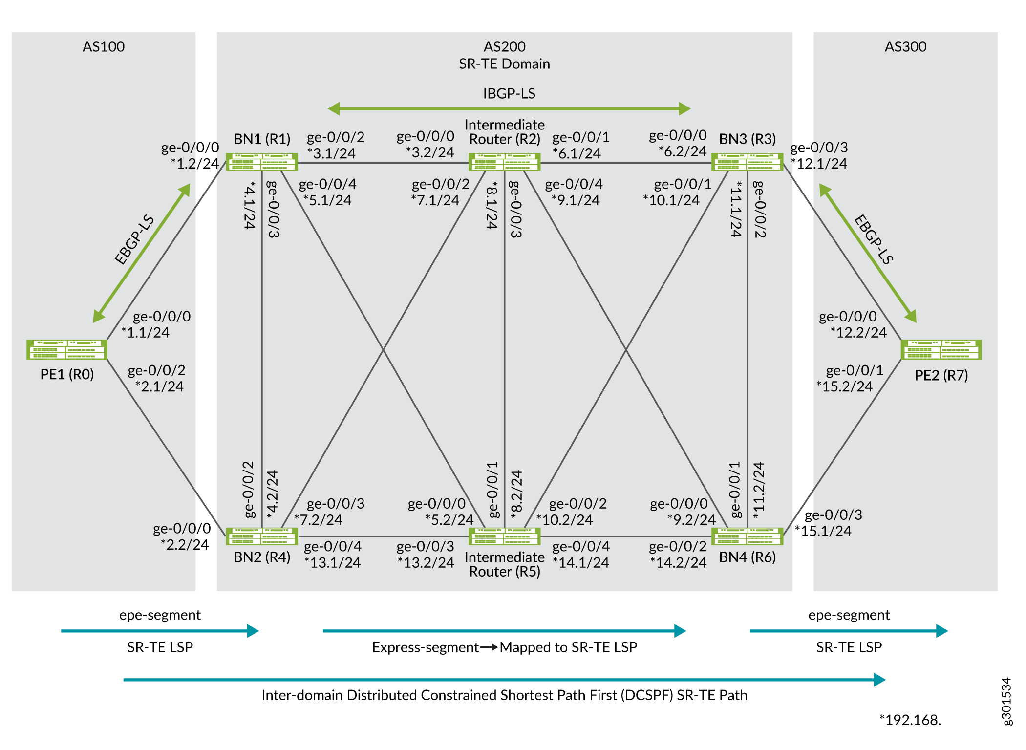
In this topology, an end-to-end SR-TE path between PE1 router to PE2 router is established. Egress peer engineering (EPE) segments are defined on PE1 and PE2 routers to steer traffic towards their directly connected border nodes BN1/BN2 and BN3/BN4, respectively. EPE segments defined on the border nodes are advertised internally through the BGP link state. These two SR-TE domains are interconnected through the domain (AS200) that is leveraging SR-TE LSPs for internal path establishment.
The border nodes of the AS200 domain facilitate the abstraction of SR-TE information between domains. Express segments are created on border nodes (BN1, BN2, BN3, and BN4). Express segments are created in a one-on-one relationship with the underlying SR-TE LSPs and all express segments are inserted into the border node's local TE database for subsequent BGP link-state advertisement. The AS200 domain leverages SR-TE LSP underlays for TE management and presents those underlay SR-TE LSPs as express segments to the AS100 and the AS300 domains, enabling the domains to have end-to-end SR-TE LSP connectivity.
The following table describes the domains, routers, and connections in the topology:
|
Domain |
Devices |
Router ID/Lo) Address |
Connection Details |
|---|---|---|---|
|
AS65100 (EBGP-LS/ SR-TE LSP) |
R0(PE1 router) |
10.100.100.100 10.100.100.101 |
Connected to R1 (BN1 router) through interface ge-0/0/0, assigned IP address 192.168.1.1/24. Connected to R4 (BN2 router) through interface ge-0/0/2, assigned IP address 192.168.2.1/24. |
|
AS65200 (SR-TE LSP) |
R1(BN1 router) |
10.1.1.1 |
Connected to R0 (PE1 router) through interface ge-0/0/0, assigned IP address 192.168.1.2/24. Connected to R4 (BN2 router) through interface ge-0/0/3, assigned IP address 192.168.4.1/24. Connected to R2 (Intermediate router) through interface ge-0/0/2, assigned IP address 192.168.3.1/24. Connected to R5 (Intermediate router) through interface ge-0/0/4, assigned IP address 192.168.5.1/24. |
|
R4(BN2 router) |
10.4.4.4 |
Connected to R0 (PE1 router) through interface ge-0/0/0, assigned IP address 192.168.2.2/24. Connected to R1 (BN1 router) through interface ge-0/0/2, assigned IP address 192.168.4.2/24. Connected to R2 (Intermediate router) through interface ge-0/0/3, assigned IP address 192.168.7.1/24. Connected to R5 (Intermediate router) through interface ge-0/0/4, assigned IP address 192.168.13.1/24. |
|
|
R2(Intermediate router) |
10.2.2.2 |
Connected to R1 (BN1 router) through interface ge-0/0/0, assigned IP address 192.168.3.2/24. Connected to R4 (BN2 router) through interface ge-0/0/2, assigned IP address 192.168.7.1/24. Connected to R5 (Intermediate router) through interface ge-0/0/3, assigned IP address 192.168.8.1/24. Connected to R3 (BN3 router) through interface ge-0/0/1, assigned IP address 192.168.6.1/24. Connected to R6 (BN4 router) through interface ge-0/0/4, assigned IP address 192.168.9.1/24. |
|
|
R5(Intermediate router) |
10.5.5.5 |
Connected to R1 (BN1 router) through interface ge-0/0/0, assigned IP address 192.168.5.2/24. Connected to R4 (BN2 router) through interface ge-0/0/3, assigned IP address 192.168.13.2/24. Connected to R2 (Intermediate router) through interface ge-0/0/1, assigned IP address 192.168.8.2/24. Connected to R3 (BN3 router) through interface ge-0/0/2, assigned IP address 192.168.10.2/24. Connected to R6 (BN4 router) through interface ge-0/0/4, assigned IP address 192.168.14.1/24. |
|
|
R3(BN3 router) |
10.3.3.3 |
Connected to R7 (PE2 router) through interface ge-0/0/3, assigned IP address 192.168.12.1/24. Connected to R6 (BN4 router) through interface ge-0/0/2, assigned IP address 192.168.11.1/24. Connected to R2 (Intermediate router) through interface ge-0/0/0, assigned IP address 192.168.6.2/24. Connected to R5 (Intermediate router) through interface ge-0/0/1, assigned IP address 192.168.10.1/24. |
|
|
R6(BN4 router) |
10.6.6.6 |
Connected to R7 (PE2 router) through interface ge-0/0/3, assigned IP address 192.168.15.1/24. Connected to R3 (BN3 router) through interface ge-0/0/1, assigned IP address 192.168.11.2/24. Connected to R2 (Intermediate router) through interface ge-0/0/0, assigned IP address 192.168.9.2/24. Connected to R5 (Intermediate router) through interface ge-0/0/2, assigned IP address 192.168.14.2/24. |
|
|
AS65300(EBGP-LS/SR-TE LSP) |
R7(PE2 router) |
10.7.7.7 |
Connected to R3 (BN3 router) through interface ge-0/0/0, assigned IP address 192.168.12.2/24. Connected to R6 (BN4 router) through interface ge-0/0/1, assigned IP address 192.168.15.2/24. |
Configuration
To inter-connect a multi-domain network and establish an end-to-end SR path using express segments, perform these tasks:
- CLI Quick Configuration
- Configure R0 (PE1 router)
- Configure R1 (BN1 router)
- Configure R4 (BN2 router)
- Configure R2 (Intermediate router)
- Configure R5 (Intermediate router)
- Configure R3 (BN3 router)
- Configure R6 (BN4 router)
- Configure R7 (PE2 router)
CLI Quick Configuration
To quickly configure this example,
copy the following commands, paste them into a text file, remove any line
breaks, change any details necessary to match your network configuration, copy
and paste the commands into the CLI at the [edit] hierarchy
level, and then enter commit from configuration
mode.
The quick configuration commands provided below can be used to configure express segments through uncolored SR-TE underlay path.
To configure colored SR-TE underlay path, you must do additional configurations on BN1 (R1), BN2 (R4), BN3 (R3), and BN4 (R6) routers. Below are the uncolored configurations for N1 (R1), BN2 (R4), BN3 (R3), and BN4 (R6) routers, you can find the additional colored configuration.
Configure R0 (PE1 router)Device R0 (PE1 router)
set interfaces ge-0/0/0 description To_R1_1
set interfaces ge-0/0/0 vlan-tagging
set interfaces ge-0/0/0 unit 0 vlan-id 1
set interfaces ge-0/0/0 unit 0 family inet address 192.168.1.1/24
set interfaces ge-0/0/0 unit 0 family iso
set interfaces ge-0/0/0 unit 0 family inet6 address 2001:db8:1000:10::100/64
set interfaces ge-0/0/0 unit 0 family mpls maximum-labels 8
set interfaces ge-0/0/2 description To_R4_1
set interfaces ge-0/0/2 vlan-tagging
set interfaces ge-0/0/2 unit 0 vlan-id 1
set interfaces ge-0/0/2 unit 0 family inet address 192.168.2.1/24
set interfaces ge-0/0/2 unit 0 family iso
set interfaces ge-0/0/2 unit 0 family inet6 address 2001:db8:4000:10::100/64
set interfaces ge-0/0/2 unit 0 family mpls maximum-labels 8
set interfaces lo0 unit 0 family inet address 10.100.100.100/32
set interfaces lo0 unit 0 family inet address 10.100.100.101/32
set interfaces lo0 unit 0 family iso address 49.0001.000a.0a0a.0a00
set interfaces lo0 unit 0 family inet6 address 2001:db8:abcd::10:100:100:100/128
set policy-options policy-statement bgplsepe_rt_2_ted term 1 from protocol bgp
set policy-options policy-statement bgplsepe_rt_2_ted term 1 then accept
set policy-options policy-statement direct from protocol direct
set policy-options policy-statement direct then accept
set policy-options policy-statement mpath then multipath-resolve
set policy-options policy-statement nlri2bgp term 1 from family traffic-engineering
set policy-options policy-statement nlri2bgp term 1 then accept
set policy-options policy-statement nlri2bgp_epe term 1 from family traffic-engineering
set policy-options policy-statement nlri2bgp_epe term 1 from protocol bgp-ls-epe
set policy-options policy-statement nlri2bgp_epe term 1 then next-hop self
set policy-options policy-statement nlri2bgp_epe term 1 then accept
set policy-options policy-statement nlri2ted_bgp term 1 from protocol bgp
set policy-options policy-statement nlri2ted_bgp term 1 then accept
set policy-options policy-statement nlri2ted_igp term 1 from traffic-engineering protocol isis-level-2
set policy-options policy-statement nlri2ted_igp term 1 then accept
set policy-options policy-statement pplb then load-balance per-packet
set policy-options policy-statement ted2nlri term 1 from protocol bgp-ls-epe
set policy-options policy-statement ted2nlri term 1 then accept
set policy-options policy-statement vpn1_res_map1 from route-filter 10.109.1/16 orlonger
set policy-options policy-statement vpn1_res_map1 then accept
set policy-options policy-statement vpn1_res_map1 then resolution-map map1
set policy-options policy-statement vpn2_res_map1 from route-filter 10.110.0.1/16 orlonger
set policy-options policy-statement vpn2_res_map1 then accept
set policy-options policy-statement vpn2_res_map1 then resolution-map map1
set policy-options community color7000 members color:0:7000
set policy-options community color7001 members color:0:7001
set policy-options resolution-map map1 mode ip-color
set routing-options router-id 10.100.100.100
set routing-options autonomous-system 100
set routing-options static route 10.7.7.71/32 next-hop 10.7.7.7
set routing-options static route 10.7.7.71/32 resolve
set protocols bgp group ebgp1 type external
set protocols bgp group ebgp1 multihop ttl 100
set protocols bgp group ebgp1 family inet unicast
set protocols bgp group ebgp1 family inet-vpn unicast
set protocols bgp group ebgp1 family traffic-engineering unicast
set protocols bgp group ebgp1 export nlri2bgp_epe
set protocols bgp group ebgp1 neighbor 192.168.1.2 peer-as 65200
set protocols bgp group ebgp1 neighbor 192.168.1.2 egress-te-adj-segment epe_adj1_toR1 label 7101
set protocols bgp group ebgp1 neighbor 192.168.1.2 egress-te-adj-segment epe_adj1_toR1 next-hop 192.168.1.2
set protocols bgp group ebgp1 neighbor 192.168.1.2 egress-te-adj-segment epe_adj1_toR1 te-link-attribute te-metric 20
set protocols bgp group ebgp1 neighbor 192.168.1.2 egress-te-adj-segment epe_adj1_toR1 te-link-attribute igp-metric 10
set protocols bgp group ebgp1 neighbor 192.168.1.2 egress-te-adj-segment epe_adj1_toR1 te-link-attribute admin-group [ red brown ]
set protocols bgp group ebgp1 neighbor 192.168.2.2 peer-as 65200
set protocols bgp group ebgp1 neighbor 192.168.2.2 egress-te-adj-segment epe_adj1_toR4 label 7104
set protocols bgp group ebgp1 neighbor 192.168.2.2 egress-te-adj-segment epe_adj1_toR4 next-hop 192.168.12.1192.168.2.2
set protocols bgp group ebgp1 neighbor 192.168.2.2 egress-te-adj-segment epe_adj1_toR4 te-link-attribute te-metric 20
set protocols bgp group ebgp1 neighbor 192.168.2.2 egress-te-adj-segment epe_adj1_toR4 te-link-attribute igp-metric 10
set protocols bgp group ebgp1 neighbor 192.168.2.2 egress-te-adj-segment epe_adj1_toR4 te-link-attribute admin-group [ red brown ]
set protocols bgp group ebgp1 neighbor 10.7.7.71 local-address 00.100.100.101
set protocols bgp group ebgp1 neighbor 10.7.7.71 import [ vpn1_res_map1 vpn2_res_map1 ]
set protocols bgp group ebgp1 neighbor 10.7.7.71 peer-as 65300
set protocols bgp group ebgp1 vpn-apply-export
set protocols isis interface lo0.0 passive
set protocols isis level 1 disable
set protocols isis level 2 wide-metrics-only
set protocols isis traffic-engineering l3-unicast-topology
set protocols isis traffic-engineering advertisement always
set protocols mpls traffic-engineering database import l3-unicast-topology bgp-link-state
set protocols mpls traffic-engineering database import policy ted2nlri
set protocols mpls traffic-engineering database export policy nlri2ted_bgp
set protocols mpls traffic-engineering database export l3-unicast-topology
set protocols mpls admin-groups red 0
set protocols mpls admin-groups blue 1
set protocols mpls admin-groups green 2
set protocols mpls admin-groups yellow 3
set protocols mpls admin-groups orange 4
set protocols mpls admin-groups brown 5
set protocols mpls admin-groups black 6
set protocols mpls admin-groups pink 7
set protocols mpls label-range static-label-range 1000 70000
set protocols mpls interface all
set protocols mpls interface fxp0.0 disable
set protocols mpls interface ge-0/0/0.0 admin-group [ red brown ]
set protocols source-packet-routing compute-profile compute1 no-label-stack-compression
set protocols source-packet-routing compute-profile ecompute1 no-label-stack-compression
set protocols source-packet-routing source-routing-path computelsp1 to 10.7.7.7
set protocols source-packet-routing source-routing-path computelsp1 install 10.7.7.71
set protocols source-packet-routing source-routing-path computelsp1 primary p1 compute compute1
set protocols source-packet-routing source-routing-path ecomputelsp1 to 10.7.7.7
set protocols source-packet-routing source-routing-path ecomputelsp1 color 7000
set protocols source-packet-routing source-routing-path ecomputelsp1 primary p1 compute ecompute1
Device R1 (BN1 router)
set interfaces ge-0/0/0 description To_R0_1
set interfaces ge-0/0/0 vlan-tagging
set interfaces ge-0/0/0 unit 0 vlan-id 1
set interfaces ge-0/0/0 unit 0 family inet address 192.168.1.2/24
set interfaces ge-0/0/0 unit 0 family iso
set interfaces ge-0/0/0 unit 0 family inet6 address 2001:db8:1000:10::1/64
set interfaces ge-0/0/0 unit 0 family mpls maximum-labels 8
set interfaces ge-0/0/0 unit 1 vlan-id 2
set interfaces ge-0/0/0 unit 1 family inet address 192.168.20.1/24
set interfaces ge-0/0/0 unit 1 family iso
set interfaces ge-0/0/0 unit 1 family inet6 address 2001:db8:1000:20::1/64
set interfaces ge-0/0/0 unit 1 family mpls maximum-labels 8
set interfaces ge-0/0/2 description To_R2
set interfaces ge-0/0/2 vlan-tagging
set interfaces ge-0/0/2 unit 0 vlan-id 1
set interfaces ge-0/0/2 unit 0 family inet address 192.168.3.1/24
set interfaces ge-0/0/2 unit 0 family iso
set interfaces ge-0/0/2 unit 0 family inet6 address 2001:db8:1200:10::1/64
set interfaces ge-0/0/2 unit 0 family mpls maximum-labels 8
set interfaces ge-0/0/2 unit 1 vlan-id 2
set interfaces ge-0/0/2 unit 1 family inet address 192.168.21.1/24
set interfaces ge-0/0/2 unit 1 family iso
set interfaces ge-0/0/2 unit 1 family inet6 address 2001:db8:1200:20::1/64
set interfaces ge-0/0/2 unit 1 family mpls maximum-labels 8
set interfaces ge-0/0/3 description to-R4
set interfaces ge-0/0/3 vlan-tagging
set interfaces ge-0/0/3 unit 0 vlan-id 1
set interfaces ge-0/0/3 unit 0 family inet address 192.168.4.1/24
set interfaces ge-0/0/3 unit 0 family iso
set interfaces ge-0/0/3 unit 0 family inet6 address 2001:db8:1400:10::1/64
set interfaces ge-0/0/3 unit 0 family mpls maximum-labels 8
set interfaces ge-0/0/4 description to-R5
set interfaces ge-0/0/4 vlan-tagging
set interfaces ge-0/0/4 unit 0 vlan-id 1
set interfaces ge-0/0/4 unit 0 family inet address 192.168.5.1/24
set interfaces ge-0/0/4 unit 0 family iso
set interfaces ge-0/0/4 unit 0 family inet6 address 2001:db8:1500:10::1/64
set interfaces ge-0/0/4 unit 0 family mpls maximum-labels 8
set interfaces ge-0/0/4 unit 1 vlan-id 2
set interfaces ge-0/0/4 unit 1 family inet address 192.168.22.1/24
set interfaces ge-0/0/4 unit 1 family iso
set interfaces ge-0/0/4 unit 1 family inet6 address 2001:db8:1500:20::1/64
set interfaces ge-0/0/4 unit 1 family mpls maximum-labels 8
set interfaces lo0 unit 0 family inet address 10.1.1.1/32
set interfaces lo0 unit 0 family iso address 49.0001.0001.0101.0100
set interfaces lo0 unit 0 family inet6 address 2001:db8:abcd::10:01:01:01/128
set policy-options policy-statement bgplsepe_rt_2_ted term 1 from protocol bgp
set policy-options policy-statement bgplsepe_rt_2_ted term 1 then accept
set policy-options policy-statement expresspolsr1 from protocol spring-te
set policy-options policy-statement expresspolsr1 from route-filter 10.3.3.3/32 exact
set policy-options policy-statement expresspolsr1 then accept
set policy-options policy-statement nlri2bgp term 1 from family traffic-engineering
set policy-options policy-statement nlri2bgp term 1 then next-hop self
set policy-options policy-statement nlri2bgp term 1 then accept
set policy-options policy-statement nlri2bgp_epe term 1 from family traffic-engineering
set policy-options policy-statement nlri2bgp_epe term 1 from protocol bgp-ls-epe
set policy-options policy-statement nlri2bgp_epe term 1 then next-hop self
set policy-options policy-statement nlri2bgp_epe term 1 then accept
set policy-options policy-statement nlri2bgp_stat term 1 from family traffic-engineering
set policy-options policy-statement nlri2bgp_stat term 1 from protocol express-segments
set policy-options policy-statement nlri2bgp_stat term 1 then accept
set policy-options policy-statement nlri2ted_igp term 1 from traffic-engineering protocol isis-level-2
set policy-options policy-statement nlri2ted_igp term 1 then accept
set policy-options policy-statement pplb then load-balance per-packet
set policy-options policy-statement prefix-sid term 1 from route-filter 10.1.1.1/32 exact
set policy-options policy-statement prefix-sid term 1 then prefix-segment index 1001
set policy-options policy-statement prefix-sid term 1 then prefix-segment node-segment
set policy-options policy-statement ted2nlri term 1 from protocol bgp-ls-epe
set policy-options policy-statement ted2nlri term 1 then accept
set policy-options policy-statement ted2nlri_epe_stat term 1 from family traffic-engineering
set policy-options policy-statement ted2nlri_epe_stat term 1 from protocol express-segments
set policy-options policy-statement ted2nlri_epe_stat term 1 then accept
set policy-options policy-statement ted2nlri_epe_stat term 2 from family traffic-engineering
set policy-options policy-statement ted2nlri_epe_stat term 2 from protocol bgp-ls-epe
set policy-options policy-statement ted2nlri_epe_stat term 2 then accept
set policy-options policy-statement ted2nlri_epe_stat term 3 from protocol isis
set policy-options policy-statement ted2nlri_epe_stat term 3 then reject
set policy-options policy-statement ted2nlri_igp term 1 from family traffic-engineering
set policy-options policy-statement ted2nlri_igp term 1 from protocol isis
set policy-options policy-statement ted2nlri_igp term 1 then accept
set routing-options router-id 10.1.1.1
set routing-options autonomous-system 65200
set routing-options forwarding-table export pplb
set protocols bgp group ebgp1 type external
set protocols bgp group ebgp1 family inet-vpn unicast
set protocols bgp group ebgp1 family traffic-engineering unicast
set protocols bgp group ebgp1 export nlri2bgp_stat
set protocols bgp group ebgp1 neighbor 192.168.1.1 peer-as 65100
set protocols bgp group ebgp1 neighbor 192.168.1.1 egress-te-adj-segment epe_adj1_toR0 label 8110
set protocols bgp group ebgp1 neighbor 192.168.1.1 egress-te-adj-segment epe_adj1_toR0 next-hop 192.168.1.1
set protocols bgp group ebgp1 neighbor 192.168.1.1 egress-te-adj-segment epe_adj1_toR0 te-link-attribute te-metric 20
set protocols bgp group ebgp1 neighbor 192.168.1.1 egress-te-adj-segment epe_adj1_toR0 te-link-attribute igp-metric 10
set protocols bgp group ebgp1 neighbor 192.168.1.1 egress-te-adj-segment epe_adj1_toR0 te-link-attribute admin-group [ red brown ]
set protocols bgp group ibgp1 type internal
set protocols bgp group ibgp1 local-address 10.1.1.1
set protocols bgp group ibgp1 family traffic-engineering unicast
set protocols bgp group ibgp1 export nlri2bgp_epe
set protocols bgp group ibgp1 neighbor 10.2.2.2
set protocols bgp group ibgp1 neighbor 10.5.5.5
set protocols express-segments segment-set set1sr membership-policy expresspolsr1
set protocols express-segments traffic-engineering
set protocols isis interface ge-0/0/0.0 passive
set protocols isis interface ge-0/0/0.1 passive
set protocols isis interface ge-0/0/2.0 level 2 lan-neighbor 0100.0202.0202 ipv4-adjacency-segment protected label 1211
set protocols isis interface ge-0/0/2.0 level 2 lan-neighbor 0100.0202.0202 ipv4-adjacency-segment unprotected label 1201
set protocols isis interface ge-0/0/2.0 level 2 post-convergence-lfa node-protection
set protocols isis interface ge-0/0/2.1 level 2 lan-neighbor 0100.0202.0202 ipv4-adjacency-segment protected label 1212
set protocols isis interface ge-0/0/2.1 level 2 lan-neighbor 0100.0202.0202 ipv4-adjacency-segment unprotected label 1202
set protocols isis interface ge-0/0/2.1 level 2 post-convergence-lfa node-protection
set protocols isis interface ge-0/0/3.0 level 2 lan-neighbor 0100.0404.0404 ipv4-adjacency-segment protected label 1411
set protocols isis interface ge-0/0/3.0 level 2 lan-neighbor 0100.0404.0404 ipv4-adjacency-segment unprotected label 1401
set protocols isis interface ge-0/0/3.0 level 2 post-convergence-lfa node-protection
set protocols isis interface ge-0/0/4.0 level 2 lan-neighbor 0100.0505.0505 ipv4-adjacency-segment protected label 1511
set protocols isis interface ge-0/0/4.0 level 2 lan-neighbor 0100.0505.0505 ipv4-adjacency-segment unprotected label 1501
set protocols isis interface ge-0/0/4.0 level 2 post-convergence-lfa node-protection
set protocols isis interface fxp0.0 disable
set protocols isis interface lo0.0 passive
set protocols isis source-packet-routing srgb start-label 800000 index-range 50000
set protocols isis level 1 disable
set protocols isis level 2 wide-metrics-only
set protocols isis backup-spf-options use-post-convergence-lfa
set protocols isis backup-spf-options use-source-packet-routing
set protocols isis traffic-engineering l3-unicast-topology
set protocols isis traffic-engineering advertisement always
set protocols isis export prefix-sid
set protocols mpls traffic-engineering database import l3-unicast-topology bgp-link-state
set protocols mpls traffic-engineering database import policy ted2nlri_epe_stat
set protocols mpls traffic-engineering database export l3-unicast-topology
set protocols mpls admin-groups red 0
set protocols mpls admin-groups blue 1
set protocols mpls admin-groups green 2
set protocols mpls admin-groups yellow 3
set protocols mpls admin-groups orange 4
set protocols mpls admin-groups brown 5
set protocols mpls admin-groups black 6
set protocols mpls admin-groups pink 7
set protocols mpls label-range static-label-range 1000 70000
set protocols mpls interface ge-0/0/3.0 admin-group red
set protocols mpls interface ge-0/0/2.0 admin-group brown
set protocols mpls interface ge-0/0/2.1 admin-group yellow
set protocols mpls interface ge-0/0/4.0 admin-group blue
set protocols mpls interface all
set protocols mpls interface fxp0.0 disable
set protocols source-packet-routing segment-list R1-R2-R3 hop1 label 1211
set protocols source-packet-routing segment-list R1-R2-R3 hop2 label 801003
set protocols source-packet-routing source-routing-path lsp1to3_sr to 10.3.3.3
set protocols source-packet-routing source-routing-path lsp1to3_sr primary R1-R2-R3
Configure the following additional commands in Device R1 (BN1 router) for colored SR-TE underlay path.
set routing-options rib-groups color-to-inet3 import-rib [ inetcolor.0 inet.3 ]
set protocols source-packet-routing no-chained-composite-next-hop
set protocols source-packet-routing source-routing-path lsp1to3_sr color 1000
set protocols source-packet-routing rib-group ipv4-color color-to-inet3
Device R4 (BN2 router)
set interfaces ge-0/0/0 description To_R0
set interfaces ge-0/0/0 vlan-tagging
set interfaces ge-0/0/0 unit 0 vlan-id 1
set interfaces ge-0/0/0 unit 0 family inet address 192.168.2.2/24
set interfaces ge-0/0/0 unit 0 family iso
set interfaces ge-0/0/0 unit 0 family inet6 address 2001:db8:4000:10::4/64
set interfaces ge-0/0/0 unit 0 family mpls maximum-labels 8
set interfaces ge-0/0/0 unit 1 vlan-id 2
set interfaces ge-0/0/0 unit 1 family inet address 192.168.40.2/24
set interfaces ge-0/0/0 unit 1 family iso
set interfaces ge-0/0/0 unit 1 family inet6 address 2001:db8:4000:20::4/64
set interfaces ge-0/0/0 unit 1 family mpls maximum-labels 8
set interfaces ge-0/0/2 description To_R1
set interfaces ge-0/0/2 vlan-tagging
set interfaces ge-0/0/2 unit 0 vlan-id 1
set interfaces ge-0/0/2 unit 0 family inet address 192.168.4.2/24
set interfaces ge-0/0/2 unit 0 family iso
set interfaces ge-0/0/2 unit 0 family inet6 address 2001:db8:1400:10::4/64
set interfaces ge-0/0/2 unit 0 family mpls maximum-labels 8
set interfaces ge-0/0/3 description To_R2
set interfaces ge-0/0/3 vlan-tagging
set interfaces ge-0/0/3 unit 0 vlan-id 1
set interfaces ge-0/0/3 unit 0 family inet address 192.168.7.1/24
set interfaces ge-0/0/3 unit 0 family iso
set interfaces ge-0/0/3 unit 0 family inet6 address 2001:db8:2400:10::4/64
set interfaces ge-0/0/3 unit 0 family mpls maximum-labels 8
set interfaces ge-0/0/3 unit 1 vlan-id 2
set interfaces ge-0/0/3 unit 1 family inet address 192.168.24.1/24
set interfaces ge-0/0/3 unit 1 family iso
set interfaces ge-0/0/3 unit 1 family inet6 address 2001:db8:2400:20::4/64
set interfaces ge-0/0/3 unit 1 family mpls maximum-labels 8
set interfaces ge-0/0/4 description To_R5
set interfaces ge-0/0/4 vlan-tagging
set interfaces ge-0/0/4 unit 0 vlan-id 1
set interfaces ge-0/0/4 unit 0 family inet address 192.168.13.1/24
set interfaces ge-0/0/4 unit 0 family iso
set interfaces ge-0/0/4 unit 0 family inet6 address 2001:db8:4500:10::4/64
set interfaces ge-0/0/4 unit 0 family mpls maximum-labels 8
set interfaces ge-0/0/4 unit 1 vlan-id 2
set interfaces ge-0/0/4 unit 1 family inet address 192.168.45.1/24
set interfaces ge-0/0/4 unit 1 family iso
set interfaces ge-0/0/4 unit 1 family inet6 address 2001:db8:4500:20::4/64
set interfaces ge-0/0/4 unit 1 family mpls maximum-labels 8
set interfaces lo0 unit 0 family inet address 10.4.4.4/32
set interfaces lo0 unit 0 family iso address 49.0001.0004.0404.0400
set interfaces lo0 unit 0 family inet6 address abcd::04:04:04:04/128
set policy-options policy-statement expresspolsr1 from protocol spring-te
set policy-options policy-statement expresspolsr1 from route-filter 10.6.6.6/32 exact
set policy-options policy-statement expresspolsr1 then accept
set policy-options policy-statement nlri2bgp_epe term 1 from family traffic-engineering
set policy-options policy-statement nlri2bgp_epe term 1 from protocol bgp-ls-epe
set policy-options policy-statement nlri2bgp_epe term 1 then next-hop self
set policy-options policy-statement nlri2bgp_epe term 1 then accept
set policy-options policy-statement nlri2bgp_stat term 1 from family traffic-engineering
set policy-options policy-statement nlri2bgp_stat term 1 from protocol express-segments
set policy-options policy-statement nlri2bgp_stat term 1 then accept
set policy-options policy-statement pplb then load-balance per-packet
set policy-options policy-statement prefix-sid term 1 from route-filter 10.4.4.4/32 exact
set policy-options policy-statement prefix-sid term 1 then prefix-segment index 1004
set policy-options policy-statement prefix-sid term 1 then prefix-segment node-segment
set policy-options policy-statement ted2nlri_epe_stat term 1 from family traffic-engineering
set policy-options policy-statement ted2nlri_epe_stat term 1 from protocol express-segments
set policy-options policy-statement ted2nlri_epe_stat term 1 then accept
set policy-options policy-statement ted2nlri_epe_stat term 2 from family traffic-engineering
set policy-options policy-statement ted2nlri_epe_stat term 2 from protocol bgp-ls-epe
set policy-options policy-statement ted2nlri_epe_stat term 2 then accept
set policy-options policy-statement ted2nlri_epe_stat term 3 from protocol isis
set policy-options policy-statement ted2nlri_epe_stat term 3 then reject
set routing-options router-id 10.4.4.4
set routing-options autonomous-system 65200

set routing-options forwarding-table export pplb
set protocols bgp group ibgp1 type internal
set protocols bgp group ibgp1 local-address 10.4.4.4
set protocols bgp group ibgp1 family traffic-engineering unicast
set protocols bgp group ibgp1 export nlri2bgp_epe
set protocols bgp group ibgp1 neighbor 10.2.2.2
set protocols bgp group ibgp1 neighbor 10.5.5.5
set protocols bgp group ebgp1 type external
set protocols bgp group ebgp1 family inet-vpn unicast
set protocols bgp group ebgp1 family traffic-engineering unicast
set protocols bgp group ebgp1 export nlri2bgp_stat
set protocols bgp group ebgp1 neighbor 192.168.2.1 peer-as 65100
set protocols bgp group ebgp1 neighbor 192.168.2.1 egress-te-adj-segment epe_adj1_toR0 label 8140
set protocols bgp group ebgp1 neighbor 192.168.2.1 egress-te-adj-segment epe_adj1_toR0 next-hop 192.168.2.1
set protocols bgp group ebgp1 neighbor 192.168.2.1 egress-te-adj-segment epe_adj1_toR0 te-link-attribute te-metric 20
set protocols bgp group ebgp1 neighbor 192.168.2.1 egress-te-adj-segment epe_adj1_toR0 te-link-attribute igp-metric 10
set protocols bgp group ebgp1 neighbor 192.168.2.1 egress-te-adj-segment epe_adj1_toR0 te-link-attribute admin-group [ red brown ]
set protocols express-segments segment-set set4sr membership-policy expresspolsr1
set protocols express-segments traffic-engineering
set protocols isis interface ge-0/0/0.0 level 2 post-convergence-lfa node-protection
set protocols isis interface ge-0/0/0.0 passive
set protocols isis interface ge-0/0/2.0 level 2 lan-neighbor 0100.0101.0101 ipv4-adjacency-segment protected label 4111
set protocols isis interface ge-0/0/2.0 level 2 lan-neighbor 0100.0101.0101 ipv4-adjacency-segment unprotected label 4101
set protocols isis interface ge-0/0/2.0 level 2 post-convergence-lfa node-protection
set protocols isis interface ge-0/0/3.0 level 2 lan-neighbor 0100.0202.0202 ipv4-adjacency-segment protected label 4211
set protocols isis interface ge-0/0/3.0 level 2 lan-neighbor 0100.0202.0202 ipv4-adjacency-segment unprotected label 4201
set protocols isis interface ge-0/0/3.0 level 2 post-convergence-lfa node-protection
set protocols isis interface ge-0/0/4.0 level 2 lan-neighbor 0100.0505.0505 ipv4-adjacency-segment protected label 4511
set protocols isis interface ge-0/0/4.0 level 2 lan-neighbor 0100.0505.0505 ipv4-adjacency-segment unprotected label 4501
set protocols isis interface ge-0/0/4.0 level 2 post-convergence-lfa node-protection
set protocols isis interface fxp0.0 disable
set protocols isis interface lo0.0 passive
set protocols isis source-packet-routing srgb start-label 800000 index-range 50000
set protocols isis level 1 disable
set protocols isis level 2 wide-metrics-only
set protocols isis backup-spf-options use-post-convergence-lfa
set protocols isis backup-spf-options use-source-packet-routing
set protocols isis traffic-engineering l3-unicast-topology
set protocols isis traffic-engineering advertisement always
set protocols isis export prefix-sid
set protocols mpls traffic-engineering database import l3-unicast-topology bgp-link-state
set protocols mpls traffic-engineering database import policy ted2nlri_epe_stat
set protocols mpls traffic-engineering database export l3-unicast-topology
set protocols mpls admin-groups red 0
set protocols mpls admin-groups blue 1
set protocols mpls admin-groups green 2
set protocols mpls admin-groups yellow 3
set protocols mpls admin-groups orange 4
set protocols mpls admin-groups brown 5
set protocols mpls admin-groups black 6
set protocols mpls admin-groups pink 7
set protocols mpls label-range static-label-range 1000 70000
set protocols mpls interface ge-0/0/2.0 admin-group red
set protocols mpls interface ge-0/0/3.0 admin-group green
set protocols mpls interface ge-0/0/4.0 admin-group brown
set protocols mpls interface all
set protocols mpls interface fxp0.0 disable
set protocols source-packet-routing segment-list R4-R5-R6 hop1 label 4511
set protocols source-packet-routing segment-list R4-R5-R6 hop2 label 5601
set protocols source-packet-routing source-routing-path lsp4to6_sr to 10.6.6.6
set protocols source-packet-routing source-routing-path lsp4to6_sr primary R4-R5-R6
Configure the following additional commands in Device R4 (BN2 router) for colored SR-TE underlay path.
set routing-options rib-groups color-to-inet3 import-rib [ inetcolor.0 inet.3 ]
set protocols source-packet-routing no-chained-composite-next-hop
set protocols source-packet-routing source-routing-path lsp4to6_sr color 1000
set protocols source-packet-routing rib-group ipv4-color color-to-inet3
Device R2 (Intermediate router)
set interfaces ge-0/0/0 description To_R1
set interfaces ge-0/0/0 vlan-tagging
set interfaces ge-0/0/0 unit 0 vlan-id 1
set interfaces ge-0/0/0 unit 0 family inet address 192.168.3.2/24
set interfaces ge-0/0/0 unit 0 family iso
set interfaces ge-0/0/0 unit 0 family inet6 address 2001:db8:1200:10::2/64
set interfaces ge-0/0/0 unit 0 family mpls maximum-labels 8
set interfaces ge-0/0/0 unit 1 vlan-id 2
set interfaces ge-0/0/0 unit 1 family inet address 192.168.21.2/24
set interfaces ge-0/0/0 unit 1 family iso
set interfaces ge-0/0/0 unit 1 family inet6 address 2001:db8:1200:20::2/64
set interfaces ge-0/0/0 unit 1 family mpls maximum-labels 8
set interfaces ge-0/0/1 description To_R3
set interfaces ge-0/0/1 vlan-tagging
set interfaces ge-0/0/1 unit 0 vlan-id 1
set interfaces ge-0/0/1 unit 0 family inet address 192.168.6.1/24
set interfaces ge-0/0/1 unit 0 family iso
set interfaces ge-0/0/1 unit 0 family inet6 address 2001:db8:2300:10::2/64
set interfaces ge-0/0/1 unit 0 family mpls maximum-labels 8
set interfaces ge-0/0/1 unit 1 vlan-id 2
set interfaces ge-0/0/1 unit 1 family inet address 192.168.23.1/24
set interfaces ge-0/0/1 unit 1 family iso
set interfaces ge-0/0/1 unit 1 family inet6 address 2001:db8:2300:20::2/64
set interfaces ge-0/0/1 unit 1 family mpls maximum-labels 8
set interfaces ge-0/0/2 description To_R4
set interfaces ge-0/0/2 vlan-tagging
set interfaces ge-0/0/2 unit 0 vlan-id 1
set interfaces ge-0/0/2 unit 0 family inet address 192.168.7.1/24
set interfaces ge-0/0/2 unit 0 family iso
set interfaces ge-0/0/2 unit 0 family inet6 address 2001:db8:2400:10::2/64
set interfaces ge-0/0/2 unit 0 family mpls maximum-labels 8
set interfaces ge-0/0/2 unit 1 vlan-id 2
set interfaces ge-0/0/2 unit 1 family inet address 192.168.24.1/24
set interfaces ge-0/0/2 unit 1 family iso
set interfaces ge-0/0/2 unit 1 family inet6 address 2001:db8:2400:20::2/64
set interfaces ge-0/0/2 unit 1 family mpls maximum-labels 8
set interfaces ge-0/0/3 description To_R5
set interfaces ge-0/0/3 vlan-tagging
set interfaces ge-0/0/3 unit 0 vlan-id 1
set interfaces ge-0/0/3 unit 0 family inet address 192.168.8.1/24
set interfaces ge-0/0/3 unit 0 family iso
set interfaces ge-0/0/3 unit 0 family inet6 address 2001:db8:2500:10::2/64
set interfaces ge-0/0/3 unit 0 family mpls maximum-labels 8
set interfaces ge-0/0/4 description To_R6
set interfaces ge-0/0/4 vlan-tagging
set interfaces ge-0/0/4 unit 0 vlan-id 1
set interfaces ge-0/0/4 unit 0 family inet address 192.168.9.1/24
set interfaces ge-0/0/4 unit 0 family iso
set interfaces ge-0/0/4 unit 0 family inet6 address 2001:db8:2600:10::2/64
set interfaces ge-0/0/4 unit 0 family mpls maximum-labels 8
set interfaces ge-0/0/4 unit 1 vlan-id 2
set interfaces ge-0/0/4 unit 1 family inet address 192.168.26.1/24
set interfaces ge-0/0/4 unit 1 family iso
set interfaces ge-0/0/4 unit 1 family inet6 address 2001:db8:2600:20::2/64
set interfaces ge-0/0/4 unit 1 family mpls maximum-labels 8
set interfaces lo0 unit 0 family inet address 10.2.2.2/32
set interfaces lo0 unit 0 family iso address 49.0001.0002.0202.0200
set interfaces lo0 unit 0 family inet6 address 2001:db8:abcd::02:02:02:02/128
set policy-options policy-statement bgplsepe_rt_2_ted term 1 from protocol bgp
set policy-options policy-statement bgplsepe_rt_2_ted term 1 then accept
set policy-options policy-statement nlri2bgp term 1 from family traffic-engineering
set policy-options policy-statement nlri2bgp term 1 then next-hop self
set policy-options policy-statement nlri2bgp term 1 then accept
set policy-options policy-statement nlri2bgp_igp term 1 from family traffic-engineering
set policy-options policy-statement nlri2bgp_igp term 1 from protocol isis
set policy-options policy-statement nlri2bgp_igp term 1 then accept
set policy-options policy-statement nlri2ted_igp term 1 from traffic-engineering protocol isis-level-2
set policy-options policy-statement nlri2ted_igp term 1 then accept
set policy-options policy-statement pplb then load-balance per-packet
set policy-options policy-statement prefix-sid term 1 from route-filter 10.2.2.2/32 exact
set policy-options policy-statement prefix-sid term 1 then prefix-segment index 1002
set policy-options policy-statement prefix-sid term 1 then prefix-segment node-segment
set policy-options policy-statement ted2nlri term 1 from protocol bgp-ls-epe
set policy-options policy-statement ted2nlri term 1 then accept
set policy-options policy-statement ted2nlri_1 term 1 from traffic-engineering
set policy-options policy-statement ted2nlri_1 term 1 then accept
set policy-options policy-statement ted2nlri_igp term 1 from family traffic-engineering
set policy-options policy-statement ted2nlri_igp term 1 from protocol isis
set policy-options policy-statement ted2nlri_igp term 1 then accept
set routing-options router-id 10.2.2.2
set routing-options autonomous-system 65200
set routing-options forwarding-table export pplb
set protocols bgp group RR1 type internal
set protocols bgp group RR1 local-address 10.2.2.2
set protocols bgp group RR1 family traffic-engineering unicast
set protocols bgp group RR1 neighbor 10.1.1.1
set protocols bgp group RR1 neighbor 10.3.3.3
set protocols bgp group RR1 neighbor 10.6.6.6
set protocols bgp group RR1 neighbor 10.4.4.4
set protocols bgp cluster 10.2.2.2
set protocols isis interface ge-0/0/0.0 level 2 lan-neighbor 0100.0101.0101 ipv4-adjacency-segment protected label 2111
set protocols isis interface ge-0/0/0.0 level 2 lan-neighbor 0100.0101.0101 ipv4-adjacency-segment unprotected label 2101
set protocols isis interface ge-0/0/0.0 level 2 post-convergence-lfa node-protection
set protocols isis interface ge-0/0/0.1 level 2 lan-neighbor 0100.0101.0101 ipv4-adjacency-segment protected label 2112
set protocols isis interface ge-0/0/0.1 level 2 lan-neighbor 0100.0101.0101 ipv4-adjacency-segment unprotected label 2102
set protocols isis interface ge-0/0/0.1 level 2 post-convergence-lfa node-protection
set protocols isis interface ge-0/0/1.0 level 2 lan-neighbor 0100.0303.0303 ipv4-adjacency-segment protected label 2311
set protocols isis interface ge-0/0/1.0 level 2 lan-neighbor 0100.0303.0303 ipv4-adjacency-segment unprotected label 2301
set protocols isis interface ge-0/0/1.0 level 2 post-convergence-lfa node-protection
set protocols isis interface ge-0/0/2.0 level 2 lan-neighbor 0100.0404.0404 ipv4-adjacency-segment protected label 2411
set protocols isis interface ge-0/0/2.0 level 2 lan-neighbor 0100.0404.0404 ipv4-adjacency-segment unprotected label 2401
set protocols isis interface ge-0/0/2.0 level 2 post-convergence-lfa node-protection
set protocols isis interface ge-0/0/3.0 level 2 lan-neighbor 0100.0505.0505 ipv4-adjacency-segment protected label 2511
set protocols isis interface ge-0/0/3.0 level 2 lan-neighbor 0100.0505.0505 ipv4-adjacency-segment unprotected label 2501
set protocols isis interface ge-0/0/3.0 level 2 post-convergence-lfa node-protection
set protocols isis interface ge-0/0/4.0 level 2 lan-neighbor 0100.0606.0606 ipv4-adjacency-segment protected label 2611
set protocols isis interface ge-0/0/4.0 level 2 lan-neighbor 0100.0606.0606 ipv4-adjacency-segment unprotected label 2601
set protocols isis interface ge-0/0/4.0 level 2 post-convergence-lfa node-protection
set protocols isis interface fxp0.0 disable
set protocols isis interface lo0.0 passive
set protocols isis source-packet-routing srgb start-label 800000 index-range 50000
set protocols isis level 1 disable
set protocols isis level 2 wide-metrics-only
set protocols isis backup-spf-options use-post-convergence-lfa
set protocols isis backup-spf-options use-source-packet-routing
set protocols isis traffic-engineering l3-unicast-topology
set protocols isis traffic-engineering advertisement always
set protocols isis export prefix-sid
set protocols mpls admin-groups red 0
set protocols mpls admin-groups blue 1
set protocols mpls admin-groups green 2
set protocols mpls admin-groups yellow 3
set protocols mpls admin-groups orange 4
set protocols mpls admin-groups brown 5
set protocols mpls admin-groups black 6
set protocols mpls admin-groups pink 7
set protocols mpls label-range static-label-range 1000 70000
set protocols mpls interface ge-0/0/0.0 admin-group brown
set protocols mpls interface ge-0/0/0.1 admin-group yellow
set protocols mpls interface ge-0/0/2.0 admin-group green
set protocols mpls interface ge-0/0/3.0 admin-group red
set protocols mpls interface ge-0/0/4.0 admin-group blue
set protocols mpls interface ge-0/0/1.0 admin-group brown
set protocols mpls interface all
set protocols mpls interface fxp0.0 disable
Device R5 (Intermediate router)
set interfaces ge-0/0/0 description To_R1
set interfaces ge-0/0/0 vlan-tagging
set interfaces ge-0/0/0 unit 0 vlan-id 1
set interfaces ge-0/0/0 unit 0 family inet address 192.168.5.2/24
set interfaces ge-0/0/0 unit 0 family iso
set interfaces ge-0/0/0 unit 0 family inet6 address 2001:db8:1500:10::5/64
set interfaces ge-0/0/0 unit 0 family mpls maximum-labels 8
set interfaces ge-0/0/0 unit 1 vlan-id 2
set interfaces ge-0/0/0 unit 1 family inet address 192.168.22.2/24
set interfaces ge-0/0/0 unit 1 family iso
set interfaces ge-0/0/0 unit 1 family inet6 address 2001:db8:1500:20::5/64
set interfaces ge-0/0/0 unit 1 family mpls maximum-labels 8
set interfaces ge-0/0/1 description To_R2
set interfaces ge-0/0/1 vlan-tagging
set interfaces ge-0/0/1 unit 0 vlan-id 1
set interfaces ge-0/0/1 unit 0 family inet address 192.168.8.2/24
set interfaces ge-0/0/1 unit 0 family iso
set interfaces ge-0/0/1 unit 0 family inet6 address 2001:db8:2500:10::5/64
set interfaces ge-0/0/1 unit 0 family mpls maximum-labels 8
set interfaces ge-0/0/2 description To_R3
set interfaces ge-0/0/2 vlan-tagging
set interfaces ge-0/0/2 unit 0 vlan-id 1
set interfaces ge-0/0/2 unit 0 family inet address 192.168.10.2/24
set interfaces ge-0/0/2 unit 0 family iso
set interfaces ge-0/0/2 unit 0 family inet6 address 2001:db8:3500:10::5/64
set interfaces ge-0/0/2 unit 0 family mpls maximum-labels 8
set interfaces ge-0/0/2 unit 1 vlan-id 2
set interfaces ge-0/0/2 unit 1 family inet address 192.168.35.2/24
set interfaces ge-0/0/2 unit 1 family iso
set interfaces ge-0/0/2 unit 1 family inet6 address 2001:db8:3500:20::5/64
set interfaces ge-0/0/2 unit 1 family mpls maximum-labels 8
set interfaces ge-0/0/3 description To_R4
set interfaces ge-0/0/3 vlan-tagging
set interfaces ge-0/0/3 unit 0 vlan-id 1
set interfaces ge-0/0/3 unit 0 family inet address 192.168.13.2/24
set interfaces ge-0/0/3 unit 0 family iso
set interfaces ge-0/0/3 unit 0 family inet6 address 2001:db8:4500:10::5/64
set interfaces ge-0/0/3 unit 0 family mpls maximum-labels 8
set interfaces ge-0/0/3 unit 1 vlan-id 2
set interfaces ge-0/0/3 unit 1 family inet address 192.168.45.2/24
set interfaces ge-0/0/3 unit 1 family iso
set interfaces ge-0/0/3 unit 1 family inet6 address 2001:db8:4500:20::5/64
set interfaces ge-0/0/3 unit 1 family mpls maximum-labels 8
set interfaces ge-0/0/4 description To_R6
set interfaces ge-0/0/4 vlan-tagging
set interfaces ge-0/0/4 unit 0 vlan-id 1
set interfaces ge-0/0/4 unit 0 family inet address 192.168.14.1/24
set interfaces ge-0/0/4 unit 0 family iso
set interfaces ge-0/0/4 unit 0 family inet6 address 2001:db8:5600:10::5/64
set interfaces ge-0/0/4 unit 0 family mpls maximum-labels 8
set interfaces ge-0/0/4 unit 1 vlan-id 2
set interfaces ge-0/0/4 unit 1 family inet address 192.168.56.1/24
set interfaces ge-0/0/4 unit 1 family iso
set interfaces ge-0/0/4 unit 1 family inet6 address 2001:db8:5600:20::5/64
set interfaces ge-0/0/4 unit 1 family mpls maximum-labels 8
set interfaces lo0 unit 0 family inet address 10.5.5.5/32
set interfaces lo0 unit 0 family iso address 49.0001.0005.0505.0500
set interfaces lo0 unit 0 family inet6 address 2001:db8:abcd::05:05:05:05/128
set policy-options policy-statement nlri2bgp term 1 from family traffic-engineering
set policy-options policy-statement nlri2bgp term 1 then next-hop self
set policy-options policy-statement nlri2bgp term 1 then accept
set policy-options policy-statement nlri2ted_igp term 1 from traffic-engineering protocol isis-level-2
set policy-options policy-statement nlri2ted_igp term 1 then accept
set policy-options policy-statement pplb then load-balance per-packet
set policy-options policy-statement prefix-sid term 1 from route-filter 10.5.5.5/32 exact
set policy-options policy-statement prefix-sid term 1 then prefix-segment index 1005
set policy-options policy-statement prefix-sid term 1 then prefix-segment node-segment
set policy-options policy-statement ted2nlri term 1 from protocol bgp-ls-epe
set policy-options policy-statement ted2nlri term 1 then accept
set policy-options policy-statement ted2nlri_igp term 1 from family traffic-engineering
set policy-options policy-statement ted2nlri_igp term 1 from protocol isis
set policy-options policy-statement ted2nlri_igp term 1 then accept
set routing-options router-id 10.5.5.5
set routing-options autonomous-system 65200
set routing-options forwarding-table export pplb
set protocols bgp group RR2 type internal
set protocols bgp group RR2 family inet unicast
set protocols bgp group RR2 family traffic-engineering unicast
set protocols bgp group RR2 neighbor 10.1.1.1
set protocols bgp group RR2 neighbor 10.3.3.3
set protocols bgp group RR2 neighbor 10.6.6.6
set protocols bgp group RR2 neighbor 10.4.4.4
set protocols bgp cluster 10.5.5.5
set protocols isis interface ge-0/0/0.0 level 2 lan-neighbor 0100.0101.0101 ipv4-adjacency-segment protected label 5111
set protocols isis interface ge-0/0/0.0 level 2 lan-neighbor 0100.0101.0101 ipv4-adjacency-segment unprotected label 5101
set protocols isis interface ge-0/0/0.0 level 2 post-convergence-lfa node-protection
set protocols isis interface ge-0/0/1.0 level 2 lan-neighbor 0100.0202.0202 ipv4-adjacency-segment protected label 5211
set protocols isis interface ge-0/0/1.0 level 2 lan-neighbor 0100.0202.0202 ipv4-adjacency-segment unprotected label 5201
set protocols isis interface ge-0/0/1.0 level 2 post-convergence-lfa node-protection
set protocols isis interface ge-0/0/2.0 level 2 lan-neighbor 0100.0303.0303 ipv4-adjacency-segment protected label 5311
set protocols isis interface ge-0/0/2.0 level 2 lan-neighbor 0100.0303.0303 ipv4-adjacency-segment unprotected label 5301
set protocols isis interface ge-0/0/2.0 level 2 post-convergence-lfa node-protection
set protocols isis interface ge-0/0/3.0 level 2 lan-neighbor 0100.0404.0404 ipv4-adjacency-segment protected label 5411
set protocols isis interface ge-0/0/3.0 level 2 lan-neighbor 0100.0404.0404 ipv4-adjacency-segment unprotected label 5401
set protocols isis interface ge-0/0/3.0 level 2 post-convergence-lfa node-protection
set protocols isis interface ge-0/0/4.0 level 2 lan-neighbor 0100.0606.0606 ipv4-adjacency-segment protected label 5611
set protocols isis interface ge-0/0/4.0 level 2 lan-neighbor 0100.0606.0606 ipv4-adjacency-segment unprotected label 5601
set protocols isis interface ge-0/0/4.0 level 2 post-convergence-lfa node-protection
set protocols isis interface fxp0.0 disable
set protocols isis interface lo0.0 passive
set protocols isis source-packet-routing srgb start-label 800000 index-range 50000
set protocols isis level 1 disable
set protocols isis backup-spf-options use-post-convergence-lfa
set protocols isis backup-spf-options use-source-packet-routing
set protocols isis traffic-engineering l3-unicast-topology
set protocols isis traffic-engineering advertisement always
set protocols isis export prefix-sid
set protocols mpls admin-groups red 0
set protocols mpls admin-groups blue 1
set protocols mpls admin-groups green 2
set protocols mpls admin-groups yellow 3
set protocols mpls admin-groups orange 4
set protocols mpls admin-groups brown 5
set protocols mpls admin-groups black 6
set protocols mpls admin-groups pink 7
set protocols mpls label-range static-label-range 1000 70000
set protocols mpls interface ge-0/0/0.0 admin-group blue
set protocols mpls interface ge-0/0/1.0 admin-group red
set protocols mpls interface ge-0/0/2.0 admin-group green
set protocols mpls interface ge-0/0/3.0 admin-group brown
set protocols mpls interface ge-0/0/4.0 admin-group brown
set protocols mpls interface all
set protocols mpls interface fxp0.0 disable
Device R3 (BN3 router)
set interfaces ge-0/0/0 description To_R2
set interfaces ge-0/0/0 vlan-tagging
set interfaces ge-0/0/0 unit 0 vlan-id 1
set interfaces ge-0/0/0 unit 0 family inet address 192.168.6.2/24
set interfaces ge-0/0/0 unit 0 family iso
set interfaces ge-0/0/0 unit 0 family inet6 address 2001:db8:2300:10::3/64
set interfaces ge-0/0/0 unit 0 family mpls maximum-labels 8
set interfaces ge-0/0/0 unit 1 vlan-id 2
set interfaces ge-0/0/0 unit 1 family inet address 192.168.23.2/24
set interfaces ge-0/0/0 unit 1 family iso
set interfaces ge-0/0/0 unit 1 family inet6 address 2001:db8:2300:20::3/64
set interfaces ge-0/0/0 unit 1 family mpls maximum-labels 8
set interfaces ge-0/0/0 unit 2 vlan-id 3
set interfaces ge-0/0/0 unit 2 family inet address 192.168.30.2/24
set interfaces ge-0/0/0 unit 2 family iso
set interfaces ge-0/0/0 unit 2 family inet6 address 2001:db8:2300:30::3/64
set interfaces ge-0/0/0 unit 2 family mpls maximum-labels 8
set interfaces ge-0/0/1 description To_R5
set interfaces ge-0/0/1 vlan-tagging
set interfaces ge-0/0/1 unit 0 vlan-id 1
set interfaces ge-0/0/1 unit 0 family inet address 192.168.10.1/24
set interfaces ge-0/0/1 unit 0 family iso
set interfaces ge-0/0/1 unit 0 family inet6 address 2001:db8:3500:10::3/64
set interfaces ge-0/0/1 unit 0 family mpls maximum-labels 8
set interfaces ge-0/0/1 unit 1 vlan-id 2
set interfaces ge-0/0/1 unit 1 family inet address 192.168.35.1/24
set interfaces ge-0/0/1 unit 1 family iso
set interfaces ge-0/0/1 unit 1 family inet6 address 2001:db8:3500:20::3/64
set interfaces ge-0/0/1 unit 1 family mpls maximum-labels 8
set interfaces ge-0/0/2 description To_R6
set interfaces ge-0/0/2 vlan-tagging
set interfaces ge-0/0/2 unit 0 vlan-id 1
set interfaces ge-0/0/2 unit 0 family inet address 192.168.11.1/24
set interfaces ge-0/0/2 unit 0 family iso
set interfaces ge-0/0/2 unit 0 family inet6 address 2001:db8:3600:10::3/64
set interfaces ge-0/0/2 unit 0 family mpls maximum-labels 8
set interfaces ge-0/0/3 description To_R7
set interfaces ge-0/0/3 vlan-tagging
set interfaces ge-0/0/3 unit 0 vlan-id 1
set interfaces ge-0/0/3 unit 0 family inet address 192.168.12.1/24
set interfaces ge-0/0/3 unit 0 family iso
set interfaces ge-0/0/3 unit 0 family inet6 address 2001:db8:3700:10::3/6
set interfaces ge-0/0/3 unit 0 family mpls maximum-labels 8
set interfaces ge-0/0/3 unit 1 vlan-id 2
set interfaces ge-0/0/3 unit 1 family inet address 192.168.37.1/24
set interfaces ge-0/0/3 unit 1 family iso
set interfaces ge-0/0/3 unit 1 family inet6 address 2001:db8:3700:20::3/6
set interfaces ge-0/0/3 unit 1 family mpls maximum-labels 8
set interfaces lo0 unit 0 family inet address 10.3.3.3/32
set interfaces lo0 unit 0 family iso address 49.0001.0003.0303.0300
set interfaces lo0 unit 0 family inet6 address 2001:db8:abcd::03:03:03:03/128
set policy-options policy-statement bgplsepe_rt_2_ted term 1 from protocol bgp
set policy-options policy-statement bgplsepe_rt_2_ted term 1 then accept
set policy-options policy-statement expresspol1 from route-filter 10.1.1.1/32 exact install-nexthop lsp lsp3to1_a
set policy-options policy-statement expresspol1 then accept
set policy-options policy-statement expresspol2 from route-filter 10.4.4.4/32 exact install-nexthop lsp lsp3to4_a
set policy-options policy-statement expresspol2 then accept
set policy-options policy-statement expresspolsr1 from protocol spring-te
set policy-options policy-statement expresspolsr1 from route-filter 10.1.1.1/32 exact
set policy-options policy-statement expresspolsr1 then accept
set policy-options policy-statement nlri2bgp term 1 from family traffic-engineering
set policy-options policy-statement nlri2bgp term 1 then next-hop self
set policy-options policy-statement nlri2bgp term 1 then accept
set policy-options policy-statement nlri2bgp_epe term 1 from family traffic-engineering
set policy-options policy-statement nlri2bgp_epe term 1 from protocol bgp-ls-epe
set policy-options policy-statement nlri2bgp_epe term 1 then next-hop self
set policy-options policy-statement nlri2bgp_epe term 1 then accept
set policy-options policy-statement nlri2bgp_igp term 1 from family traffic-engineering
set policy-options policy-statement nlri2bgp_igp term 1 from protocol isis
set policy-options policy-statement nlri2bgp_igp term 1 then accept
set policy-options policy-statement nlri2bgp_stat term 1 from family traffic-engineering
set policy-options policy-statement nlri2bgp_stat term 1 from protocol express-segments
set policy-options policy-statement nlri2bgp_stat term 1 then accept
set policy-options policy-statement pplb then load-balance per-packet
set policy-options policy-statement prefix-sid term 1 from route-filter 10.3.3.3/32 exact
set policy-options policy-statement prefix-sid term 1 then prefix-segment index 1003
set policy-options policy-statement prefix-sid term 1 then prefix-segment node-segment
set policy-options policy-statement ted2nlri term 1 from protocol bgp-ls-epe
set policy-options policy-statement ted2nlri term 1 then accept
set policy-options policy-statement ted2nlri_epe_stat term 1 from family traffic-engineering
set policy-options policy-statement ted2nlri_epe_stat term 1 from protocol static
set policy-options policy-statement ted2nlri_epe_stat term 1 then accept
set policy-options policy-statement ted2nlri_epe_stat term 2 from family traffic-engineering
set policy-options policy-statement ted2nlri_epe_stat term 2 from protocol bgp-ls-epe
set policy-options policy-statement ted2nlri_epe_stat term 2 then accept
set policy-options policy-statement ted2nlri_epe_stat term 3 from protocol isis
set policy-options policy-statement ted2nlri_epe_stat term 3 then reject
set policy-options policy-statement ted2nlri_igp from family traffic-engineering
set policy-options policy-statement ted2nlri_igp from protocol isis
set policy-options policy-statement ted2nlri_igp then accept
set routing-options router-id 10.3.3.3
set routing-options autonomous-system 65200
set routing-options forwarding-table export pplb
set protocols bgp group ibgp1 type internal
set protocols bgp group ibgp1 local-address 10.3.3.3
set protocols bgp group ibgp1 family traffic-engineering unicast
set protocols bgp group ibgp1 export nlri2bgp_epe
set protocols bgp group ibgp1 neighbor 10.2.2.2
set protocols bgp group ibgp1 neighbor 10.5.5.5
set protocols bgp group ebgp1 type external
set protocols bgp group ebgp1 family traffic-engineering unicast
set protocols bgp group ebgp1 export nlri2bgp_stat
set protocols bgp group ebgp1 neighbor 192.168.12.2 peer-as 65300
set protocols bgp group ebgp1 neighbor 192.168.12.2 egress-te-adj-segment epe_adj1_toR7 label 7137
set protocols bgp group ebgp1 neighbor 192.168.12.2 egress-te-adj-segment epe_adj1_toR7 next-hop 192.168.12.2
set protocols bgp group ebgp1 neighbor 192.168.12.2 egress-te-adj-segment epe_adj1_toR7 te-link-attribute te-metric 20
set protocols bgp group ebgp1 neighbor 192.168.12.2 egress-te-adj-segment epe_adj1_toR7 te-link-attribute igp-metric 10
set protocols bgp group ebgp1 neighbor 192.168.12.2 egress-te-adj-segment epe_adj1_toR7 te-link-attribute admin-group [ red brown ]
set protocols bgp group ebgp1 vpn-apply-export
set protocols express-segments segment-set set3sr membership-policy expresspolsr1
set protocols express-segments traffic-engineering
set protocols isis interface ge-0/0/0.0 level 2 lan-neighbor 0100.0202.0202 ipv4-adjacency-segment protected label 3211
set protocols isis interface ge-0/0/0.0 level 2 lan-neighbor 0100.0202.0202 ipv4-adjacency-segment unprotected label 3201
set protocols isis interface ge-0/0/0.0 level 2 post-convergence-lfa node-protection
set protocols isis interface ge-0/0/1.0 level 2 lan-neighbor 0100.0505.0505 ipv4-adjacency-segment protected label 3511
set protocols isis interface ge-0/0/1.0 level 2 lan-neighbor 0100.0505.0505 ipv4-adjacency-segment unprotected label 3501
set protocols isis interface ge-0/0/1.0 level 2 post-convergence-lfa node-protection
set protocols isis interface ge-0/0/2.0 level 2 lan-neighbor 0100.0606.0606 ipv4-adjacency-segment protected label 3611
set protocols isis interface ge-0/0/2.0 level 2 lan-neighbor 0100.0606.0606 ipv4-adjacency-segment unprotected label 3601
set protocols isis interface ge-0/0/2.0 level 2 post-convergence-lfa node-protection
set protocols isis interface ge-0/0/3.0 passive
set protocols isis interface fxp0.0 disable
set protocols isis interface lo0.0 passive
set protocols isis source-packet-routing srgb start-label 800000 index-range 50000
set protocols isis level 1 disable
set protocols isis level 2 wide-metrics-only
set protocols isis backup-spf-options use-post-convergence-lfa
set protocols isis backup-spf-options use-source-packet-routing
set protocols isis traffic-engineering l3-unicast-topology
set protocols isis traffic-engineering advertisement always
set protocols isis export prefix-sid
set protocols mpls traffic-engineering database import l3-unicast-topology bgp-link-state
set protocols mpls traffic-engineering database import policy ted2nlri_epe_stat
set protocols mpls traffic-engineering database export l3-unicast-topology
set protocols mpls admin-groups red 0
set protocols mpls admin-groups blue 1
set protocols mpls admin-groups green 2
set protocols mpls admin-groups yellow 3
set protocols mpls admin-groups orange 4
set protocols mpls admin-groups brown 5
set protocols mpls admin-groups black 6
set protocols mpls admin-groups pink 7
set protocols mpls label-range static-label-range 1000 70000
set protocols mpls interface ge-0/0/0.0 admin-group brown
set protocols mpls interface ge-0/0/1.0 admin-group green
set protocols mpls interface ge-0/0/2.0 admin-group red
set protocols mpls interface ge-0/0/3.0 admin-group [ red brown ]
set protocols mpls interface all
set protocols mpls interface fxp0.0 disableset protocols source-packet-routing segment-list R3-R2-R1 inherit-label-nexthops
set protocols source-packet-routing segment-list R3-R2-R1 auto-translate
set protocols source-packet-routing segment-list R3-R2-R1 hop1 ip-address 192.168.6.1
set protocols source-packet-routing segment-list R3-R2-R1 hop2 ip-address 192.168.3.1
set protocols source-packet-routing source-routing-path lsp3to1_sr to 10.1.1.1
set protocols source-packet-routing source-routing-path lsp3to1_sr primary R3-R2-R1
Configure the following additional commands in Device R3 (BN3 router) for colored SR-TE underlay path.
set routing-options rib-groups color-to-inet3 import-rib [ inetcolor.0 inet.3 ]
set protocols source-packet-routing no-chained-composite-next-hop
set protocols source-packet-routing source-routing-path lsp3to1_sr color 1000
set protocols source-packet-routing rib-group ipv4-color color-to-inet3
Device R6 (BN4 router)
set interfaces ge-0/0/0 description To_R0
set interfaces ge-0/0/0 vlan-tagging
set interfaces ge-0/0/0 unit 0 vlan-id 1
set interfaces ge-0/0/0 unit 0 family inet address 192.168.12.1192.168.2.2/24
set interfaces ge-0/0/0 unit 0 family iso
set interfaces ge-0/0/0 unit 0 family inet6 address 2001:db8:4000:10::4/64
set interfaces ge-0/0/0 unit 0 family mpls maximum-labels 8
set interfaces ge-0/0/0 unit 1 vlan-id 2
set interfaces ge-0/0/0 unit 1 family inet address 192.168.40.2/24
set interfaces ge-0/0/0 unit 1 family iso
set interfaces ge-0/0/0 unit 1 family inet6 address 2001:db8:4000:20::4/64
set interfaces ge-0/0/0 unit 1 family mpls maximum-labels 8
set interfaces ge-0/0/2 description To_R1
set interfaces ge-0/0/2 vlan-tagging
set interfaces ge-0/0/2 unit 0 vlan-id 1
set interfaces ge-0/0/2 unit 0 family inet address 192.168.4.2/24
set interfaces ge-0/0/2 unit 0 family iso
set interfaces ge-0/0/2 unit 0 family inet6 address 2001:db8:1400:10::4/64
set interfaces ge-0/0/2 unit 0 family mpls maximum-labels 8
set interfaces ge-0/0/3 description To_R2
set interfaces ge-0/0/3 vlan-tagging
set interfaces ge-0/0/3 unit 0 vlan-id 1
set interfaces ge-0/0/3 unit 0 family inet address 192.168.7.1/24
set interfaces ge-0/0/3 unit 0 family iso
set interfaces ge-0/0/3 unit 0 family inet6 address 2001:db8:2400:10::4/64
set interfaces ge-0/0/3 unit 0 family mpls maximum-labels 8
set interfaces ge-0/0/3 unit 1 vlan-id 2
set interfaces ge-0/0/3 unit 1 family inet address 192.168.24.1/24
set interfaces ge-0/0/3 unit 1 family iso
set interfaces ge-0/0/3 unit 1 family inet6 address 2001:db8:2400:20::4/64
set interfaces ge-0/0/3 unit 1 family mpls maximum-labels 8
set interfaces ge-0/0/4 description To_R5
set interfaces ge-0/0/4 vlan-tagging
set interfaces ge-0/0/4 unit 0 vlan-id 1
set interfaces ge-0/0/4 unit 0 family inet address 192.168.13.1/24
set interfaces ge-0/0/4 unit 0 family iso
set interfaces ge-0/0/4 unit 0 family inet6 address 2001:db8:4500:10::4/64
set interfaces ge-0/0/4 unit 0 family mpls maximum-labels 8
set interfaces ge-0/0/4 unit 1 vlan-id 2
set interfaces ge-0/0/4 unit 1 family inet address 192.168.45.1/24
set interfaces ge-0/0/4 unit 1 family iso
set interfaces ge-0/0/4 unit 1 family inet6 address 2001:db8:4500:20::4/64
set interfaces ge-0/0/4 unit 1 family mpls maximum-labels 8
set interfaces lo0 unit 0 family inet address 10.4.4.4/32
set interfaces lo0 unit 0 family iso address 49.0001.0004.0404.0400
set interfaces lo0 unit 0 family inet6 address 2001:db8:abcd::04:04:04:04/128
set policy-options policy-statement expresspolsr1 from protocol spring-te
set policy-options policy-statement expresspolsr1 from route-filter 10.6.6.6/32 exact
set policy-options policy-statement expresspolsr1 then accept
set policy-options policy-statement nlri2bgp_epe term 1 from family traffic-engineering
set policy-options policy-statement nlri2bgp_epe term 1 from protocol bgp-ls-epe
set policy-options policy-statement nlri2bgp_epe term 1 then next-hop self
set policy-options policy-statement nlri2bgp_epe term 1 then accept
set policy-options policy-statement nlri2bgp_stat term 1 from family traffic-engineering
set policy-options policy-statement nlri2bgp_stat term 1 from protocol express-segments
set policy-options policy-statement nlri2bgp_stat term 1 then accept
set policy-options policy-statement pplb then load-balance per-packet
set policy-options policy-statement prefix-sid term 1 from route-filter 10.4.4.4/32 exact
set policy-options policy-statement prefix-sid term 1 then prefix-segment index 1004
set policy-options policy-statement prefix-sid term 1 then prefix-segment node-segment
set policy-options policy-statement ted2nlri_epe_stat term 1 from family traffic-engineering
set policy-options policy-statement ted2nlri_epe_stat term 1 from protocol express-segments
set policy-options policy-statement ted2nlri_epe_stat term 1 then accept
set policy-options policy-statement ted2nlri_epe_stat term 2 from family traffic-engineering
set policy-options policy-statement ted2nlri_epe_stat term 2 from protocol bgp-ls-epe
set policy-options policy-statement ted2nlri_epe_stat term 2 then accept
set policy-options policy-statement ted2nlri_epe_stat term 3 from protocol isis
set policy-options policy-statement ted2nlri_epe_stat term 3 then reject
set routing-options router-id 10.4.4.4
set routing-options autonomous-system 65200
set routing-options forwarding-table export pplb
set protocols bgp group ibgp1 type internal
set protocols bgp group ibgp1 local-address 10.4.4.4
set protocols bgp group ibgp1 family traffic-engineering unicast
set protocols bgp group ibgp1 export nlri2bgp_epe
set protocols bgp group ibgp1 neighbor 10.2.2.2
set protocols bgp group ibgp1 neighbor 10.5.5.5
set protocols bgp group ebgp1 type external
set protocols bgp group ebgp1 family inet-vpn unicast
set protocols bgp group ebgp1 family traffic-engineering unicast
set protocols bgp group ebgp1 export nlri2bgp_stat
set protocols bgp group ebgp1 neighbor 192.168.2.1 peer-as 65100
set protocols bgp group ebgp1 neighbor 192.168.2.1 egress-te-adj-segment epe_adj1_toR0 label 8140
set protocols bgp group ebgp1 neighbor 192.168.2.1 egress-te-adj-segment epe_adj1_toR0 next-hop 192.168.2.1
set protocols bgp group ebgp1 neighbor 192.168.2.1 egress-te-adj-segment epe_adj1_toR0 te-link-attribute te-metric 20
set protocols bgp group ebgp1 neighbor 192.168.2.1 egress-te-adj-segment epe_adj1_toR0 te-link-attribute igp-metric 10
set protocols bgp group ebgp1 neighbor 192.168.2.1 egress-te-adj-segment epe_adj1_toR0 te-link-attribute admin-group [ red brown ]
set protocols express-segments segment-set set4sr membership-policy expresspolsr1
set protocols express-segments traffic-engineering
set protocols isis interface ge-0/0/0.0 level 2 post-convergence-lfa node-protection
set protocols isis interface ge-0/0/0.0 passive
set protocols isis interface ge-0/0/2.0 level 2 lan-neighbor 0100.0101.0101 ipv4-adjacency-segment protected label 4111
set protocols isis interface ge-0/0/2.0 level 2 lan-neighbor 0100.0101.0101 ipv4-adjacency-segment unprotected label 4101
set protocols isis interface ge-0/0/2.0 level 2 post-convergence-lfa node-protection
set protocols isis interface ge-0/0/3.0 level 2 lan-neighbor 0100.0202.0202 ipv4-adjacency-segment protected label 4211
set protocols isis interface ge-0/0/3.0 level 2 lan-neighbor 0100.0202.0202 ipv4-adjacency-segment unprotected label 4201
set protocols isis interface ge-0/0/3.0 level 2 post-convergence-lfa node-protection
set protocols isis interface ge-0/0/4.0 level 2 lan-neighbor 0100.0505.0505 ipv4-adjacency-segment protected label 4511
set protocols isis interface ge-0/0/4.0 level 2 lan-neighbor 0100.0505.0505 ipv4-adjacency-segment unprotected label 4501
set protocols isis interface ge-0/0/4.0 level 2 post-convergence-lfa node-protection
set protocols isis interface fxp0.0 disable
set protocols isis interface lo0.0 passive
set protocols isis source-packet-routing srgb start-label 800000 index-range 50000
set protocols isis level 1 disable
set protocols isis level 2 wide-metrics-only
set protocols isis backup-spf-options use-post-convergence-lfa
set protocols isis backup-spf-options use-source-packet-routing
set protocols isis traffic-engineering l3-unicast-topology
set protocols isis traffic-engineering advertisement always
set protocols isis export prefix-sid
set protocols mpls traffic-engineering database import l3-unicast-topology bgp-link-state
set protocols mpls traffic-engineering database import policy ted2nlri_epe_stat
set protocols mpls traffic-engineering database export l3-unicast-topology
set protocols mpls admin-groups red 0
set protocols mpls admin-groups blue 1
set protocols mpls admin-groups green 2
set protocols mpls admin-groups yellow 3
set protocols mpls admin-groups orange 4
set protocols mpls admin-groups brown 5
set protocols mpls admin-groups black 6
set protocols mpls admin-groups pink 7
set protocols mpls label-range static-label-range 1000 70000
set protocols mpls interface ge-0/0/2.0 admin-group red
set protocols mpls interface ge-0/0/3.0 admin-group green
set protocols mpls interface ge-0/0/4.0 admin-group brown
set protocols mpls interface all
set protocols mpls interface fxp0.0 disable
set protocols source-packet-routing segment-list R4-R5-R6 hop1 label 4511
set protocols source-packet-routing segment-list R4-R5-R6 hop2 label 5601
set protocols source-packet-routing source-routing-path lsp4to6_sr to 10.6.6.6
set protocols source-packet-routing source-routing-path lsp4to6_sr primary R4-R5-R6
Configure the following additional commands in Device R6 (BN4 router) for colored SR-TE underlay path.
set routing-options rib-groups color-to-inet3 import-rib [ inetcolor.0 inet.3 ]
set protocols source-packet-routing no-chained-composite-next-hop
set protocols source-packet-routing source-routing-path lsp6to4_sr color 1000
set protocols source-packet-routing rib-group ipv4-color color-to-inet3
Device R7 (PE2 router)
set interfaces ge-0/0/0 description To_R3
set interfaces ge-0/0/0 vlan-tagging
set interfaces ge-0/0/0 unit 0 vlan-id 1
set interfaces ge-0/0/0 unit 0 family inet address 192.168.12.2/24
set interfaces ge-0/0/0 unit 0 family iso
set interfaces ge-0/0/0 unit 0 family inet6 address 2001:db8:3700:10::7/64
set interfaces ge-0/0/0 unit 0 family mpls maximum-labels 8
set interfaces ge-0/0/0 unit 1 vlan-id 2
set interfaces ge-0/0/0 unit 1 family inet address 192.168.37.2/24
set interfaces ge-0/0/0 unit 1 family iso
set interfaces ge-0/0/0 unit 1 family inet6 address 2001:db8:3700:20::7/64
set interfaces ge-0/0/0 unit 1 family mpls maximum-labels 8
set interfaces ge-0/0/1 description To_R6
set interfaces ge-0/0/1 vlan-tagging
set interfaces ge-0/0/1 unit 0 vlan-id 1
set interfaces ge-0/0/1 unit 0 family inet address 192.168.15.2/24
set interfaces ge-0/0/1 unit 0 family iso
set interfaces ge-0/0/1 unit 0 family inet6 address 2001:db8:6700:10::7/64
set interfaces ge-0/0/1 unit 0 family mpls maximum-labels 8
set interfaces ge-0/0/1 unit 1 vlan-id 2
set interfaces ge-0/0/1 unit 1 family inet address 192.168.67.2/24
set interfaces ge-0/0/1 unit 1 family iso
set interfaces ge-0/0/1 unit 1 family inet6 address 2001:db8:6700:20::7/64
set interfaces ge-0/0/1 unit 1 family mpls maximum-labels 8
set interfaces lo0 unit 0 family inet address 10.7.7.7/32
set interfaces lo0 unit 0 family inet address 10.7.7.71/32
set interfaces lo0 unit 0 family iso address 49.0001.0007.0707.0700
set interfaces lo0 unit 0 family inet6 address 2001:db8:abcd::07:07:07:07/128
set interfaces lo0 unit 0 family inet6 address 2001:db8:abcd::7:7:7:71/128
set policy-options policy-statement bgplsepe_rt_2_ted term 1 from protocol bgp
set policy-options policy-statement bgplsepe_rt_2_ted term 1 then accept
set policy-options policy-statement direct from protocol direct
set policy-options policy-statement direct then accept
set policy-options policy-statement mpath then multipath-resolve
set policy-options policy-statement nlri2bgp term 1 from family traffic-engineering
set policy-options policy-statement nlri2bgp term 1 then accept
set policy-options policy-statement nlri2bgp_epe term 1 from family traffic-engineering
set policy-options policy-statement nlri2bgp_epe term 1 from protocol bgp-ls-epe
set policy-options policy-statement nlri2bgp_epe term 1 then next-hop self
set policy-options policy-statement nlri2bgp_epe term 1 then accept
set policy-options policy-statement nlri2ted_bgp term 1 from protocol bgp
set policy-options policy-statement nlri2ted_bgp term 1 then accept
set policy-options policy-statement nlri2ted_igp term 1 from traffic-engineering protocol isis-level-2
set policy-options policy-statement nlri2ted_igp term 1 then accept
set policy-options policy-statement payload_vpn_109 term 1 from route-filter 10.109.0.1/16 orlonger
set policy-options policy-statement payload_vpn_109 term 1 then community add color7000
set policy-options policy-statement payload_vpn_109 term 1 then next-hop 10.7.7.7
set policy-options policy-statement payload_vpn_109 term 1 then accept
set policy-options policy-statement payload_vpn_110 term 1 from route-filter 10.110.0.1/16 orlonger
set policy-options policy-statement payload_vpn_110 term 1 then community add color7001
set policy-options policy-statement payload_vpn_110 term 1 then next-hop 10.7.7.7
set policy-options policy-statement payload_vpn_110 term 1 then accept
set policy-options policy-statement pplb then load-balance per-packet
set policy-options policy-statement ted2nlri term 1 from protocol bgp-ls-epe
set policy-options policy-statement ted2nlri term 1 then accept
set policy-options community color7000 members color:0:7000
set policy-options community color7001 members color:0:7001
set policy-options resolution-map map1 mode ip-color
set routing-options router-id 10.7.7.7
set routing-options autonomous-system 65300
set routing-options static route 10.100.100.101/32 next-hop 10.100.100.100
set routing-options static route 10.100.100.101/32 resolve
set routing-options forwarding-table export pplb
set protocols bgp group ebgp1 type external
set protocols bgp group ebgp1 multihop ttl 100
set protocols bgp group ebgp1 family inet unicast
set protocols bgp group ebgp1 family inet-vpn unicast
set protocols bgp group ebgp1 family traffic-engineering unicast
set protocols bgp group ebgp1 export [ nlri2bgp_epe payload_vpn_109 payload_vpn_110 ]
set protocols bgp group ebgp1 neighbor 192.168.12.1 peer-as 200
set protocols bgp group ebgp1 neighbor 192.168.12.1 egress-te-adj-segment epe_adj1_toR3 label 8173
set protocols bgp group ebgp1 neighbor 192.168.12.1 egress-te-adj-segment epe_adj1_toR3 next-hop 192.168.12.1
set protocols bgp group ebgp1 neighbor 192.168.12.1 egress-te-adj-segment epe_adj1_toR3 te-link-attribute te-metric 20
set protocols bgp group ebgp1 neighbor 192.168.12.1 egress-te-adj-segment epe_adj1_toR3 te-link-attribute igp-metric 10
set protocols bgp group ebgp1 neighbor 192.168.12.1 egress-te-adj-segment epe_adj1_toR3 te-link-attribute admin-group [ red brown ]
set protocols bgp group ebgp1 neighbor 192.168.15.1 peer-as 200
set protocols bgp group ebgp1 neighbor 192.168.15.1 egress-te-adj-segment epe_adj1_toR6 label 8176
set protocols bgp group ebgp1 neighbor 192.168.15.1 egress-te-adj-segment epe_adj1_toR6 next-hop 192.168.15.1
set protocols bgp group ebgp1 neighbor 192.168.15.1 egress-te-adj-segment epe_adj1_toR6 te-link-attribute te-metric 20
set protocols bgp group ebgp1 neighbor 192.168.15.1 egress-te-adj-segment epe_adj1_toR6 te-link-attribute igp-metric 10
set protocols bgp group ebgp1 neighbor 192.168.15.1 egress-te-adj-segment epe_adj1_toR6 te-link-attribute admin-group [ red brown ]
set protocols bgp group ebgp1 neighbor 10.100.100.101 local-address 10.7.7.71
set protocols bgp group ebgp1 neighbor 10.100.100.101 peer-as 65100
set protocols bgp group ebgp1 vpn-apply-export
set protocols bgp group to-CE1 type external
set protocols bgp group to-CE1 local-address 192.168.50.1
set protocols bgp group to-CE1 neighbor 192.168.50.2 family inet unicast
set protocols bgp group to-CE1 neighbor 192.168.50.2 family inet6 unicast
set protocols bgp group to-CE1 neighbor 192.168.50.2 peer-as 700
set protocols bgp group to-CE1 neighbor 192.168.50.2 local-as 300
set protocols isis interface fxp0.0 disable
set protocols isis interface lo0.0 passive
set protocols isis level 1 disable
set protocols isis level 2 wide-metrics-only
set protocols isis traffic-engineering l3-unicast-topology
set protocols isis traffic-engineering advertisement always
set protocols mpls traffic-engineering database import l3-unicast-topology bgp-link-state
set protocols mpls traffic-engineering database import policy ted2nlri
set protocols mpls traffic-engineering database export policy nlri2ted_bgp
set protocols mpls traffic-engineering database export l3-unicast-topology
set protocols mpls admin-groups red 0
set protocols mpls admin-groups blue 1
set protocols mpls admin-groups green 2
set protocols mpls admin-groups yellow 3
set protocols mpls admin-groups orange 4
set protocols mpls admin-groups brown 5
set protocols mpls admin-groups black 6
set protocols mpls admin-groups pink 7
set protocols mpls label-range static-label-range 1000 70000
set protocols mpls interface ge-0/0/1.0 admin-group [ red brown ]
set protocols mpls interface ge-0/0/0.0 admin-group [ red brown ]
set protocols mpls interface all
set protocols mpls interface fxp0.0 disable
set protocols source-packet-routing compute-profile compute1 no-label-stack-compression
set protocols source-packet-routing source-routing-path computelsp1 to 10.100.100.100
set protocols source-packet-routing source-routing-path computelsp1 install 10.100.100.101
set protocols source-packet-routing source-routing-path computelsp1 primary p1 compute compute1
Configure R0 (PE1 router)
Step-by-Step Procedure
The following example requires you to navigate various levels in the configuration hierarchy. For information about navigating the CLI, see Using the CLI Editor in Configuration Mode in the CLI User Guide.
To configure device R0:
-
Configure the network services mode as Enhanced IP. Enhanced IP sets the router's network services to enhanced Internet Protocol and uses enhanced mode capabilities.
[edit]
user@R0#set chassis network-services enhanced-ip
After you configure the
enhanced-ipstatement and commit the configuration, the following warning message appears prompting you to reboot the router:'chassis' WARNING: Chassis configuration for network services has been changed. A system reboot is mandatory. Please reboot the system NOW. Continuing without a reboot might result in unexpected system behavior. commit complete
The reboot brings up the FPCs on the router.
-
Configure the interfaces to enable IP, MPLS, and ISO transport.
[edit]
user@R0#set interfaces ge-0/0/0 description To_R1_1
user@R0#set interfaces ge-0/0/0 vlan-tagging
user@R0#set interfaces ge-0/0/0 unit 0 vlan-id 1
user@R0#set interfaces ge-0/0/0 unit 0 family inet address 192.168.1.1/24
user@R0#set interfaces ge-0/0/0 unit 0 family iso
user@R0#set interfaces ge-0/0/0 unit 0 family inet6 address 2001:db8:1000:10::100/64
user@R0#set interfaces ge-0/0/0 unit 0 family mpls maximum-labels 8
user@R0#set interfaces ge-0/0/2 description To_R4_1
user@R0#set interfaces ge-0/0/2 vlan-tagging
user@R0#set interfaces ge-0/0/2 unit 0 vlan-id 1
user@R0#set interfaces ge-0/0/2 unit 0 family inet address 192.168.2.1/24
user@R0#set interfaces ge-0/0/2 unit 0 family iso
user@R0#set interfaces ge-0/0/2 unit 0 family inet6 address 2001:db8:4000:10::100/64
user@R0#set interfaces ge-0/0/2 unit 0 family mpls maximum-labels 8
-
Configure the loopback interface to enable tunnel endpoints and service endpoints.
[edit]
user@R0#set interfaces lo0 unit 0 family inet address 10.100.100.100/32
user@R0#set interfaces lo0 unit 0 family inet address 10.100.100.101/32
user@R0#set interfaces lo0 unit 0 family iso address 49.0001.000a.0a0a.0a00
user@R0#set interfaces lo0 unit 0 family inet6 address 2001:db8:abcd::10:100:100:100/128
-
Define import and export policies. For example, configure policies that export EPE TE links from the local TE database to lsdist.0 and policies to import from lsdist.0 into the local TE database. You can configure policies to advertise the BGP routes to a peer.
Route filter routs are advertised from external AS.
[edit]
user@R0#set policy-options policy-statement bgplsepe_rt_2_ted term 1 from protocol bgp
user@R0#set policy-options policy-statement bgplsepe_rt_2_ted term 1 then accept
user@R0#set policy-options policy-statement direct from protocol direct
user@R0#set policy-options policy-statement direct then accept
user@R0#set policy-options policy-statement mpath then multipath-resolve
user@R0#set policy-options policy-statement nlri2bgp term 1 from family traffic-engineering
user@R0#set policy-options policy-statement nlri2bgp term 1 then accept
user@R0#set policy-options policy-statement nlri2bgp_epe term 1 from family traffic-engineering
user@R0#set policy-options policy-statement nlri2bgp_epe term 1 from protocol bgp-ls-epe
user@R0#set policy-options policy-statement nlri2bgp_epe term 1 then next-hop self
user@R0#set policy-options policy-statement nlri2bgp_epe term 1 then accept
user@R0#set policy-options policy-statement nlri2ted_bgp term 1 from protocol bgp
user@R0#set policy-options policy-statement nlri2ted_bgp term 1 then accept
user@R0#set policy-options policy-statement nlri2ted_igp term 1 from traffic-engineering protocol isis-level-2
user@R0#set policy-options policy-statement nlri2ted_igp term 1 then accept
user@R0#set policy-options policy-statement pplb then load-balance per-packet
user@R0#set policy-options policy-statement ted2nlri term 1 from protocol bgp-ls-epe
user@R0#set policy-options policy-statement ted2nlri term 1 then accept
user@R0#set policy-options policy-statement vpn1_res_map1 from route-filter 10.1090.1/16 orlonger
user@R0#set policy-options policy-statement vpn1_res_map1 then accept
user@R0#set policy-options policy-statement vpn1_res_map1 then resolution-map map1
user@R0#set policy-options policy-statement vpn2_res_map1 from route-filter 10.110.0.1/16 orlonger
user@R0#set policy-options policy-statement vpn2_res_map1 then accept
user@R0#set policy-options policy-statement vpn2_res_map1 then resolution-map map1
-
Configure policy-options of community to add color attributes and set resolution map.
[edit]
user@R0#set policy-options community color7000 members color:0:7000
user@R0#set policy-options community color7001 members color:0:7001
user@R0#set policy-options resolution-map map1 mode ip-color
-
Configure routing options to identify the router in the domain.
[edit]
user@R0#set routing-options router-id 100.100.100.100
user@R0#set routing-options autonomous-system 100
user@R0#set routing-options static route 10.7.7.71/32 next-hop 10.7.7.7
user@R0#set routing-options static route 10.7.7.71/32 resolve
-
Configure BGP to enable BGP-LS route advertisement to the connected peers and define the EPE links. Since express segment is an internal TE link, this configuration creates an external TE link.
[edit]
user@R0#set protocols bgp group ebgp1 type external
user@R0#set protocols bgp group ebgp1 multihop ttl 100
user@R0#set protocols bgp group ebgp1 family inet unicast
user@R0#set protocols bgp group ebgp1 family inet-vpn unicast
user@R0#set protocols bgp group ebgp1 family traffic-engineering unicast
user@R0#set protocols bgp group ebgp1 export nlri2bgp_epe
user@R0#set protocols bgp group ebgp1 neighbor 192.168.1.2 peer-as 65200
user@R0#set protocols bgp group ebgp1 neighbor 192.168.1.2 egress-te-adj-segment epe_adj1_toR1 label 7101
user@R0#set protocols bgp group ebgp1 neighbor 192.168.1.2 egress-te-adj-segment epe_adj1_toR1 next-hop 192.168.1.2
user@R0#set protocols bgp group ebgp1 neighbor 192.168.1.2 egress-te-adj-segment epe_adj1_toR1 te-link-attribute te-metric 20
user@R0#set protocols bgp group ebgp1 neighbor 192.168.1.2 egress-te-adj-segment epe_adj1_toR1 te-link-attribute igp-metric 10
user@R0#set protocols bgp group ebgp1 neighbor 192.168.1.2 egress-te-adj-segment epe_adj1_toR1 te-link-attribute admin-group red
user@R0#set protocols bgp group ebgp1 neighbor 192.168.1.2 egress-te-adj-segment epe_adj1_toR1 te-link-attribute admin-group brown
user@R0#set protocols bgp group ebgp1 neighbor 192.168.2.2 peer-as 65200
user@R0#set protocols bgp group ebgp1 neighbor 192.168.2.2 egress-te-adj-segment epe_adj1_toR4 label 7104
user@R0#set protocols bgp group ebgp1 neighbor 192.168.2.2 egress-te-adj-segment epe_adj1_toR4 next-hop 192.168.2.2
user@R0#set protocols bgp group ebgp1 neighbor 192.168.2.2 egress-te-adj-segment epe_adj1_toR4 te-link-attribute te-metric 20
user@R0#set protocols bgp group ebgp1 neighbor 192.168.2.2 egress-te-adj-segment epe_adj1_toR4 te-link-attribute igp-metric 10
user@R0#set protocols bgp group ebgp1 neighbor 192.168.2.2 egress-te-adj-segment epe_adj1_toR4 te-link-attribute admin-group red
user@R0#set protocols bgp group ebgp1 neighbor 192.168.2.2 egress-te-adj-segment epe_adj1_toR4 te-link-attribute admin-group brown
user@R0#set protocols bgp group ebgp1 neighbor 10.7.7.71 local-address 10.100.100.101
user@R0#set protocols bgp group ebgp1 neighbor 10.7.7.71 import [ vpn1_res_map1 vpn2_res_map1 ]
user@R0#set protocols bgp group ebgp1 neighbor 10.7.7.71 peer-as 65300
user@R0#set protocols bgp group ebgp1 vpn-apply-export
-
Configure IS-IS protocol.
[edit]
user@R0#set protocols isis interface lo0.0 passive
user@R0#set protocols isis level 1 disable
user@R0#set protocols isis level 2 wide-metrics-only
user@R0#set protocols isis traffic-engineering l3-unicast-topology
user@R0#set protocols isis traffic-engineering advertisement always
-
Enable import and export of traffic engineering database parameters using policies.
[edit]
user@R0#set protocols mpls traffic-engineering database import l3-unicast-topology bgp-link-state
user@R0#set protocols mpls traffic-engineering database import policy ted2nlri
user@R0#set protocols mpls traffic-engineering database export policy nlri2ted_bgp
user@R0#set protocols mpls traffic-engineering database export l3-unicast-topology
-
Configure MPLS administrative group policies for LSP path computation.
[edit]
user@R0#set protocols mpls admin-groups red 0
user@R0#set protocols mpls admin-groups blue 1
user@R0#set protocols mpls admin-groups green 2
user@R0#set protocols mpls admin-groups yellow 3
user@R0#set protocols mpls admin-groups orange 4
user@R0#set protocols mpls admin-groups brown 5
user@R0#set protocols mpls admin-groups black 6
user@R0#set protocols mpls admin-groups pink 7
-
Configure the MPLS label range to assign static labels for the EPE links.
[edit]
user@R0#set protocols mpls label-range static-label-range 1000 70000
-
Configure MPLS on the interfaces.
[edit]
user@R0#set protocols mpls interface all
user@R0#set protocols mpls interface fxp0.0 disable
user@R0#set protocols mpls interface ge-0/0/0.0 admin-group [ red brown ]
-
Configure SR-TE policies on the ingress router to enable end-to-end SR-TE policy.
[edit]
user@R0#set protocols source-packet-routing compute-profile compute1 no-label-stack-compression
user@R0#set protocols source-packet-routing compute-profile ecompute1 no-label-stack-compression
user@R0#set protocols source-packet-routing source-routing-path computelsp1 to 10.7.7.7
user@R0#set protocols source-packet-routing source-routing-path computelsp1 install 10.7.7.71
user@R0#set protocols source-packet-routing source-routing-path computelsp1 primary p1 compute compute1
user@R0#set protocols source-packet-routing source-routing-path ecomputelsp1 to 10.7.7.7
user@R0#set protocols source-packet-routing source-routing-path ecomputelsp1 color 7000
user@R0#set protocols source-packet-routing source-routing-path ecomputelsp1 primary p1 compute ecompute1
user@R0#set protocols source-packet-routing source-routing-path ecomputelsp2 to 10.7.7.7
Results
From configuration mode, confirm your configuration by entering the
show chassis, show interfaces,
show policy-optionsshow
routing-options, and show protocols commands.
If the output does not display the intended configuration, repeat the
instructions in this example to correct the configuration.
chassis {
    network-services enhanced-ip;
}
interfaces {
    ge-0/0/0 {
        description To_R1_1;
        vlan-tagging;
        unit 0 {
            vlan-id 1;
            family inet {
                address 192.168.1.1/24;
            }
            family iso;
            family inet6 {
                address 2001:db8:1000:10::100/64;
            }
            family mpls {
                maximum-labels 8;
            }
        }
    }
    ge-0/0/2 {
        description To_R4_1;
        vlan-tagging;
        unit 0 {
            vlan-id 1;
            family inet {
                address 192.168.2.1/24;
            }
            family iso;
            family inet6 {
                address 2001:db8:4000:10::100/64;
            }
            family mpls {
                maximum-labels 8;
            }
        }
    }
    lo0 {
        unit 0 {
            family inet {
                address 10.100.100.100/32;
                address 10.100.100.101/32;
            }
            family iso {
                address 49.0001.000a.0a0a.0a00;
            }
            family inet6 {
                address 2001:db8:abcd::10:100:100:100/128;
            }
        }
    }
}
policy-options {
    policy-statement bgplsepe_rt_2_ted {
        term 1 {
            from protocol bgp;
            then accept;
        }
    }
    policy-statement direct {
        from protocol direct;
        then accept;
    }
    policy-statement mpath {
        then multipath-resolve;
    }
    policy-statement nlri2bgp {
        term 1 {
            from family traffic-engineering;
            then accept;
        }
    }
    policy-statement nlri2bgp_epe {
        term 1 {
            from {
                family traffic-engineering;
                protocol bgp-ls-epe;
            }
            then {
                next-hop self;
                accept;
            }
        }
    }
    policy-statement nlri2ted_bgp {
        term 1 {
            from protocol bgp;
            then accept;
        }
    }
    policy-statement nlri2ted_igp {
        term 1 {
            from {
                traffic-engineering {
                    protocol isis-level-2;
                }
            }
            then accept;
        }
    }
    policy-statement pplb {
        then {
            load-balance per-packet;
        }
    }
    policy-statement ted2nlri {
        term 1 {
            from protocol bgp-ls-epe;
            then accept;
        }
    }
    policy-statement vpn1_res_map1 {
        from {
            route-filter 10.109.0.1/16 orlonger;
        }
        then {
            accept;
            resolution-map map1;
        }
    }
    policy-statement vpn2_res_map1 {
        from {
            route-filter 10.110.0.1/16 orlonger;
        }
        then {
            accept;
            resolution-map map1;
        }
    }
    community color7000 members color:0:7000;
    community color7001 members color:0:7001;
    resolution-map map1 {
        mode ip-color;
    }
}
routing-options {

    router-id 10.100.100.100;
    autonomous-system 65100;
    static {
        route 10.7.7.71/32 {
            next-hop 10.7.7.7;
            resolve;
        }
    }
}
protocols {
    bgp {
        group ebgp1 {
            type external;
            multihop {
                ttl 100;
            }
            family inet {
                unicast;
            }
            family inet-vpn {
                unicast;
            }
            family traffic-engineering {
                unicast;
            }
            export nlri2bgp_epe;
            neighbor 192.168.1.2 {
                peer-as 65200;
                egress-te-adj-segment epe_adj1_toR1 {
                    label 7101;
                    next-hop 192.168.1.2;
                    te-link-attribute {
                        te-metric 20;
                        igp-metric 10;
                        admin-group [ red brown ];
                    }
                }
            }
            neighbor 192.168.2.2 {
                peer-as 65200;
                egress-te-adj-segment epe_adj1_toR4 {
                    label 7104;
                    next-hop 192.168.12.1 foo
                    te-link-attribute {
                        te-metric 20;
                        igp-metric 10;
                        admin-group [ red brown ];
                    }
                }
            }
            neighbor 10.7.7.71 {
                local-address 10.100.100.101;
                import [ vpn1_res_map1 vpn2_res_map1 ];
                peer-as 65300;
            }
            vpn-apply-export;
        }
    }
    isis {
        interface lo0.0 {
            passive;
        }
        level 1 disable;
        level 2 wide-metrics-only;
        traffic-engineering {
            l3-unicast-topology;
            advertisement always;
        }
    }
    mpls {
        traffic-engineering {
            database {
                import {
                    l3-unicast-topology {
                        bgp-link-state;
                    }
                    policy ted2nlri;
                }
                export {
                    policy nlri2ted_bgp;
                    l3-unicast-topology;
                }
            }
        }
        admin-groups {
            red 0;
            blue 1;
            green 2;
            yellow 3;
            orange 4;
            brown 5;
            black 6;
            pink 7;
        }
        label-range {
            static-label-range 1000 70000;
        }
        interface all;
        interface fxp0.0 {
            disable;
        }
        interface ge-0/0/0.0 {
            admin-group [ red brown ];
        }
    }
    source-packet-routing {
        compute-profile compute1 {
            no-label-stack-compression;
        }
        compute-profile ecompute1 {
            no-label-stack-compression;
        }
        source-routing-path computelsp1 {
            to 10.7.7.7;
            install 10.7.7.71;
            primary {
                p1 {
                    compute {
                        compute1;
                    }
                }
            }
        }
        source-routing-path ecomputelsp1 {
            to 10.7.7.7;
            color 7000;
            primary {
                p1 {
                    compute {
                        ecompute1;
                    }
                }
            }
        }
    }
}
Configure R1 (BN1 router)
Step-by-Step Procedure
The following example requires you to navigate various levels in the configuration hierarchy. For information about navigating the CLI, see Using the CLI Editor in Configuration Mode in the CLI User Guide.
To configure device R1:
-
Configure the network services mode as Enhanced IP. Enhanced IP sets the router's network services to enhanced Internet Protocol and uses enhanced mode capabilities.
[edit]
user@R1#set chassis network-services enhanced-ip
After you configure the
enhanced-ipstatement and commit the configuration, the following warning message appears prompting you to reboot the router:'chassis' WARNING: Chassis configuration for network services has been changed. A system reboot is mandatory. Please reboot the system NOW. Continuing without a reboot might result in unexpected system behavior. commit complete
The reboot brings up the FPCs on the router.
-
Configure the interfaces to enable IP, MPLS, and ISO transport.
[edit]
user@R1#set interfaces ge-0/0/0 description To_R0_1
user@R1#set interfaces ge-0/0/0 vlan-tagging
user@R1#set interfaces ge-0/0/0 unit 0 vlan-id 1
user@R1#set interfaces ge-0/0/0 unit 0 family inet address 192.168.1.2/24
user@R1#set interfaces ge-0/0/0 unit 0 family iso
user@R1#set interfaces ge-0/0/0 unit 0 family inet6 address 2001:db8:1000:10::1/64
user@R1#set interfaces ge-0/0/0 unit 0 family mpls maximum-labels 8
user@R1#set interfaces ge-0/0/0 unit 1 vlan-id 2
user@R1#set interfaces ge-0/0/0 unit 1 family inet address 192.168.20.1/24
user@R1#set interfaces ge-0/0/0 unit 1 family iso
user@R1#set interfaces ge-0/0/0 unit 1 family inet6 address 2001:db8:1000:20::1/64
user@R1#set interfaces ge-0/0/0 unit 1 family mpls maximum-labels 8
user@R1#set interfaces ge-0/0/2 description To_R2
user@R1#set interfaces ge-0/0/2 vlan-tagging
user@R1#set interfaces ge-0/0/2 unit 0 vlan-id 1
user@R1#set interfaces ge-0/0/2 unit 0 family inet address 192.168.3.1/24
user@R1#set interfaces ge-0/0/2 unit 0 family iso
user@R1#set interfaces ge-0/0/2 unit 0 family inet6 address 2001:db8:1200:10::1/64
user@R1#set interfaces ge-0/0/2 unit 0 family mpls maximum-labels 8
user@R1#set interfaces ge-0/0/2 unit 1 vlan-id 2
user@R1#set interfaces ge-0/0/2 unit 1 family inet address 192.168.21.1/24
user@R1#set interfaces ge-0/0/2 unit 1 family iso
user@R1#set interfaces ge-0/0/2 unit 1 family inet6 address 2001:db8:1200:20::1/64
user@R1#set interfaces ge-0/0/2 unit 1 family mpls maximum-labels 8
user@R1#set interfaces ge-0/0/3 description to-R4
user@R1#set interfaces ge-0/0/3 vlan-tagging
user@R1#set interfaces ge-0/0/3 unit 0 vlan-id 1
user@R1#set interfaces ge-0/0/3 unit 0 family inet address 192.168.4.1/24
user@R1#set interfaces ge-0/0/3 unit 0 family iso
user@R1#set interfaces ge-0/0/3 unit 0 family inet6 address 2001:db8:1400:10::1/64
user@R1#set interfaces ge-0/0/3 unit 0 family mpls maximum-labels 8
user@R1#set interfaces ge-0/0/4 description to-R5
user@R1#set interfaces ge-0/0/4 vlan-tagging
user@R1#set interfaces ge-0/0/4 unit 0 vlan-id 1
user@R1#set interfaces ge-0/0/4 unit 0 family inet address 192.168.5.1/24
user@R1#set interfaces ge-0/0/4 unit 0 family iso
user@R1#set interfaces ge-0/0/4 unit 0 family inet6 address 2001:db8:1500:10::1/64
user@R1#set interfaces ge-0/0/4 unit 0 family mpls maximum-labels 8
user@R1#set interfaces ge-0/0/4 unit 1 vlan-id 2
user@R1#set interfaces ge-0/0/4 unit 1 family inet address 192.168.22.1/24
user@R1#set interfaces ge-0/0/4 unit 1 family iso
user@R1#set interfaces ge-0/0/4 unit 1 family inet6 address 2001:db8:1500:20::1/64
user@R1#set interfaces ge-0/0/4 unit 1 family mpls maximum-labels 8
-
Configure the loopback interface to enable tunnel endpoints and service endpoints.
[edit]
user@R1#set interfaces lo0 unit 0 family inet address 10.1.1.1/32
user@R1#set interfaces lo0 unit 0 family iso address 49.0001.0001.0101.0100
user@R1#set interfaces lo0 unit 0 family inet6 address 2001:db8:abcd::01:01:01:01/128
-
Define import and export policies. For example, configure policies that export EPE TE links from the local TE database to lsdist.0 and policies to import from lsdist.0 into the local TE database. You can configure policies to advertise the BGP routes to a peer.
[edit]
user@R1#set policy-options policy-statement bgplsepe_rt_2_ted term 1 from protocol bgp
user@R1#set policy-options policy-statement bgplsepe_rt_2_ted term 1 then accept
user@R1#set policy-options policy-statement expresspolsr1 from protocol spring-te
user@R1#set policy-options policy-statement expresspolsr1 from route-filter 10.3.3.3/32 exact
user@R1#set policy-options policy-statement expresspolsr1 then accept
user@R1#set policy-options policy-statement nlri2bgp term 1 from family traffic-engineering
user@R1#set policy-options policy-statement nlri2bgp term 1 then next-hop self
user@R1#set policy-options policy-statement nlri2bgp term 1 then accept
user@R1#set policy-options policy-statement nlri2bgp_epe term 1 from family traffic-engineering
user@R1#set policy-options policy-statement nlri2bgp_epe term 1 from protocol bgp-ls-epe
user@R1#set policy-options policy-statement nlri2bgp_epe term 1 then next-hop self
user@R1#set policy-options policy-statement nlri2bgp_epe term 1 then accept
user@R1#set policy-options policy-statement nlri2bgp_stat term 1 from family traffic-engineering
user@R1#set policy-options policy-statement nlri2bgp_stat term 1 from protocol express-segments
user@R1#set policy-options policy-statement nlri2bgp_stat term 1 then accept
user@R1#set policy-options policy-statement nlri2ted_igp term 1 from traffic-engineering protocol isis-level-2
user@R1#set policy-options policy-statement nlri2ted_igp term 1 then accept
user@R1#set policy-options policy-statement pplb then load-balance per-packet
user@R1#set policy-options policy-statement prefix-sid term 1 from route-filter 10.1.1.1/32 exact
user@R1#set policy-options policy-statement prefix-sid term 1 then prefix-segment index 1001
user@R1#set policy-options policy-statement prefix-sid term 1 then prefix-segment node-segment
user@R1#set policy-options policy-statement ted2nlri term 1 from protocol bgp-ls-epe
user@R1#set policy-options policy-statement ted2nlri term 1 then accept
user@R1#set policy-options policy-statement ted2nlri_epe_stat term 1 from family traffic-engineering
user@R1#set policy-options policy-statement ted2nlri_epe_stat term 1 from protocol express-segments
user@R1#set policy-options policy-statement ted2nlri_epe_stat term 1 then accept
user@R1#set policy-options policy-statement ted2nlri_epe_stat term 2 from family traffic-engineering
user@R1#set policy-options policy-statement ted2nlri_epe_stat term 2 from protocol bgp-ls-epe
user@R1#set policy-options policy-statement ted2nlri_epe_stat term 2 then accept
user@R1#set policy-options policy-statement ted2nlri_epe_stat term 3 from protocol isis
user@R1#set policy-options policy-statement ted2nlri_epe_stat term 3 then reject
user@R1#set policy-options policy-statement ted2nlri_igp term 1 from family traffic-engineering
user@R1#set policy-options policy-statement ted2nlri_igp term 1 from protocol isis
user@R1#set policy-options policy-statement ted2nlri_igp term 1 then accept
-
Configure routing options to identify the router in the domain.
[edit]
user@R1#set routing-options router-id 10.1.1.1
user@R1#set routing-options autonomous-system 65200
-
Define the RIB group to copy inetcolor.0 to inet.3 routing table.
[edit]
user@R1#set routing-options rib-groups color-to-inet3 import-rib [ inetcolor.0 inet.3 ]
-
Configure BGP to enable BGP-LS route advertisement to the connected peers and define the EPE links. Since express segment is an internal TE link, this configuration creates an external TE link.
[edit]
user@R1#set protocols bgp group ebgp1 type external
user@R1#set protocols bgp group ebgp1 family inet-vpn unicast
user@R1#set protocols bgp group ebgp1 family traffic-engineering unicast
user@R1#set protocols bgp group ebgp1 export nlri2bgp_stat
user@R1#set protocols bgp group ebgp1 neighbor 192.168.1.1 peer-as 65100
user@R1#set protocols bgp group ebgp1 neighbor 192.168.1.1 egress-te-adj-segment epe_adj1_toR0 label 8110
user@R1#set protocols bgp group ebgp1 neighbor 192.168.1.1 egress-te-adj-segment epe_adj1_toR0 next-hop 192.168.1.1
user@R1#set protocols bgp group ebgp1 neighbor 192.168.1.1 egress-te-adj-segment epe_adj1_toR0 te-link-attribute te-metric 20
user@R1#set protocols bgp group ebgp1 neighbor 192.168.1.1 egress-te-adj-segment epe_adj1_toR0 te-link-attribute igp-metric 10
user@R1#set protocols bgp group ebgp1 neighbor 192.168.1.1 egress-te-adj-segment epe_adj1_toR0 te-link-attribute admin-group red
user@R1#set protocols bgp group ebgp1 neighbor 192.168.1.1 egress-te-adj-segment epe_adj1_toR0 te-link-attribute admin-group brown
user@R1#set protocols bgp group ibgp1 type internal
user@R1#set protocols bgp group ibgp1 local-address 10.1.1.1
user@R1#set protocols bgp group ibgp1 family traffic-engineering unicast
user@R1#set protocols bgp group ibgp1 export nlri2bgp_epe
user@R1#set protocols bgp group ibgp1 neighbor 10.2.2.2
user@R1#set protocols bgp group ibgp1 neighbor 10.5.5.5
-
Configure the express segment set and traffic engineering.
[edit]
user@R1#set protocols express-segments segment-set membership-policy expresspol1

user@R1#set protocols express-segments traffic-engineering
-
Configure IS-IS protocol on the interfaces.
[edit]
user@R1#set protocols isis interface ge-0/0/0.0 passive
user@R1#set protocols isis interface ge-0/0/1.0 passive
user@R1#set protocols isis interface ge-0/0/2.0 level 2 lan-neighbor 0100.0202.0202 ipv4-adjacency-segment protected label 1211
user@R1#set protocols isis interface ge-0/0/2.0 level 2 lan-neighbor 0100.0202.0202 ipv4-adjacency-segment unprotected label 1201
user@R1#set protocols isis interface ge-0/0/2.0 level 2 post-convergence-lfa node-protection
user@R1#set protocols isis interface ge-0/0/2.1 level 2 lan-neighbor 0100.0202.0202 ipv4-adjacency-segment protected label 1212
user@R1#set protocols isis interface ge-0/0/2.1 level 2 lan-neighbor 0100.0202.0202 ipv4-adjacency-segment unprotected label 1202
user@R1#set protocols isis interface ge-0/0/2.1 level 2 post-convergence-lfa node-protection
user@R1#set protocols isis interface ge-0/0/3.0 level 2 lan-neighbor 0100.0404.0404 ipv4-adjacency-segment protected label 1411
user@R1#set protocols isis interface ge-0/0/3.0 level 2 lan-neighbor 0100.0404.0404 ipv4-adjacency-segment unprotected label 1401
user@R1#set protocols isis interface ge-0/0/3.0 level 2 post-convergence-lfa node-protection
user@R1#set protocols isis interface ge-0/0/4.0 level 2 lan-neighbor 0100.0505.0505 ipv4-adjacency-segment protected label 1511
user@R1#set protocols isis interface ge-0/0/4.0 level 2 lan-neighbor 0100.0505.0505 ipv4-adjacency-segment unprotected label 1501
user@R1#set protocols isis interface ge-0/0/4.0 level 2 post-convergence-lfa node-protection
user@R1#set protocols isis interface fxp0.0 disable
user@R1#set protocols isis interface lo0.0 passive
user@R1#set protocols isis source-packet-routing srgb start-label 800000 index-range 50000
user@R1#set protocols isis level 1 disable
user@R1#set protocols isis level 2 wide-metrics-only
user@R1#set protocols isis backup-spf-options use-post-convergence-lfa
user@R1#set protocols isis backup-spf-options use-source-packet-routing
user@R1#set protocols isis traffic-engineering l3-unicast-topology
user@R1#set protocols isis traffic-engineering advertisement always
user@R1#set protocols isis export prefix-sid
-
Enable import and export of traffic engineering database parameters using the policies.
[edit]
user@R1#set protocols mpls traffic-engineering database import l3-unicast-topology bgp-link-state
user@R1#set protocols mpls traffic-engineering database import policy ted2nlri_epe_stat
user@R1#set protocols mpls traffic-engineering database export l3-unicast-topology
-
Configure MPLS administrative group policies for LSP path computation.
[edit]
user@R1#set protocols mpls admin-groups red 0
user@R1#set protocols mpls admin-groups blue 1
user@R1#set protocols mpls admin-groups green 2
user@R1#set protocols mpls admin-groups yellow 3
user@R1#set protocols mpls admin-groups orange 4
user@R1#set protocols mpls admin-groups brown 5
user@R1#set protocols mpls admin-groups black 6
user@R1#set protocols mpls admin-groups pink 7
-
Configure MPLS with interface and include administrative groups.
[edit]
user@R1#set protocols mpls label-range static-label-range 1000 70000
user@R1#set protocols mpls interface ge-0/0/3.0 admin-group red
user@R1#set protocols mpls interface ge-0/0/2.0 admin-group brown
user@R1#set protocols mpls interface ge-0/0/2.1 admin-group yellow
user@R1#set protocols mpls interface ge-0/0/4.0 admin-group blue
user@R1#set protocols mpls interface all
user@R1#set protocols mpls interface fxp0.0 disable
-
Configure ST-TE LSP from R1 device to R3 device.
[edit]
user@R1#set protocols source-packet-routing no-chained-composite-next-hop
user@R1#set protocols source-packet-routing segment-list R1-R2-R3 hop1 label 1211
user@R1#set protocols source-packet-routing segment-list R1-R2-R3 hop2 label 801003
user@R1#set protocols source-packet-routing source-routing-path lsp1to3_sr to 10.3.3.3
user@R1#set protocols source-packet-routing source-routing-path lsp1to3_sr color 1000
user@R1#set protocols source-packet-routing source-routing-path lsp1to3_sr primary R1-R2-R3
user@R1#set protocols source-packet-routing rib-group ipv4-color color-to-inet3
Results
From configuration mode, confirm your configuration by entering the
show chassis, show interfaces,
show policy-options, show
routing-options, and show protocols commands.
If the output does not display the intended configuration, repeat the
instructions in this example to correct the configuration.
The following result includes colored SR-TE underlay path configuration also.
chassis {
    network-services enhanced-ip;
}
interfaces {
    ge-0/0/0 {
        description To_R0_1;
        vlan-tagging;
        unit 0 {
            vlan-id 1;
            family inet {
                address 192.168.1.2/24;
            }
            family iso;
            family inet6 {
                address 2001:db8:1000:10::1/64;
            }
            family mpls {
                maximum-labels 8;
            }
        }
        unit 1 {
            vlan-id 2;
            family inet {
                address 192.168.20.1/24;
            }
            family iso;
            family inet6 {
                address 2001:db8:1000:20::1/64;
            }
            family mpls {
                maximum-labels 8;
            }
        }
    }
    ge-0/0/2 {
        description To_R2;
        vlan-tagging;
        unit 0 {
            vlan-id 1;
            family inet {
                address 192.168.3.1/24;
            }
            family iso;
            family inet6 {
                address 2001:db8:1200:10::1/64;
            }
            family mpls {
                maximum-labels 8;
            }
        }
        unit 1 {
            vlan-id 2;
            family inet {
                address 192.168.21.1/24;
            }
            family iso;
            family inet6 {
                address 2001:db8:1200:20::1/64;
            }
            family mpls {
                maximum-labels 8;
            }
        }
    }
    ge-0/0/3 {
        description to-R4;
        vlan-tagging;
        unit 0 {
            vlan-id 1;
            family inet {
                address 192.168.4.1/24;
            }
            family iso;
            family inet6 {
                address 2001:db8:1400:10::1/64;
            }
            family mpls {
                maximum-labels 8;
            }
        }
    }
    ge-0/0/4 {
        description to-R5;
        vlan-tagging;
        unit 0 {
            vlan-id 1;
            family inet {
                address 192.168.5.1/24;
            }
            family iso;
            family inet6 {
                address 2001:db8:1500:10::1/64;
            }
            family mpls {
                maximum-labels 8;
            }
        }
        unit 1 {
            vlan-id 2;
            family inet {
                address 192.168.22.1/24;
            }
            family iso;
            family inet6 {
                address 2001:db8:1500:20::1/64;
            }
            family mpls {
                maximum-labels 8;
            }
        }
    }
    lo0 {
        unit 0 {
            family inet {
                address 10.1.1.1/32;
            }
            family iso {
                address 49.0001.0001.0101.0100;
            }
            family inet6 {
                address 2001:db8:abcd::01:01:01:01/128;
            }
        }
    }
}
policy-options {
    policy-statement bgplsepe_rt_2_ted {
        term 1 {
            from protocol bgp;
            then accept;
        }
    }
    policy-statement expresspolsr1 {
        from {
            protocol spring-te;
            route-filter 10.3.3.3/32 exact;
        }
        then accept;
    }
    policy-statement nlri2bgp {
        term 1 {
            from family traffic-engineering;
            then {
                next-hop self;
                accept;
            }
        }
    }
    policy-statement nlri2bgp_epe {
        term 1 {
            from {
                family traffic-engineering;
                protocol bgp-ls-epe;
            }
            then {
                next-hop self;
                accept;
            }
        }
    }
    policy-statement nlri2bgp_stat {
        term 1 {
            from {
                family traffic-engineering;
                protocol express-segments;
            }
            then accept;
        }
    }
    policy-statement nlri2ted_igp {
        term 1 {
            from {
                traffic-engineering {
                    protocol isis-level-2;
                }
            }
            then accept;
        }
    }
    policy-statement pplb {
        then {
            load-balance per-packet;
        }
    }
    policy-statement prefix-sid {
        term 1 {
            from {
                route-filter 10.1.1.1/32 exact;
            }
            then {
                prefix-segment {
                    index 1001;
                    node-segment;
                }
            }
        }
    }
    policy-statement ted2nlri {
        term 1 {
            from protocol bgp-ls-epe;
            then accept;
        }
    }
    policy-statement ted2nlri_epe_stat {
        term 1 {
            from {
                family traffic-engineering;
                protocol express-segments;
            }
            then accept;
        }
        term 2 {
            from {
                family traffic-engineering;
                protocol bgp-ls-epe;
            }
            then accept;
        }
        term 3 {
            from protocol isis;
            then reject;
        }
    }
    policy-statement ted2nlri_igp {
        term 1 {
            from {
                family traffic-engineering;
                protocol isis;
            }
            then accept;
        }
    }
}
routing-options {
    router-id 10.1.1.1;
    autonomous-system 65200;
    rib-groups {
        color-to-inet3 {
            import-rib [ inetcolor.0 inet.3 ];
        }
    }
    forwarding-table {
        export pplb;
    }
}
protocols {
    bgp {
        group ebgp1 {
            type external;
            family inet-vpn {
                unicast;
            }
            family traffic-engineering {
                unicast;
            }
            export nlri2bgp_stat;
            neighbor 192.168.1.1 {
                peer-as 65100;
                egress-te-adj-segment epe_adj1_toR0 {
                    label 8110;
                    next-hop 192.168.1.1;
                    te-link-attribute {
                        te-metric 20;
                        igp-metric 10;
                        admin-group [ red brown ];
                    }
                }
            }
        }
        group ibgp1 {
            type internal;
            local-address 10.1.1.1;
            family traffic-engineering {
                unicast;
            }
            export nlri2bgp_epe;
            neighbor 10.2.2.2;
            neighbor 10.5.5.5;
        }
    }
    express-segments {
        segment-set set1sr {
            membership-policy expresspolsr1;
        }
        traffic-engineering;
    }
    isis {
        interface ge-0/0/0.0 {
            passive;
        }
        interface ge-0/0/0.1 {
            passive;
        }
        interface ge-0/0/2.0 {
            level 2 {
                lan-neighbor 0100.0202.0202 {
                    ipv4-adjacency-segment {
                        protected label 1211;
                        unprotected label 1201;
                    }
                }
                post-convergence-lfa {
                    node-protection;
                }
            }
        }
        interface ge-0/0/2.1 {
            level 2 {
                lan-neighbor 0100.0202.0202 {
                    ipv4-adjacency-segment {
                        protected label 1212;
                        unprotected label 1202;
                    }
                }
                post-convergence-lfa {
                    node-protection;
                }
            }
        }
        interface ge-0/0/3.0 {
            level 2 {
                lan-neighbor 0100.0404.0404 {
                    ipv4-adjacency-segment {
                        protected label 1411;
                        unprotected label 1401;
                    }
                }
                post-convergence-lfa {
                    node-protection;
                }
            }
        }
        interface ge-0/0/4.0 {
            level 2 {
                lan-neighbor 0100.0505.0505 {
                    ipv4-adjacency-segment {
                        protected label 1511;
                        unprotected label 1501;
                    }
                }
                post-convergence-lfa {
                    node-protection;
                }
            }
        }
        interface fxp0.0 {
            disable;
        }
        interface lo0.0 {
            passive;
        }
        source-packet-routing {
            srgb start-label 800000 index-range 50000;
        }
        level 1 disable;
        level 2 wide-metrics-only;
        backup-spf-options {
            use-post-convergence-lfa;
            use-source-packet-routing;
        }
        traffic-engineering {
            l3-unicast-topology;
            advertisement always;
        }
        export prefix-sid;
    }
    mpls {
        traffic-engineering {
            database {
                import {
                    l3-unicast-topology {
                        bgp-link-state;
                    }
                    policy ted2nlri_epe_stat;
                }
                export {
                    l3-unicast-topology;
                }
            }
        }
        admin-groups {
            red 0;
            blue 1;
            green 2;
            yellow 3;
            orange 4;
            brown 5;
            black 6;
            pink 7;
        }
        label-range {
            static-label-range 1000 70000;
        }
        interface ge-0/0/3.0 {
            admin-group red;
        }
        interface ge-0/0/2.0 {
            admin-group brown;
        }
        interface ge-0/0/2.1 {
            admin-group yellow;
        }
        interface ge-0/0/4.0 {
            admin-group blue;
        }
        interface all;
        interface fxp0.0 {
            disable;
        }
    }
    source-packet-routing {
        no-chained-composite-next-hop;
        segment-list R1-R2-R3 {
            hop1 label 1211;
            hop2 label 801003;
        }
        source-routing-path lsp1to3_sr {
            to 10.3.3.3;
            color 1000;
            primary {
                R1-R2-R3;
            }
        }
        rib-group {
            ipv4-color {
                color-to-inet3;
            }
        }
    }
}
Configure R4 (BN2 router)
Step-by-Step Procedure
The following example requires you to navigate various levels in the configuration hierarchy. For information about navigating the CLI, see Using the CLI Editor in Configuration Mode in the CLI User Guide.
To configure device R4:
-
Configure the network services mode as Enhanced IP. Enhanced IP sets the router's network services to enhanced Internet Protocol and uses enhanced mode capabilities.
[edit]
user@R4#set chassis network-services enhanced-ip
After you configure the
enhanced-ipstatement and commit the configuration, the following warning message appears prompting you to reboot the router:'chassis' WARNING: Chassis configuration for network services has been changed. A system reboot is mandatory. Please reboot the system NOW. Continuing without a reboot might result in unexpected system behavior. commit complete
The reboot brings up the FPCs on the router.
-
Configure the interfaces to enable IP, MPLS, and ISO transport.
[edit]
user@R4#set interfaces ge-0/0/0 description To_R0
user@R4#set interfaces ge-0/0/0 vlan-tagging
user@R4#set interfaces ge-0/0/0 unit 0 vlan-id 1
user@R4#set interfaces ge-0/0/0 unit 0 family inet address 192.168.12.1192.168.2.2/24
user@R4#set interfaces ge-0/0/0 unit 0 family iso
user@R4#set interfaces ge-0/0/0 unit 0 family inet6 address 2001:db8:4000:10::4/64
user@R4#set interfaces ge-0/0/0 unit 0 family mpls maximum-labels 8
user@R4#set interfaces ge-0/0/0 unit 1 vlan-id 2
user@R4#set interfaces ge-0/0/0 unit 1 family inet address 192.168.40.2/24
user@R4#set interfaces ge-0/0/0 unit 1 family iso
user@R4#set interfaces ge-0/0/0 unit 1 family inet6 address 2001:db8:4000:20::4/64
user@R4#set interfaces ge-0/0/0 unit 1 family mpls maximum-labels 8
user@R4#set interfaces ge-0/0/2 description To_R1
user@R4#set interfaces ge-0/0/2 vlan-tagging
user@R4#set interfaces ge-0/0/2 unit 0 vlan-id 1
user@R4#set interfaces ge-0/0/2 unit 0 family inet address 192.168.4.2/24
user@R4#set interfaces ge-0/0/2 unit 0 family iso
user@R4#set interfaces ge-0/0/2 unit 0 family inet6 address 2001:db8:1400:10::4/64
user@R4#set interfaces ge-0/0/2 unit 0 family mpls maximum-labels 8
user@R4#set interfaces ge-0/0/3 description To_R2
user@R4#set interfaces ge-0/0/3 vlan-tagging
user@R4#set interfaces ge-0/0/3 unit 0 vlan-id 1
user@R4#set interfaces ge-0/0/3 unit 0 family inet address 192.168.7.1/24
user@R4#set interfaces ge-0/0/3 unit 0 family iso
user@R4#set interfaces ge-0/0/3 unit 0 family inet6 address 2001:db8:2400:10::4/64
user@R4#set interfaces ge-0/0/3 unit 0 family mpls maximum-labels 8
user@R4#set interfaces ge-0/0/3 unit 1 vlan-id 2
user@R4#set interfaces ge-0/0/3 unit 1 family inet address 192.168.24.1/24
user@R4#set interfaces ge-0/0/3 unit 1 family iso
user@R4#set interfaces ge-0/0/3 unit 1 family inet6 address 2001:db8:2400:20::4/64
user@R4#set interfaces ge-0/0/3 unit 1 family mpls maximum-labels 8
user@R4#set interfaces ge-0/0/4 description To_R5
user@R4#set interfaces ge-0/0/4 vlan-tagging
user@R4#set interfaces ge-0/0/4 unit 0 vlan-id 1
user@R4#set interfaces ge-0/0/4 unit 0 family inet address 192.168.13.1/24
user@R4#set interfaces ge-0/0/4 unit 0 family iso
user@R4#set interfaces ge-0/0/4 unit 0 family inet6 address 2001:db8:4500:10::4/64
user@R4#set interfaces ge-0/0/4 unit 0 family mpls maximum-labels 8
user@R4#set interfaces ge-0/0/4 unit 1 vlan-id 2
user@R4#set interfaces ge-0/0/4 unit 1 family inet address 192.168.45.1/24
user@R4#set interfaces ge-0/0/4 unit 1 family iso
user@R4#set interfaces ge-0/0/4 unit 1 family inet6 address 2001:db8:4500:20::4/64
user@R4#set interfaces ge-0/0/4 unit 1 family mpls maximum-labels 8
-
Configure the loopback interface to enable tunnel endpoints and service endpoints.
[edit]
user@R4#set interfaces lo0 unit 0 family inet address 10.4.4.4/32
user@R4#set interfaces lo0 unit 0 family iso address 49.0001.0004.0404.0400
user@R4#set interfaces lo0 unit 0 family inet6 address 2001:db8:abcd::04:04:04:04/128
-
Define import and export policies. For example, configure policies that export EPE TE links from the local TE database to lsdist.0 and policies to import from lsdist.0 into the local TE database. You can configure policies to advertise the BGP routes to a peer.
[edit] user@R4#set policy-options policy-statement expresspolsr1 from protocol spring-te user@R4#set policy-options policy-statement expresspolsr1 from route-filter 10.6.6.6/32 exact user@R4#set policy-options policy-statement expresspolsr1 then accept user@R4#set policy-options policy-statement nlri2bgp_epe term 1 from family traffic-engineering user@R4#set policy-options policy-statement nlri2bgp_epe term 1 from protocol bgp-ls-epe user@R4#set policy-options policy-statement nlri2bgp_epe term 1 then next-hop self user@R4#set policy-options policy-statement nlri2bgp_epe term 1 then accept user@R4#set policy-options policy-statement nlri2bgp_stat term 1 from family traffic-engineering user@R4#set policy-options policy-statement nlri2bgp_stat term 1 from protocol express-segments user@R4#set policy-options policy-statement nlri2bgp_stat term 1 then accept user@R4#set policy-options policy-statement pplb then load-balance per-packet user@R4#set policy-options policy-statement prefix-sid term 1 from route-filter 10.4.4.4/32 exact user@R4#set policy-options policy-statement prefix-sid term 1 then prefix-segment index 1004 user@R4#set policy-options policy-statement prefix-sid term 1 then prefix-segment node-segment user@R4#set policy-options policy-statement ted2nlri_epe_stat term 1 from family traffic-engineering user@R4#set policy-options policy-statement ted2nlri_epe_stat term 1 from protocol express-segments user@R4#set policy-options policy-statement ted2nlri_epe_stat term 1 then accept user@R4#set policy-options policy-statement ted2nlri_epe_stat term 2 from family traffic-engineering user@R4#set policy-options policy-statement ted2nlri_epe_stat term 2 from protocol bgp-ls-epe user@R4#set policy-options policy-statement ted2nlri_epe_stat term 2 then accept user@R4#set policy-options policy-statement ted2nlri_epe_stat term 3 from protocol isis user@R4#set policy-options policy-statement ted2nlri_epe_stat term 3 then reject
-
Configure routing options to identify the router in the domain.
[edit] user@R4#set routing-options router-id 10.4.4.4 user@R4#set routing-options autonomous-system 65200
-
Define the RIB group to copy inetcolor.0 to inet.3 routing table.
[edit] user@R4#set routing-options rib-groups color-to-inet3 import-rib [ inetcolor.0 inet.3 ]
-
Configure BGP to enable BGP-LS route advertisement to the connected peers and define the EPE links. Since express segment is an internal TE link, this configuration creates an external TE link.
[edit] user@R4#set protocols bgp group ibgp1 type internal user@R4set protocols bgp group ibgp1 local-address 10.4.4.4 user@R4set protocols bgp group ibgp1 family traffic-engineering unicast user@R4set protocols bgp group ibgp1 export nlri2bgp_epe user@R4set protocols bgp group ibgp1 neighbor 10.2.2.2 user@R4set protocols bgp group ibgp1 neighbor 10.5.5.5 user@R4set protocols bgp group ebgp1 type external user@R4set protocols bgp group ebgp1 family inet-vpn unicast user@R4set protocols bgp group ebgp1 family traffic-engineering unicast user@R4set protocols bgp group ebgp1 export nlri2bgp_stat user@R4set protocols bgp group ebgp1 neighbor 192.168.2.1 peer-as 65100 user@R4set protocols bgp group ebgp1 neighbor 192.168.2.1 egress-te-adj-segment epe_adj1_toR0 label 8140 user@R4set protocols bgp group ebgp1 neighbor 192.168.2.1 egress-te-adj-segment epe_adj1_toR0 next-hop 192.168.2.1 user@R4set protocols bgp group ebgp1 neighbor 192.168.2.1 egress-te-adj-segment epe_adj1_toR0 te-link-attribute te-metric 20 user@R4set protocols bgp group ebgp1 neighbor 192.168.2.1 egress-te-adj-segment epe_adj1_toR0 te-link-attribute igp-metric 10 user@R4set protocols bgp group ebgp1 neighbor 192.168.2.1 egress-te-adj-segment epe_adj1_toR0 te-link-attribute admin-group [ red brown ]
-
Configure the express segment set and traffic engineering..
[edit] user@R4#set protocols express-segments segment-set set4sr membership-policy expresspolsr1 user@R4#set protocols express-segments traffic-engineering
-
Configure IS-IS protocol.
[edit] user@R4#set protocols isis interface ge-0/0/0.0 level 2 post-convergence-lfa node-protection user@R4#set protocols isis interface ge-0/0/0.0 passive user@R4#set protocols isis interface ge-0/0/2.0 level 2 lan-neighbor 0100.0101.0101 ipv4-adjacency-segment protected label 4111 user@R4#set protocols isis interface ge-0/0/2.0 level 2 lan-neighbor 0100.0101.0101 ipv4-adjacency-segment unprotected label 4101 user@R4#set protocols isis interface ge-0/0/2.0 level 2 post-convergence-lfa node-protection user@R4#set protocols isis interface ge-0/0/3.0 level 2 lan-neighbor 0100.0202.0202 ipv4-adjacency-segment protected label 4211 user@R4#set protocols isis interface ge-0/0/3.0 level 2 lan-neighbor 0100.0202.0202 ipv4-adjacency-segment unprotected label 4201 user@R4#set protocols isis interface ge-0/0/3.0 level 2 post-convergence-lfa node-protection user@R4#set protocols isis interface ge-0/0/4.0 level 2 lan-neighbor 0100.0505.0505 ipv4-adjacency-segment protected label 4511 user@R4#set protocols isis interface ge-0/0/4.0 level 2 lan-neighbor 0100.0505.0505 ipv4-adjacency-segment unprotected label 4501 user@R4#set protocols isis interface ge-0/0/4.0 level 2 post-convergence-lfa node-protection user@R4#set protocols isis interface fxp0.0 disable user@R4#set protocols isis interface lo0.0 passive user@R4#set protocols isis source-packet-routing srgb start-label 800000 index-range 50000 user@R4#set protocols isis level 1 disable user@R4#set protocols isis level 2 wide-metrics-only user@R4#set protocols isis backup-spf-options use-post-convergence-lfa user@R4#set protocols isis backup-spf-options use-source-packet-routing user@R4#set protocols isis traffic-engineering l3-unicast-topology user@R4#set protocols isis traffic-engineering advertisement always user@R4#set protocols isis export prefix-sid
-
Enable import and export of traffic engineering database parameters using policies.
[edit] user@R4#set protocols mpls traffic-engineering database import l3-unicast-topology bgp-link-state user@R4#set protocols mpls traffic-engineering database import policy ted2nlri_epe_stat user@R4#set protocols mpls traffic-engineering database export l3-unicast-topology
-
Configure MPLS administrative group policies for LSP path computation.
[edit] user@R4#set protocols mpls admin-groups red 0 user@R4#set protocols mpls admin-groups blue 1 user@R4#set protocols mpls admin-groups green 2 user@R4#set protocols mpls admin-groups yellow 3 user@R4#set protocols mpls admin-groups orange 4 user@R4#set protocols mpls admin-groups brown 5 user@R4#set protocols mpls admin-groups black 6 user@R4#set protocols mpls admin-groups pink 7
-
Configure the MPLS label range to assign static labels for the EPE links.
[edit] user@R4#set protocols mpls label-range static-label-range 1000 70000
-
Configure MPLS with interface and include administrative groups.
[edit] user@R4#set protocols mpls interface ge-0/0/2.0 admin-group red user@R4#set protocols mpls interface ge-0/0/3.0 admin-group green user@R4#set protocols mpls interface ge-0/0/4.0 admin-group brown user@R4#set protocols mpls interface all user@R4#set protocols mpls interface fxp0.0 disable
-
Configure ST-TE LSP from R4 device to R6 device..
[edit] user@R4#set protocols source-packet-routing no-chained-composite-next-hop user@R4#set protocols source-packet-routing segment-list R4-R5-R6 hop1 label 4511 user@R4#set protocols source-packet-routing segment-list R4-R5-R6 hop2 label 5601 user@R4#set protocols source-packet-routing source-routing-path lsp4to6_sr to 10.6.6.6 user@R4#set protocols source-packet-routing source-routing-path lsp4to6_sr color 1000 user@R4#set protocols source-packet-routing source-routing-path lsp4to6_sr primary R4-R5-R6 user@R4#set protocols source-packet-routing rib-group ipv4-color color-to-inet3
Results
From configuration mode, confirm your configuration by entering the
show chassis, show interfaces,
show policy-options, show
routing-options, and show protocols commands.
If the output does not display the intended configuration, repeat the
instructions in this example to correct the configuration.
The following result includes colored SR-TE underlay path configuration also.
chassis {
network-services enhanced-ip;
}
interfaces {
ge-0/0/0 {
description To_R0;
vlan-tagging;
unit 0 {
vlan-id 1;
family inet {
address 192.168.2.2/24;
}
family iso;
family inet6 {
address 2001:db8:4000:10::4/64;
}
family mpls {
maximum-labels 8;
}
}
unit 1 {
vlan-id 2;
family inet {
address 192.168.40.2/24;
}
family iso;
family inet6 {
address 2001:db8:4000:20::4/64;
}
family mpls {
maximum-labels 8;
}
}
}
ge-0/0/2 {
description To_R1;
vlan-tagging;
unit 0 {
vlan-id 1;
family inet {
address 192.168.4.2/24;
}
family iso;
family inet6 {
address 2001:db8:1400:10::4/64;
}
family mpls {
maximum-labels 8;
}
}
}
ge-0/0/3 {
description To_R2;
vlan-tagging;
unit 0 {
vlan-id 1;
family inet {
address 192.168.7.1/24;
}
family iso;
family inet6 {
address 2001:db8:2400:10::4/64;
}
family mpls {
maximum-labels 8;
}
}
unit 1 {
vlan-id 2;
family inet {
address 192.168.24.1/24;
}
family iso;
family inet6 {
address 2001:db8:2400:20::4/64;
}
family mpls {
maximum-labels 8;
}
}
}
ge-0/0/4 {
description To_R5;
vlan-tagging;
unit 0 {
vlan-id 1;
family inet {
address 192.168.13.1/24;
}
family iso;
family inet6 {
address 2001:db8:4500:10::4/64;
}
family mpls {
maximum-labels 8;
}
}
unit 1 {
vlan-id 2;
family inet {
address 192.168.45.1/24;
}
family iso;
family inet6 {
address 2001:db8:4500:20::4/64;
}
family mpls {
maximum-labels 8;
}
}
}
lo0 {
unit 0 {
family inet {
address 10.4.4.4/32;
}
family iso {
address 49.0001.0004.0404.0400;
}
family inet6 {
address 2001:db8:abcd::04:04:04:04/128;
}
}
}
}
policy-options {
policy-statement expresspolsr1 {
from {
protocol spring-te;
route-filter 10.6.6.6/32 exact;
}
then accept;
}
policy-statement nlri2bgp_epe {
term 1 {
from {
family traffic-engineering;
protocol bgp-ls-epe;
}
then {
next-hop self;
accept;
}
}
}
policy-statement nlri2bgp_stat {
term 1 {
from {
family traffic-engineering;
protocol express-segments;
}
then accept;
}
}
policy-statement pplb {
then {
load-balance per-packet;
}
}
policy-statement prefix-sid {
term 1 {
from {
route-filter 10.4.4.4/32 exact;
}
then {
prefix-segment {
index 1004;
node-segment;
}
}
}
}
policy-statement ted2nlri_epe_stat {
term 1 {
from {
family traffic-engineering;
protocol express-segments;
}
then accept;
}
term 2 {
from {
family traffic-engineering;
protocol bgp-ls-epe;
}
then accept;
}
term 3 {
from protocol isis;
then reject;
}
}
}
routing-options {
router-id 10.4.4.4;
autonomous-system 65200;
rib-groups {
color-to-inet3 {
import-rib [ inetcolor.0 inet.3 ];
}
}
forwarding-table {
export pplb;
}
}
protocols {
bgp {
group ibgp1 {
type internal;
local-address 10.4.4.4;
family traffic-engineering {
unicast;
}
export nlri2bgp_epe;
neighbor 10.2.2.2;
neighbor 10.5.5.5;
}
group ebgp1 {
type external;
family inet-vpn {
unicast;
}
family traffic-engineering {
unicast;
}
export nlri2bgp_stat;
neighbor 192.168.2.1 {
peer-as 65100;
egress-te-adj-segment epe_adj1_toR0 {
label 8140;
next-hop 192.168.2.1;
te-link-attribute {
te-metric 20;
igp-metric 10;
admin-group [ red brown ];
}
}
}
}
}
express-segments {
segment-set set4sr {
membership-policy expresspolsr1;
}
traffic-engineering;
}
isis {
interface ge-0/0/0.0 {
level 2 {
post-convergence-lfa {
node-protection;
}
}
passive;
}
interface ge-0/0/2.0 {
level 2 {
lan-neighbor 0100.0101.0101 {
ipv4-adjacency-segment {
protected label 4111;
unprotected label 4101;
}
}
post-convergence-lfa {
node-protection;
}
}
}
interface ge-0/0/3.0 {
level 2 {
lan-neighbor 0100.0202.0202 {
ipv4-adjacency-segment {
protected label 4211;
unprotected label 4201;
}
}
post-convergence-lfa {
node-protection;
}
}
}
interface ge-0/0/4.0 {
level 2 {
lan-neighbor 0100.0505.0505 {
ipv4-adjacency-segment {
protected label 4511;
unprotected label 4501;
}
}
post-convergence-lfa {
node-protection;
}
}
}
interface fxp0.0 {
disable;
}
interface lo0.0 {
passive;
}
source-packet-routing {
srgb start-label 800000 index-range 50000;
}
level 1 disable;
level 2 wide-metrics-only;
backup-spf-options {
use-post-convergence-lfa;
use-source-packet-routing;
}
traffic-engineering {
l3-unicast-topology;
advertisement always;
}
export prefix-sid;
}
mpls {
traffic-engineering {
database {
import {
l3-unicast-topology {
bgp-link-state;
}
policy ted2nlri_epe_stat;
}
export {
l3-unicast-topology;
}
}
}
admin-groups {
red 0;
blue 1;
green 2;
yellow 3;
orange 4;
brown 5;
black 6;
pink 7;
}
label-range {
static-label-range 1000 70000;
}
interface ge-0/0/2.0 {
admin-group red;
}
interface ge-0/0/3.0 {
admin-group green;
}
interface ge-0/0/4.0 {
admin-group brown;
}
interface all;
interface fxp0.0 {
disable;
}
}
source-packet-routing {
no-chained-composite-next-hop;
segment-list R4-R5-R6 {
hop1 label 4511;
hop2 label 5601;
}
source-routing-path lsp4to6_sr {
to 10.6.6.6;
color 1000;
primary {
R4-R5-R6;
}
}
rib-group {
ipv4-color {
color-to-inet3;
}
}
}
}
Configure R2 (Intermediate router)
Step-by-Step Procedure
The following example requires you to navigate various levels in the configuration hierarchy. For information about navigating the CLI, see Using the CLI Editor in Configuration Mode in the CLI User Guide.
To configure device R2:
-
Configure the network services mode as Enhanced IP. Enhanced IP sets the router's network services to enhanced Internet Protocol and uses enhanced mode capabilities.
[edit] user@R2#set chassis network-services enhanced-ip
After you configure the
enhanced-ipstatement and commit the configuration, the following warning message appears prompting you to reboot the router:'chassis' WARNING: Chassis configuration for network services has been changed. A system reboot is mandatory. Please reboot the system NOW. Continuing without a reboot might result in unexpected system behavior. commit complete
The reboot brings up the FPCs on the router.
-
Configure the interfaces to enable IP, MPLS, and ISO transport.
user@R2#set interfaces ge-0/0/0 description To_R1 user@R2#set interfaces ge-0/0/0 vlan-tagging user@R2#set interfaces ge-0/0/0 unit 0 vlan-id 1 user@R2#set interfaces ge-0/0/0 unit 0 family inet address 192.168.3.2/24 user@R2#set interfaces ge-0/0/0 unit 0 family iso user@R2#set interfaces ge-0/0/0 unit 0 family inet6 address 2001:db8:1200:10::2/64 user@R2#set interfaces ge-0/0/0 unit 0 family mpls maximum-labels 8 user@R2#set interfaces ge-0/0/0 vlan-tagging user@R2#set interfaces ge-0/0/0 unit 1 vlan-id 2 user@R2#set interfaces ge-0/0/0 unit 1 family inet address 192.168.21.2/24 user@R2#set interfaces ge-0/0/0 unit 1 family iso user@R2#set interfaces ge-0/0/0 unit 1 family inet6 address 2001:db8:1200:20::2/64 user@R2#set interfaces ge-0/0/0 unit 1 family mpls maximum-labels 8 user@R2#set interfaces ge-0/0/1 description To_R3 user@R2#set interfaces ge-0/0/1 vlan-tagging user@R2#set interfaces ge-0/0/1 unit 0 vlan-id 1 user@R2#set interfaces ge-0/0/1 unit 0 family inet address 192.168.6.1/24 user@R2#set interfaces ge-0/0/1 unit 0 family iso user@R2#set interfaces ge-0/0/1 unit 0 family inet6 address 2001:db8:2300:10::2/64 user@R2#set interfaces ge-0/0/1 unit 0 family mpls maximum-labels 8 user@R2#set interfaces ge-0/0/1 unit 1 vlan-id 2 user@R2#set interfaces ge-0/0/1 unit 1 family inet address 192.168.23.1/24 user@R2#set interfaces ge-0/0/1 unit 1 family iso user@R2#set interfaces ge-0/0/1 unit 1 family inet6 address 2001:db8:2300:20::2/64 user@R2#set interfaces ge-0/0/1 unit 1 family mpls maximum-labels 8 user@R2#set interfaces ge-0/0/2 description To_R4 user@R2#set interfaces ge-0/0/2 vlan-tagging user@R2#set interfaces ge-0/0/2 unit 0 vlan-id 1 user@R2#set interfaces ge-0/0/2 unit 0 family inet address 192.168.7.1/24 user@R2#set interfaces ge-0/0/2 unit 0 family iso user@R2#set interfaces ge-0/0/2 unit 0 family inet6 address 2001:db8:2400:10::2/64 user@R2#set interfaces ge-0/0/2 unit 0 family mpls maximum-labels 8 user@R2#set interfaces ge-0/0/2 unit 1 vlan-id 2 user@R2#set interfaces ge-0/0/2 unit 1 family inet address 192.168.24.1/24 user@R2#set interfaces ge-0/0/2 unit 1 family iso user@R2#set interfaces ge-0/0/2 unit 1 family inet6 address 2001:db8:2400:20::2/64 user@R2#set interfaces ge-0/0/2 unit 1 family mpls maximum-labels 8 user@R2#set interfaces ge-0/0/3 description To_R5 user@R2#set interfaces ge-0/0/3 vlan-tagging user@R2#set interfaces ge-0/0/3 unit 0 vlan-id 1 user@R2#set interfaces ge-0/0/3 unit 0 family inet address 192.168.8.1/24 user@R2#set interfaces ge-0/0/3 unit 0 family iso user@R2#set interfaces ge-0/0/3 unit 0 family inet6 address 2001:db8:2500:10::2/64 user@R2#set interfaces ge-0/0/3 unit 0 family mpls maximum-labels 8 user@R2#set interfaces ge-0/0/4 description To_R6 user@R2#set interfaces ge-0/0/4 vlan-tagging user@R2#set interfaces ge-0/0/4 unit 0 vlan-id 1 user@R2#set interfaces ge-0/0/4 unit 0 family inet address 192.168.9.1/24 user@R2#set interfaces ge-0/0/4 unit 0 family iso user@R2#set interfaces ge-0/0/4 unit 0 family inet6 address 2001:db8:2600:10::2/64 user@R2#set interfaces ge-0/0/4 unit 0 family mpls maximum-labels 8 user@R2#set interfaces ge-0/0/4 unit 1 vlan-id 2 user@R2#set interfaces ge-0/0/4 unit 1 family inet address 192.168.26.1/24 user@R2#set interfaces ge-0/0/4 unit 1 family iso user@R2#set interfaces ge-0/0/4 unit 1 family inet6 address 2001:db8:2600:20::2/64 user@R2#set interfaces ge-0/0/4 unit 1 family mpls maximum-labels 8
-
Configure the loopback interface to enable tunnel endpoints and service endpoints.
[edit] user@R2#set interfaces lo0 unit 0 family inet address 10.2.2.2/32 user@R2#set interfaces lo0 unit 0 family iso address 49.0001.0002.0202.0200 user@R2#set interfaces lo0 unit 0 family inet6 address 2001:db8:abcd::02:02:02:02/128
-
Define import and export policies. For example, configure policies that export EPE TE links from the local TE database to lsdist.0 and policies to import from lsdist.0 into the local TE database. You can configure policies to advertise the BGP routes to a peer.
[edit] user@R2#set policy-options policy-statement bgplsepe_rt_2_ted term 1 from protocol bgp user@R2#set policy-options policy-statement bgplsepe_rt_2_ted term 1 then accept user@R2#set policy-options policy-statement nlri2bgp term 1 from family traffic-engineering user@R2#set policy-options policy-statement nlri2bgp term 1 then next-hop self user@R2#set policy-options policy-statement nlri2bgp term 1 then accept user@R2#set policy-options policy-statement nlri2bgp_igp term 1 from family traffic-engineering user@R2#set policy-options policy-statement nlri2bgp_igp term 1 from protocol isis user@R2#set policy-options policy-statement nlri2bgp_igp term 1 then accept user@R2#set policy-options policy-statement nlri2ted_igp term 1 from traffic-engineering protocol isis-level-2 user@R2#set policy-options policy-statement nlri2ted_igp term 1 then accept user@R2#set policy-options policy-statement pplb then load-balance per-packet user@R2#set policy-options policy-statement prefix-sid term 1 from route-filter 10.2.2.2/32 exact user@R2#set policy-options policy-statement prefix-sid term 1 then prefix-segment index 1002 user@R2#set policy-options policy-statement prefix-sid term 1 then prefix-segment node-segment user@R2#set policy-options policy-statement ted2nlri term 1 from protocol bgp-ls-epe user@R2#set policy-options policy-statement ted2nlri term 1 then accept user@R2#set policy-options policy-statement ted2nlri_1 term 1 from traffic-engineering user@R2#set policy-options policy-statement ted2nlri_1 term 1 then accept user@R2#set policy-options policy-statement ted2nlri_igp term 1 from family traffic-engineering user@R2#set policy-options policy-statement ted2nlri_igp term 1 from protocol isis user@R2#set policy-options policy-statement ted2nlri_igp term 1 then accept
-
Configure routing options to identify the router in the domain.
[edit] user@R2#set routing-options router-id 10.2.2.2 user@R2#set routing-options autonomous-system 65200 user@R2#set routing-options forwarding-table export pplb
-
Configure BGP to enable BGP-LS route advertisement to the connected peers.
[edit] user@R2#set protocols bgp group RR1 type internal user@R2#set protocols bgp group RR1 local-address 10.2.2.2 user@R2#set protocols bgp group RR1 family traffic-engineering unicast user@R2#set protocols bgp group RR1 neighbor 10.1.1.1 user@R2#set protocols bgp group RR1 neighbor 10.3.3.3 user@R2#set protocols bgp group RR1 neighbor 10.6.6.6 user@R2#set protocols bgp group RR1 neighbor 10.4.4.4 user@R2#set protocols bgp cluster 10.2.2.2
-
Configure IS-IS protocols.
[edit] user@R2#set protocols isis interface ge-0/0/0.0 level 2 lan-neighbor 0100.0101.0101 ipv4-adjacency-segment protected label 2111 user@R2#set protocols isis interface ge-0/0/0.0 level 2 lan-neighbor 0100.0101.0101 ipv4-adjacency-segment unprotected label 2101 user@R2#set protocols isis interface ge-0/0/0.0 level 2 post-convergence-lfa node-protection user@R2#set protocols isis interface ge-0/0/0.1 level 2 lan-neighbor 0100.0101.0101 ipv4-adjacency-segment protected label 2112 user@R2#set protocols isis interface ge-0/0/0.1 level 2 lan-neighbor 0100.0101.0101 ipv4-adjacency-segment unprotected label 2102 user@R2#set protocols isis interface ge-0/0/0.1 level 2 post-convergence-lfa node-protection user@R2#set protocols isis interface ge-0/0/1.0 level 2 lan-neighbor 0100.0303.0303 ipv4-adjacency-segment protected label 2311 user@R2#set protocols isis interface ge-0/0/1.0 level 2 lan-neighbor 0100.0303.0303 ipv4-adjacency-segment unprotected label 2301 user@R2#set protocols isis interface ge-0/0/1.0 level 2 post-convergence-lfa node-protection user@R2#set protocols isis interface ge-0/0/2.0 level 2 lan-neighbor 0100.0404.0404 ipv4-adjacency-segment protected label 2411 user@R2#set protocols isis interface ge-0/0/2.0 level 2 lan-neighbor 0100.0404.0404 ipv4-adjacency-segment unprotected label 2401 user@R2#set protocols isis interface ge-0/0/2.0 level 2 post-convergence-lfa node-protection user@R2#set protocols isis interface ge-0/0/3.0 level 2 lan-neighbor 0100.0505.0505 ipv4-adjacency-segment protected label 2511 user@R2#set protocols isis interface ge-0/0/3.0 level 2 lan-neighbor 0100.0505.0505 ipv4-adjacency-segment unprotected label 2501 user@R2#set protocols isis interface ge-0/0/3.0 level 2 post-convergence-lfa node-protection user@R2#set protocols isis interface ge-0/0/4.0 level 2 lan-neighbor 0100.0606.0606 ipv4-adjacency-segment protected label 2611 user@R2#set protocols isis interface ge-0/0/4.0 level 2 lan-neighbor 0100.0606.0606 ipv4-adjacency-segment unprotected label 2601 user@R2#set protocols isis interface ge-0/0/4.0 level 2 post-convergence-lfa node-protection user@R2#set protocols isis interface fxp0.0 disable user@R2#set protocols isis interface lo0.0 passive user@R2#set protocols isis source-packet-routing srgb start-label 800000 index-range 50000 user@R2#set protocols isis level 1 disable user@R2#set protocols isis level 2 wide-metrics-only user@R2#set protocols isis backup-spf-options use-post-convergence-lfa user@R2#set protocols isis backup-spf-options use-source-packet-routing user@R2#set protocols isis traffic-engineering l3-unicast-topology user@R2#set protocols isis traffic-engineering advertisement always user@R2#set protocols isis export prefix-sid
-
Configure MPLS administrative group policies for LSP path computation.
[edit] user@R2#set protocols mpls admin-groups red 0 user@R2#set protocols mpls admin-groups blue 1 user@R2#set protocols mpls admin-groups green 2 user@R2#set protocols mpls admin-groups yellow 3 user@R2#set protocols mpls admin-groups orange 4 user@R2#set protocols mpls admin-groups brown 5 user@R2#set protocols mpls admin-groups black 6 user@R2#set protocols mpls admin-groups pink 7
-
Configure the MPLS label range to assign static labels for the EPE links.
[edit] user@R2#set protocols mpls label-range static-label-range 1000 70000
-
Configure MPLS administrative group policies for interfaces.
[edit] user@R2#set protocols mpls interface ge-0/0/0.0 admin-group brown user@R2#set protocols mpls interface ge-0/0/0.1 admin-group yellow user@R2#set protocols mpls interface ge-0/0/2.0 admin-group green user@R2#set protocols mpls interface ge-0/0/3.0 admin-group red user@R2#set protocols mpls interface ge-0/0/4.0 admin-group blue user@R2#set protocols mpls interface ge-0/0/1.0 admin-group brown user@R2#set protocols mpls interface all user@R2#set protocols mpls interface fxp0.0 disable
Results
From configuration mode, confirm your configuration by entering the
show chassis, show interfaces,
show policy-options, show
routing-options, and show protocols commands.
If the output does not display the intended configuration, repeat the
instructions in this example to correct the configuration.
chassis {
network-services enhanced-ip;
}
interfaces {
ge-0/0/0 {
description To_R1;
vlan-tagging;
unit 0 {
vlan-id 1;
family inet {
address 192.168.3.2/24;
}
family iso;
family inet6 {
address 2001:db8:1200:10::2/64;
}
family mpls {
maximum-labels 8;
}
}
unit 1 {
vlan-id 2;
family inet {
address 192.168.21.2/24;
}
family iso;
family inet6 {
address 2001:db8:1200:20::2/64;
}
family mpls {
maximum-labels 8;
}
}
}
ge-0/0/1 {
description To_R3;
vlan-tagging;
unit 0 {
vlan-id 1;
family inet {
address 192.168.6.1/24;
}
family iso;
family inet6 {
address 2001:db8:2300:10::2/64;
}
family mpls {
maximum-labels 8;
}
}
unit 1 {
vlan-id 2;
family inet {
address 192.168.23.1/24;
}
family iso;
family inet6 {
address 2001:db8:2300:20::2/64;
}
family mpls {
maximum-labels 8;
}
}
}
ge-0/0/2 {
description To_R4;
vlan-tagging;
unit 0 {
vlan-id 1;
family inet {
address 192.168.7.1/24;
}
family iso;
family inet6 {
address 2001:db8:2400:10::2/64;
}
family mpls {
maximum-labels 8;
}
}
unit 1 {
vlan-id 2;
family inet {
address 192.168.24.1/24;
}
family iso;
family inet6 {
address 2001:db8:2400:20::2/64;
}
family mpls {
maximum-labels 8;
}
}
}
ge-0/0/3 {
description To_R5;
vlan-tagging;
unit 0 {
vlan-id 1;
family inet {
address 192.168.8.1/24;
}
family iso;
family inet6 {
address 2001:db8:2500:10::2/64;
}
family mpls {
maximum-labels 8;
}
}
}
ge-0/0/4 {
description To_R6;
vlan-tagging;
unit 0 {
vlan-id 1;
family inet {
address 192.168.9.1/24;
}
family iso;
family inet6 {
address 2001:db8:2600:10::2/64;
}
family mpls {
maximum-labels 8;
}
}
unit 1 {
vlan-id 2;
family inet {
address 192.168.26.1/24;
}
family iso;
family inet6 {
address 2001:db8:2600:20::2/64;
}
family mpls {
maximum-labels 8;
}
}
}
lo0 {
unit 0 {
family inet {
address 10.2.2.2/32;
}
family iso {
address 49.0001.0002.0202.0200;
}
family inet6 {
address 2001:db8:abcd::02:02:02:02/128;
}
}
}
}
policy-options {
policy-statement bgplsepe_rt_2_ted {
term 1 {
from protocol bgp;
then accept;
}
}
policy-statement nlri2bgp {
term 1 {
from family traffic-engineering;
then {
next-hop self;
accept;
}
}
}
policy-statement nlri2bgp_igp {
term 1 {
from {
family traffic-engineering;
protocol isis;
}
then accept;
}
}
policy-statement nlri2ted_igp {
term 1 {
from {
traffic-engineering {
protocol isis-level-2;
}
}
then accept;
}
}
policy-statement pplb {
then {
load-balance per-packet;
}
}
policy-statement prefix-sid {
term 1 {
from {
route-filter 10.2.2.2/32 exact;
}
then {
prefix-segment {
index 1002;
node-segment;
}
}
}
}
policy-statement ted2nlri {
term 1 {
from protocol bgp-ls-epe;
then accept;
}
}
policy-statement ted2nlri_1 {
term 1 {
from {
traffic-engineering;
}
then accept;
}
}
policy-statement ted2nlri_igp {
term 1 {
from {
family traffic-engineering;
protocol isis;
}
then accept;
}
}
}
routing-options {
router-id 10.2.2.2;
autonomous-system 65200;
forwarding-table {
export pplb;
}
}
protocols {
bgp {
group RR1 {
type internal;
local-address 10.2.2.2;
family traffic-engineering {
unicast;
}
neighbor 10.1.1.1;
neighbor 10.3.3.3;
neighbor 10.6.6.6;
neighbor 10.4.4.4;
}
cluster 10.2.2.2;
}
isis {
interface ge-0/0/0.0 {
level 2 {
lan-neighbor 0100.0101.0101 {
ipv4-adjacency-segment {
protected label 2111;
unprotected label 2101;
}
}
post-convergence-lfa {
node-protection;
}
}
}
interface ge-0/0/0.1 {
level 2 {
lan-neighbor 0100.0101.0101 {
ipv4-adjacency-segment {
protected label 2112;
unprotected label 2102;
}
}
post-convergence-lfa {
node-protection;
}
}
}
interface ge-0/0/1.0 {
level 2 {
lan-neighbor 0100.0303.0303 {
ipv4-adjacency-segment {
protected label 2311;
unprotected label 2301;
}
}
post-convergence-lfa {
node-protection;
}
}
}
interface ge-0/0/2.0 {
level 2 {
lan-neighbor 0100.0404.0404 {
ipv4-adjacency-segment {
protected label 2411;
unprotected label 2401;
}
}
post-convergence-lfa {
node-protection;
}
}
}
interface ge-0/0/3.0 {
level 2 {
lan-neighbor 0100.0505.0505 {
ipv4-adjacency-segment {
protected label 2511;
unprotected label 2501;
}
}
post-convergence-lfa {
node-protection;
}
}
}
interface ge-0/0/4.0 {
level 2 {
lan-neighbor 0100.0606.0606 {
ipv4-adjacency-segment {
protected label 2611;
unprotected label 2601;
}
}
post-convergence-lfa {
node-protection;
}
}
}
interface fxp0.0 {
disable;
}
interface lo0.0 {
passive;
}
source-packet-routing {
srgb start-label 800000 index-range 50000;
}
level 1 disable;
level 2 wide-metrics-only;
backup-spf-options {
use-post-convergence-lfa;
use-source-packet-routing;
}
traffic-engineering {
l3-unicast-topology;
advertisement always;
}
export prefix-sid;
}
mpls {
admin-groups {
red 0;
blue 1;
green 2;
yellow 3;
orange 4;
brown 5;
black 6;
pink 7;
}
label-range {
static-label-range 1000 70000;
}
interface ge-0/0/0.0 {
admin-group brown;
}
interface ge-0/0/0.1 {
admin-group yellow;
}
interface ge-0/0/2.0 {
admin-group green;
}
interface ge-0/0/3.0 {
admin-group red;
}
interface ge-0/0/4.0 {
admin-group blue;
}
interface ge-0/0/1.0 {
admin-group brown;
}
interface all;
interface fxp0.0 {
disable;
}
}
}
Configure R5 (Intermediate router)
Step-by-Step Procedure
The following example requires you to navigate various levels in the configuration hierarchy. For information about navigating the CLI, see Using the CLI Editor in Configuration Mode in the CLI User Guide.
To configure device R5:
-
Configure the network services mode as Enhanced IP. Enhanced IP sets the router's network services to enhanced Internet Protocol and uses enhanced mode capabilities.
[edit] user@R5#set chassis network-services enhanced-ip
After you configure the
enhanced-ipstatement and commit the configuration, the following warning message appears prompting you to reboot the router:'chassis' WARNING: Chassis configuration for network services has been changed. A system reboot is mandatory. Please reboot the system NOW. Continuing without a reboot might result in unexpected system behavior. commit complete
The reboot brings up the FPCs on the router.
-
Configure the interfaces to enable IP, MPLS, and ISO transport.
user@R5#set interfaces ge-0/0/0 description To_R1 user@R5#set interfaces ge-0/0/0 vlan-tagging user@R5#set interfaces ge-0/0/0 unit 0 vlan-id 1 user@R5#set interfaces ge-0/0/0 unit 0 family inet address 192.168.5.2/24 user@R5#set interfaces ge-0/0/0 unit 0 family iso user@R5#set interfaces ge-0/0/0 unit 0 family inet6 address 2001:db8:1500:10::5/64 user@R5#set interfaces ge-0/0/0 unit 0 family mpls maximum-labels 8 user@R5#set interfaces ge-0/0/0 unit 1 vlan-id 2 user@R5#set interfaces ge-0/0/0 unit 1 family inet address 192.168.22.2/24 user@R5#set interfaces ge-0/0/0 unit 1 family iso user@R5#set interfaces ge-0/0/0 unit 1 family inet6 address 2001:db8:1500:20::5/64 user@R5#set interfaces ge-0/0/0 unit 1 family mpls maximum-labels 8 user@R5#set interfaces ge-0/0/1 description To_R2 user@R5#set interfaces ge-0/0/1 vlan-tagging user@R5#set interfaces ge-0/0/1 unit 0 vlan-id 1 user@R5#set interfaces ge-0/0/1 unit 0 family inet address 192.168.8.2/24 user@R5#set interfaces ge-0/0/1 unit 0 family iso user@R5#set interfaces ge-0/0/1 unit 0 family inet6 address 2001:db8:2500:10::5/64 user@R5#set interfaces ge-0/0/1 unit 0 family mpls maximum-labels 8 user@R5#set interfaces ge-0/0/2 description To_R3 user@R5#set interfaces ge-0/0/2 vlan-tagging user@R5#set interfaces ge-0/0/2 unit 0 vlan-id 1 user@R5#set interfaces ge-0/0/2 unit 0 family inet address 192.168.10.2/24 user@R5#set interfaces ge-0/0/2 unit 0 family iso suser@R5#et interfaces ge-0/0/2 unit 0 family inet6 address 2001:db8:3500:10::5/64 user@R5#set interfaces ge-0/0/2 unit 0 family mpls maximum-labels 8 user@R5#set interfaces ge-0/0/2 unit 1 vlan-id 2 user@R5#set interfaces ge-0/0/2 unit 1 family inet address 192.168.35.2/24 user@R5#set interfaces ge-0/0/2 unit 1 family iso user@R5#set interfaces ge-0/0/2 unit 1 family inet6 address 2001:db8:3500:20::5/64 user@R5#set interfaces ge-0/0/2 unit 1 family mpls maximum-labels 8 user@R5#set interfaces ge-0/0/3 description To_R4 user@R5#set interfaces ge-0/0/3 vlan-tagging user@R5#set interfaces ge-0/0/3 unit 0 vlan-id 1 user@R5#set interfaces ge-0/0/3 unit 0 family inet address 192.168.13.2/24 user@R5#set interfaces ge-0/0/3 unit 0 family iso user@R5#set interfaces ge-0/0/3 unit 0 family inet6 address 2001:db8:4500:10::5/64 user@R5#set interfaces ge-0/0/3 unit 0 family mpls maximum-labels 8 user@R5#set interfaces ge-0/0/3 unit 1 vlan-id 2 user@R5#set interfaces ge-0/0/3 unit 1 family inet address 192.168.45.2/24 user@R5#set interfaces ge-0/0/3 unit 1 family iso user@R5#set interfaces ge-0/0/3 unit 1 family inet6 address 2001:db8:4500:20::5/64 user@R5#set interfaces ge-0/0/3 unit 1 family mpls maximum-labels 8 user@R5#set interfaces ge-0/0/4 description To_R6 user@R5#set interfaces ge-0/0/4 vlan-tagging user@R5#set interfaces ge-0/0/4 unit 0 vlan-id 1 user@R5#set interfaces ge-0/0/4 unit 0 family inet address 192.168.14.1/24 user@R5#set interfaces ge-0/0/4 unit 0 family iso user@R5#set interfaces ge-0/0/4 unit 0 family inet6 address 2001:db8:5600:10::5/64 user@R5#set interfaces ge-0/0/4 unit 0 family mpls maximum-labels 8 user@R5#set interfaces ge-0/0/4 unit 1 vlan-id 2 user@R5#set interfaces ge-0/0/4 unit 1 family inet address 192.168.56.1/24 user@R5#set interfaces ge-0/0/4 unit 1 family iso user@R5#set interfaces ge-0/0/4 unit 1 family inet6 address 2001:db8:5600:20::5/64 user@R5#set interfaces ge-0/0/4 unit 1 family mpls maximum-labels 8
-
Configure the loopback interface to enable tunnel endpoints and service endpoints.
[edit] user@R5#set interfaces lo0 unit 0 family inet address 10.5.5.5/32 user@R5#set interfaces lo0 unit 0 family iso address 49.0001.0005.0505.0500 user@R5#set interfaces lo0 unit 0 family inet6 address 2001:db8:abcd::05:05:05:05/128
-
Define import and export policies. For example, configure policies that export EPE TE links from the local TE database to lsdist.0 and policies to import from lsdist.0 into the local TE database. You can configure policies to advertise the BGP routes to a peer.
[edit] user@R5#set policy-options policy-statement nlri2bgp term 1 from family traffic-engineering user@R5#set policy-options policy-statement nlri2bgp term 1 then next-hop self user@R5#set policy-options policy-statement nlri2bgp term 1 then accept user@R5#set policy-options policy-statement nlri2ted_igp term 1 from traffic-engineering protocol isis-level-2 user@R5#set policy-options policy-statement nlri2ted_igp term 1 then accept user@R5#set policy-options policy-statement pplb then load-balance per-packet user@R5#set policy-options policy-statement prefix-sid term 1 from route-filter 10.5.5.5/32 exact user@R5#set policy-options policy-statement prefix-sid term 1 then prefix-segment index 1005 user@R5#set policy-options policy-statement prefix-sid term 1 then prefix-segment node-segment user@R5#set policy-options policy-statement ted2nlri term 1 from protocol bgp-ls-epe user@R5#set policy-options policy-statement ted2nlri term 1 then accept user@R5#set policy-options policy-statement ted2nlri_igp term 1 from family traffic-engineering user@R5#set policy-options policy-statement ted2nlri_igp term 1 from protocol isis user@R5#set policy-options policy-statement ted2nlri_igp term 1 then accept
-
Configure routing options to identify the router in the domain.
[edit] user@R5#set routing-options router-id 10.5.5.5 user@R5#set routing-options autonomous-system 65200
-
Define export policies for forwarding table.
[edit] user@R5#set routing-options forwarding-table export pplb
-
Configure BGP to enable BGP-LS route advertisement to the connected peers.
[edit] user@R5#set protocols bgp group RR2 type internal user@R5#set protocols bgp group RR2 family inet unicast user@R5#set protocols bgp group RR2 family traffic-engineering unicast user@R5#set protocols bgp group RR2 neighbor 10.1.1.1 user@R5#set protocols bgp group RR2 neighbor 10.3.3.3 user@R5#set protocols bgp group RR2 neighbor 10.6.6.6 user@R5#set protocols bgp group RR2 neighbor 10.4.4.4 user@R5#set protocols bgp cluster 10.5.5.5
Configure IS-IS protocol on the interfaces.
[edit] user@R5#set protocols isis interface ge-0/0/0.0 level 2 lan-neighbor 0100.0101.0101 ipv4-adjacency-segment protected label 5111 user@R5#set protocols isis interface ge-0/0/0.0 level 2 lan-neighbor 0100.0101.0101 ipv4-adjacency-segment unprotected label 5101 user@R5#set protocols isis interface ge-0/0/0.0 level 2 post-convergence-lfa node-protection user@R5#set protocols isis interface ge-0/0/1.0 level 2 lan-neighbor 0100.0202.0202 ipv4-adjacency-segment protected label 5211 user@R5#set protocols isis interface ge-0/0/1.0 level 2 lan-neighbor 0100.0202.0202 ipv4-adjacency-segment unprotected label 5201 user@R5#set protocols isis interface ge-0/0/1.0 level 2 post-convergence-lfa node-protection user@R5#set protocols isis interface ge-0/0/2.0 level 2 lan-neighbor 0100.0303.0303 ipv4-adjacency-segment protected label 5311 user@R5#set protocols isis interface ge-0/0/2.0 level 2 lan-neighbor 0100.0303.0303 ipv4-adjacency-segment unprotected label 5301 user@R5#set protocols isis interface ge-0/0/2.0 level 2 post-convergence-lfa node-protection user@R5#set protocols isis interface ge-0/0/3.0 level 2 lan-neighbor 0100.0404.0404 ipv4-adjacency-segment protected label 5411 user@R5#set protocols isis interface ge-0/0/3.0 level 2 lan-neighbor 0100.0404.0404 ipv4-adjacency-segment unprotected label 5401 user@R5#set protocols isis interface ge-0/0/3.0 level 2 post-convergence-lfa node-protection user@R5#set protocols isis interface ge-0/0/4.0 level 2 lan-neighbor 0100.0606.0606 ipv4-adjacency-segment protected label 5611 user@R5#set protocols isis interface ge-0/0/4.0 level 2 lan-neighbor 0100.0606.0606 ipv4-adjacency-segment unprotected label 5601 user@R5#set protocols isis interface ge-0/0/4.0 level 2 post-convergence-lfa node-protection user@R5#set protocols isis interface fxp0.0 disable user@R5#set protocols isis interface lo0.0 passive user@R5#set protocols isis source-packet-routing srgb start-label 800000 index-range 50000 user@R5#set protocols isis level 1 disable user@R5#set protocols isis backup-spf-options use-post-convergence-lfa user@R5#set protocols isis backup-spf-options use-source-packet-routing user@R5#set protocols isis traffic-engineering l3-unicast-topology user@R5#set protocols isis traffic-engineering advertisement always user@R5#set protocols isis export prefix-sid
-
Configure MPLS administrative group policies for LSP path computation.
[edit] user@R5#set protocols mpls admin-groups red 0 user@R5#set protocols mpls admin-groups blue 1 user@R5#set protocols mpls admin-groups green 2 user@R5#set protocols mpls admin-groups yellow 3 user@R5#set protocols mpls admin-groups orange 4 user@R5#set protocols mpls admin-groups brown 5 user@R5#set protocols mpls admin-groups black 6 user@R5#set protocols mpls admin-groups pink 7
-
Configure the MPLS label range to assign static labels for the EPE links.
[edit] user@R5#set protocols mpls label-range static-label-range 1000 70000
-
Configure MPLS with interface and include administrative groups
[edit] user@R5#set protocols mpls interface ge-0/0/0.0 admin-group blue user@R5#set protocols mpls interface ge-0/0/1.0 admin-group red user@R5#set protocols mpls interface ge-0/0/2.0 admin-group green user@R5#set protocols mpls interface ge-0/0/3.0 admin-group brown
Results
From configuration mode, confirm your configuration by entering the
show chassis, show interfaces,
show policy-options, show
routing-options, and show protocols commands.
If the output does not display the intended configuration, repeat the
instructions in this example to correct the configuration.
chassis {
network-services enhanced-ip;
}
interfaces {
ge-0/0/0 {
description To_R1;
vlan-tagging;
unit 0 {
vlan-id 1;
family inet {
address 192.168.5.2/24;
}
family iso;
family inet6 {
address 2001:db8:1500:10::5/64;
}
family mpls {
maximum-labels 8;
}
}
unit 1 {
vlan-id 2;
family inet {
address 192.168.22.2/24;
}
family iso;
family inet6 {
address 2001:db8:1500:20::5/64;
}
family mpls {
maximum-labels 8;
}
}
}
ge-0/0/1 {
description To_R2;
vlan-tagging;
unit 0 {
vlan-id 1;
family inet {
address 192.168.8.2/24;
}
family iso;
family inet6 {
address 2001:db8:2500:10::5/64;
}
family mpls {
maximum-labels 8;
}
}
}
ge-0/0/2 {
description To_R3;
vlan-tagging;
unit 0 {
vlan-id 1;
family inet {
address 192.168.10.2/24;
}
family iso;
family inet6 {
address 2001:db8:3500:10::5/64;
}
family mpls {
maximum-labels 8;
}
}
unit 1 {
vlan-id 2;
family inet {
address 192.168.35.2/24;
}
family iso;
family inet6 {
address 2001:db8:3500:20::5/64;
}
family mpls {
maximum-labels 8;
}
}
}
ge-0/0/3 {
description To_R4;
vlan-tagging;
unit 0 {
vlan-id 1;
family inet {
address 192.168.13.2/24;
}
family iso;
family inet6 {
address 2001:db8:4500:10::5/64;
}
family mpls {
maximum-labels 8;
}
}
unit 1 {
vlan-id 2;
family inet {
address 192.168.45.2/24;
}
family iso;
family inet6 {
address 2001:db8:4500:20::5/64;
}
family mpls {
maximum-labels 8;
}
}
}
ge-0/0/4 {
description To_R6;
vlan-tagging;
unit 0 {
vlan-id 1;
family inet {
address 192.168.14.1/24;
}
family iso;
family inet6 {
address 2001:db8:5600:10::5/64;
}
family mpls {
maximum-labels 8;
}
}
unit 1 {
vlan-id 2;
family inet {
address 192.168.56.1/24;
}
family iso;
family inet6 {
address 2001:db8:5600:20::5/64;
}
family mpls {
maximum-labels 8;
}
}
}
lo0 {
unit 0 {
family inet {
address 10.5.5.5/32;
}
family iso {
address 49.0001.0005.0505.0500;
}
family inet6 {
address 2001:db8:abcd::05:05:05:05/128;
}
}
}
}
policy-options {
policy-statement nlri2bgp {
term 1 {
from family traffic-engineering;
then {
next-hop self;
accept;
}
}
}
policy-statement nlri2ted_igp {
term 1 {
from {
traffic-engineering {
protocol isis-level-2;
}
}
then accept;
}
}
policy-statement pplb {
then {
load-balance per-packet;
}
}
policy-statement prefix-sid {
term 1 {
from {
route-filter 10.5.5.5/32 exact;
}
then {
prefix-segment {
index 1005;
node-segment;
}
}
}
}
policy-statement ted2nlri {
term 1 {
from protocol bgp-ls-epe;
then accept;
}
}
policy-statement ted2nlri_igp {
term 1 {
from {
family traffic-engineering;
protocol isis;
}
then accept;
}
}
}
routing-options {
router-id 10.5.5.5;
autonomous-system 65200;
forwarding-table {
export pplb;
}
}
protocols {
bgp {
group RR2 {
type internal;
family inet {
unicast;
}
family traffic-engineering {
unicast;
}
neighbor 10.1.1.1;
neighbor 10.3.3.3;
neighbor 10.6.6.6;
neighbor 10.4.4.4;
}
cluster 10.5.5.5;
}
isis {
interface ge-0/0/0.0 {
level 2 {
lan-neighbor 0100.0101.0101 {
ipv4-adjacency-segment {
protected label 5111;
unprotected label 5101;
}
}
post-convergence-lfa {
node-protection;
}
}
}
interface ge-0/0/1.0 {
level 2 {
lan-neighbor 0100.0202.0202 {
ipv4-adjacency-segment {
protected label 5211;
unprotected label 5201;
}
}
post-convergence-lfa {
node-protection;
}
}
}
interface ge-0/0/2.0 {
level 2 {
lan-neighbor 0100.0303.0303 {
ipv4-adjacency-segment {
protected label 5311;
unprotected label 5301;
}
}
post-convergence-lfa {
node-protection;
}
}
}
interface ge-0/0/3.0 {
level 2 {
lan-neighbor 0100.0404.0404 {
ipv4-adjacency-segment {
protected label 5411;
unprotected label 5401;
}
}
post-convergence-lfa {
node-protection;
}
}
}
interface ge-0/0/4.0 {
level 2 {
lan-neighbor 0100.0606.0606 {
ipv4-adjacency-segment {
protected label 5611;
unprotected label 5601;
}
}
post-convergence-lfa {
node-protection;
}
}
}
interface fxp0.0 {
disable;
}
interface lo0.0 {
passive;
}
source-packet-routing {
srgb start-label 800000 index-range 50000;
}
level 1 disable;
backup-spf-options {
use-post-convergence-lfa;
use-source-packet-routing;
}
traffic-engineering {
l3-unicast-topology;
advertisement always;
}
export prefix-sid;
}
mpls {
admin-groups {
red 0;
blue 1;
green 2;
yellow 3;
orange 4;
brown 5;
black 6;
pink 7;
}
label-range {
static-label-range 1000 70000;
}
interface ge-0/0/0.0 {
admin-group blue;
}
interface ge-0/0/1.0 {
admin-group red;
}
interface ge-0/0/2.0 {
admin-group green;
}
interface ge-0/0/3.0 {
admin-group brown;
}
interface ge-0/0/4.0 {
admin-group brown;
}
interface all;
interface fxp0.0 {
disable;
}
}
}
Configure R3 (BN3 router)
Step-by-Step Procedure
The following example requires you to navigate various levels in the configuration hierarchy. For information about navigating the CLI, see Using the CLI Editor in Configuration Mode in the CLI User Guide.
To configure device R3:
-
Configure the network services mode as Enhanced IP. Enhanced IP sets the router's network services to enhanced Internet Protocol and uses enhanced mode capabilities.
[edit] user@R3#set chassis network-services enhanced-ip
After you configure the
enhanced-ipstatement and commit the configuration, the following warning message appears prompting you to reboot the router:'chassis' WARNING: Chassis configuration for network services has been changed. A system reboot is mandatory. Please reboot the system NOW. Continuing without a reboot might result in unexpected system behavior. commit complete
The reboot brings up the FPCs on the router.
-
Configure the interfaces to enable IP, MPLS, and ISO transport.
user@R3#set interfaces ge-0/0/0 description To_R2 user@R3#set interfaces ge-0/0/0 vlan-tagging user@R3#set interfaces ge-0/0/0 unit 0 vlan-id 1 user@R3#set interfaces ge-0/0/0 unit 0 family inet address 192.168.6.2/24 user@R3#set interfaces ge-0/0/0 unit 0 family iso user@R3#set interfaces ge-0/0/0 unit 0 family inet6 address 2001:db8:2300:10::3/64 user@R3#set interfaces ge-0/0/0 unit 0 family mpls maximum-labels 8 user@R3#set interfaces ge-0/0/0 unit 1 vlan-id 2 user@R3#set interfaces ge-0/0/0 unit 1 family inet address 192.168.23.2/24 user@R3#set interfaces ge-0/0/0 unit 1 family iso user@R3#set interfaces ge-0/0/0 unit 1 family inet6 address 2001:db8:2300:20::3/64 user@R3#set interfaces ge-0/0/0 unit 1 family mpls maximum-labels 8 user@R3#set interfaces ge-0/0/0 unit 2 vlan-id 3 user@R3#set interfaces ge-0/0/0 unit 2 family inet address 192.168.30.2/24 user@R3#set interfaces ge-0/0/0 unit 2 family iso user@R3#set interfaces ge-0/0/0 unit 2 family inet6 address 2001:db8:2300:30::3/64 user@R3#set interfaces ge-0/0/0 unit 2 family mpls maximum-labels 8 user@R3#set interfaces ge-0/0/1 description To_R5 user@R3#set interfaces ge-0/0/1 vlan-tagging user@R3#set interfaces ge-0/0/1 unit 0 vlan-id 1 user@R3#set interfaces ge-0/0/1 unit 0 family inet address 192.168.10.1/24 user@R3#set interfaces ge-0/0/1 unit 0 family iso user@R3#set interfaces ge-0/0/1 unit 0 family inet6 address 2001:db8:3500:10::3/64 user@R3#set interfaces ge-0/0/1 unit 0 family mpls maximum-labels 8 user@R3#set interfaces ge-0/0/1 unit 1 vlan-id 2 user@R3#set interfaces ge-0/0/1 unit 1 family inet address 192.168.35.1/24 user@R3#set interfaces ge-0/0/1 unit 1 family iso user@R3#set interfaces ge-0/0/1 unit 1 family inet6 address 2001:db8:3500:20::3/64 user@R3#set interfaces ge-0/0/1 unit 1 family mpls maximum-labels 8 user@R3#set interfaces ge-0/0/2 description To_R6 user@R3#set interfaces ge-0/0/2 vlan-tagging user@R3#set interfaces ge-0/0/2 unit 0 vlan-id 1 user@R3#set interfaces ge-0/0/2 unit 0 family inet address 192.168.11.1/24 user@R3#set interfaces ge-0/0/2 unit 0 family iso user@R3#set interfaces ge-0/0/2 unit 0 family inet6 address 2001:db8:3600:10::3/64 user@R3#set interfaces ge-0/0/2 unit 0 family mpls maximum-labels 8 user@R3#set interfaces ge-0/0/3 description To_R7 user@R3#set interfaces ge-0/0/3 vlan-tagging user@R3#set interfaces ge-0/0/3 unit 0 vlan-id 1 user@R3#set interfaces ge-0/0/3 unit 0 family inet address 192.168.12.1/24 user@R3#set interfaces ge-0/0/3 unit 0 family iso user@R3#set interfaces ge-0/0/3 unit 0 family inet6 address 2001:db8:3700:10::3/6 user@R3#set interfaces ge-0/0/3 unit 0 family mpls maximum-labels 8 user@R3#set interfaces ge-0/0/3 unit 1 vlan-id 2 user@R3#set interfaces ge-0/0/3 unit 1 family inet address 192.168.37.1/24 user@R3#set interfaces ge-0/0/3 unit 1 family iso user@R3#set interfaces ge-0/0/3 unit 1 family inet6 address 2001:db8:3700:20::3/6 user@R3#set interfaces ge-0/0/3 unit 1 family mpls maximum-labels 8
-
Configure the loopback interface to enable tunnel endpoints and service endpoints.
[edit] user@R3#set interfaces lo0 unit 0 family inet address 10.3.3.3/32 user@R3#set interfaces lo0 unit 0 family iso address 49.0001.0003.0303.0300 user@R3#set interfaces lo0 unit 0 family inet6 address 2001:db8:abcd::03:03:03:03/128
-
Define import and export policies. For example, configure policies that export EPE TE links from the local TE database to lsdist.0 and policies to import from lsdist.0 into the local TE database. You can configure policies to advertise the BGP routes to a peer.
[edit] user@R3#set policy-options policy-statement bgplsepe_rt_2_ted term 1 from protocol bgp user@R3#set policy-options policy-statement bgplsepe_rt_2_ted term 1 then accept user@R3#set policy-options policy-statement expresspol1 from route-filter 10.1.1.1/32 exact install-nexthop lsp lsp3to1_a user@R3#set policy-options policy-statement expresspol1 then accept user@R3#set policy-options policy-statement expresspol2 from route-filter 10.4.4.4/32 exact install-nexthop lsp lsp3to4_a user@R3#set policy-options policy-statement expresspol2 then accept user@R3#set policy-options policy-statement expresspolsr1 from protocol spring-te user@R3#set policy-options policy-statement expresspolsr1 from route-filter 10.1.1.1/32 exact user@R3#set policy-options policy-statement expresspolsr1 then accept user@R3#set policy-options policy-statement nlri2bgp term 1 from family traffic-engineering user@R3#set policy-options policy-statement nlri2bgp term 1 then next-hop self user@R3#set policy-options policy-statement nlri2bgp term 1 then accept user@R3#set policy-options policy-statement nlri2bgp_epe term 1 from family traffic-engineering user@R3#set policy-options policy-statement nlri2bgp_epe term 1 from protocol bgp-ls-epe user@R3#set policy-options policy-statement nlri2bgp_epe term 1 then next-hop self user@R3#set policy-options policy-statement nlri2bgp_epe term 1 then accept user@R3#set policy-options policy-statement nlri2bgp_igp term 1 from family traffic-engineering user@R3#set policy-options policy-statement nlri2bgp_igp term 1 from protocol isis user@R3#set policy-options policy-statement nlri2bgp_igp term 1 then accept user@R3#set policy-options policy-statement nlri2bgp_stat term 1 from family traffic-engineering user@R3#set policy-options policy-statement nlri2bgp_stat term 1 from protocol express-segments user@R3#set policy-options policy-statement nlri2bgp_stat term 1 then accept user@R3#set policy-options policy-statement pplb then load-balance per-packet user@R3#set policy-options policy-statement prefix-sid term 1 from route-filter 10.3.3.3/32 exact user@R3#set policy-options policy-statement prefix-sid term 1 then prefix-segment index 1003 user@R3#set policy-options policy-statement prefix-sid term 1 then prefix-segment node-segment user@R3#set policy-options policy-statement ted2nlri term 1 from protocol bgp-ls-epe user@R3#set policy-options policy-statement ted2nlri term 1 then accept user@R3#set policy-options policy-statement ted2nlri_epe_stat term 1 from family traffic-engineering user@R3#set policy-options policy-statement ted2nlri_epe_stat term 1 from protocol static user@R3#set policy-options policy-statement ted2nlri_epe_stat term 1 then accept user@R3#set policy-options policy-statement ted2nlri_epe_stat term 2 from family traffic-engineering user@R3#set policy-options policy-statement ted2nlri_epe_stat term 2 from protocol bgp-ls-epe user@R3#set policy-options policy-statement ted2nlri_epe_stat term 2 then accept user@R3#set policy-options policy-statement ted2nlri_epe_stat term 3 from protocol isis user@R3#set policy-options policy-statement ted2nlri_epe_stat term 3 then reject user@R3#set policy-options policy-statement ted2nlri_igp from family traffic-engineering user@R3#set policy-options policy-statement ted2nlri_igp from protocol isis user@R3#set policy-options policy-statement ted2nlri_igp then accept
-
Configure routing options to identify the router in the domain.
[edit] user@R3#set routing-options router-id 10.3.3.3 user@R3#set routing-options autonomous-system 65200
-
Define the RIB group to copy inetcolor.0 to inet.3 routing table.
[edit] user@R3#set routing-options rib-groups color-to-inet3 import-rib [ inetcolor.0 inet.3 ]
-
Configure BGP to enable BGP-LS route advertisement for peer and define the EPE links. Since express segment is an internal TE link, this configuration creates an external TE link.
[edit] user@R3#set protocols bgp group ibgp1 type internal user@R3#set protocols bgp group ibgp1 local-address 10.3.3.3 user@R3#set protocols bgp group ibgp1 family traffic-engineering unicast user@R3#set protocols bgp group ibgp1 export nlri2bgp_epe user@R3#set protocols bgp group ibgp1 neighbor 10.2.2.2 user@R3#set protocols bgp group ibgp1 neighbor 10.5.5.5 user@R3#set protocols bgp group ebgp1 type external user@R3#set protocols bgp group ebgp1 family traffic-engineering unicast user@R3#set protocols bgp group ebgp1 export nlri2bgp_stat user@R3#set protocols bgp group ebgp1 neighbor 192.168.12.2 peer-as 65300 user@R3#set protocols bgp group ebgp1 neighbor 192.168.12.2 egress-te-adj-segment epe_adj1_toR7 label 7137 user@R3#set protocols bgp group ebgp1 neighbor 192.168.12.2 egress-te-adj-segment epe_adj1_toR7 next-hop 192.168.12.2 user@R3#set protocols bgp group ebgp1 neighbor 192.168.12.2 egress-te-adj-segment epe_adj1_toR7 te-link-attribute te-metric 20 user@R3#set protocols bgp group ebgp1 neighbor 192.168.12.2 egress-te-adj-segment epe_adj1_toR7 te-link-attribute igp-metric 10 user@R3#set protocols bgp group ebgp1 neighbor 192.168.12.2 egress-te-adj-segment epe_adj1_toR7 te-link-attribute admin-group red user@R3#set protocols bgp group ebgp1 neighbor 192.168.12.2 egress-te-adj-segment epe_adj1_toR7 te-link-attribute admin-group brown user@R3#set protocols bgp group ebgp1 vpn-apply-export
-
Define a mechanism to automatically (dynamic) create express segments and insert them in to the TE database so that they can be advertised through BGP-LS. In this example, express segments are created for all the underlay SR tunnels automatically. This is done by configuring a template with a policy and then express segments are automatically created based on the policies.
[edit] user@R3#set protocols express-segments segment-set set3sr membership-policy expresspolsr1 user@R3#set protocols express-segments traffic-engineering
-
Configure IS-IS protocol on the interfaces.
[edit] user@R3#set protocols isis interface ge-0/0/0.0 level 2 lan-neighbor 0100.0202.0202 ipv4-adjacency-segment protected label 3211 user@R3#set protocols isis interface ge-0/0/0.0 level 2 lan-neighbor 0100.0202.0202 ipv4-adjacency-segment unprotected label 3201 user@R3#set protocols isis interface ge-0/0/0.0 level 2 post-convergence-lfa node-protection user@R3#set protocols isis interface ge-0/0/1.0 level 2 lan-neighbor 0100.0505.0505 ipv4-adjacency-segment protected label 3511 user@R3#set protocols isis interface ge-0/0/1.0 level 2 lan-neighbor 0100.0505.0505 ipv4-adjacency-segment unprotected label 3501 user@R3#set protocols isis interface ge-0/0/1.0 level 2 post-convergence-lfa node-protection user@R3#set protocols isis interface ge-0/0/2.0 level 2 lan-neighbor 0100.0606.0606 ipv4-adjacency-segment protected label 3611 user@R3#set protocols isis interface ge-0/0/2.0 level 2 lan-neighbor 0100.0606.0606 ipv4-adjacency-segment unprotected label 3601 user@R3#set protocols isis interface ge-0/0/2.0 level 2 post-convergence-lfa node-protection user@R3#set protocols isis interface ge-0/0/3.0 passive user@R3#set protocols isis interface fxp0.0 disable user@R3#set protocols isis interface lo0.0 passive user@R3#set protocols isis source-packet-routing srgb start-label 800000 index-range 50000 user@R3#set protocols isis level 1 disable user@R3#set protocols isis level 2 wide-metrics-only user@R3#set protocols isis backup-spf-options use-post-convergence-lfa user@R3#set protocols isis backup-spf-options use-source-packet-routing user@R3#set protocols isis traffic-engineering l3-unicast-topology user@R3#set protocols isis traffic-engineering advertisement always user@R3#set protocols isis export prefix-sid
-
Enable import and export of traffic engineering database parameters using policies.
[edit] user@R3#set protocols mpls traffic-engineering database import l3-unicast-topology bgp-link-state user@R3#set protocols mpls traffic-engineering database import policy ted2nlri_epe_stat user@R3#set protocols mpls traffic-engineering database export l3-unicast-topology
-
Configure MPLS administrative group policies for LSP path computation.
[edit] user@R3#set protocols mpls admin-groups red 0 user@R3#set protocols mpls admin-groups blue 1 user@R3#set protocols mpls admin-groups green 2 user@R3#set protocols mpls admin-groups yellow 3 user@R3#set protocols mpls admin-groups orange 4 user@R3#set protocols mpls admin-groups brown 5 user@R3#set protocols mpls admin-groups black 6 user@R3#set protocols mpls admin-groups pink 7
-
Configure the MPLS label range to assign static labels for the EPE links.
[edit] user@R3#set protocols mpls label-range static-label-range 1000 70000
-
Configure MPLS with interface and include administrative groups.
[edit] user@R3#set protocols mpls interface ge-0/0/0.0 admin-group brown user@R3#set protocols mpls interface ge-0/0/1.0 admin-group green user@R3#set protocols mpls interface ge-0/0/2.0 admin-group red user@R3#set protocols mpls interface ge-0/0/3.0 admin-group [ red brown ] user@R3#set protocols mpls interface all user@R3#set protocols mpls interface fxp0.0 disable
-
Configure ST-TE LSP from R3 device to R1 device.
[edit] user@R3#set protocols source-packet-routing no-chained-composite-next-hop user@R3#set protocols source-packet-routing segment-list R3-R2-R1 inherit-label-nexthops user@R3#set protocols source-packet-routing segment-list R3-R2-R1 auto-translate user@R3#set protocols source-packet-routing segment-list R3-R2-R1 hop1 ip-address 192.168.6.1 user@R3#set protocols source-packet-routing segment-list R3-R2-R1 hop2 ip-address 192.168.3.1 user@R3#set protocols source-packet-routing source-routing-path lsp3to1_sr to 10.1.1.1 user@R3#set protocols source-packet-routing source-routing-path lsp3to1_sr color 1000 user@R3#set protocols source-packet-routing source-routing-path lsp3to1_sr primary R3-R2-R1 user@R3#set protocols source-packet-routing rib-group ipv4-color color-to-inet3
Results
From configuration mode, confirm your configuration by entering the
show chassis, show interfaces,
show policy-options, show
routing-options, and show protocols commands.
If the output does not display the intended configuration, repeat the
instructions in this example to correct the configuration.
The following result includes colored SR-TE underlay path configuration also.
chassis {
network-services enhanced-ip;
}
interfaces {
ge-0/0/0 {
description To_R2;
vlan-tagging;
unit 0 {
vlan-id 1;
family inet {
address 192.168.6.2/24;
}
family iso;
family inet6 {
address 2001:db8:2300:10::3/64;
}
family mpls {
maximum-labels 8;
}
}
unit 1 {
vlan-id 2;
family inet {
address 192.168.23.2/24;
}
family iso;
family inet6 {
address 2001:db8:2300:20::3/64;
}
family mpls {
maximum-labels 8;
}
}
unit 2 {
vlan-id 3;
family inet {
address 192.168.30.2/24;
}
family iso;
family inet6 {
address 2001:db8:2300:30::3/64;
}
family mpls {
maximum-labels 8;
}
}
}
ge-0/0/1 {
description To_R5;
vlan-tagging;
unit 0 {
vlan-id 1;
family inet {
address 192.168.10.1/24;
}
family iso;
family inet6 {
address 2001:db8:3500:10::3/64;
}
family mpls {
maximum-labels 8;
}
}
unit 1 {
vlan-id 2;
family inet {
address 192.168.35.1/24;
}
family iso;
family inet6 {
address 2001:db8:3500:20::3/64;
}
family mpls {
maximum-labels 8;
}
}
}
ge-0/0/2 {
description To_R6;
vlan-tagging;
unit 0 {
vlan-id 1;
family inet {
address 192.168.11.1/24;
}
family iso;
family inet6 {
address 2001:db8:3600:10::3/64;
}
family mpls {
maximum-labels 8;
}
}
}
ge-0/0/3 {
description To_R7;
vlan-tagging;
unit 0 {
vlan-id 1;
family inet {
address 192.168.12.1/24;
}
family iso;
family inet6 {
address 2001:db8:3700:10::3/6;
}
family mpls {
maximum-labels 8;
}
}
unit 1 {
vlan-id 2;
family inet {
address 192.168.37.1/24;
}
family iso;
family inet6 {
address 2001:db8:3700:20::3/6;
}
family mpls {
maximum-labels 8;
}
}
}
lo0 {
unit 0 {
family inet {
address 10.3.3.3/32;
}
family iso {
address 49.0001.0003.0303.0300;
}
family inet6 {
address 2001:db8:abcd::03:03:03:03/128;
}
}
}
}
policy-options {
policy-statement bgplsepe_rt_2_ted {
term 1 {
from protocol bgp;
then accept;
}
}
policy-statement expresspol1 {
from {
route-filter 10.1.1.1/32 exact {
install-nexthop lsp lsp3to1_a;
}
}
then accept;
}
policy-statement expresspol2 {
from {
route-filter 10.4.4.4/32 exact {
install-nexthop lsp lsp3to4_a;
}
}
then accept;
}
policy-statement expresspolsr1 {
from {
protocol spring-te;
route-filter 10.1.1.1/32 exact;
}
then accept;
}
policy-statement nlri2bgp {
term 1 {
from family traffic-engineering;
then {
next-hop self;
accept;
}
}
}
policy-statement nlri2bgp_epe {
term 1 {
from {
family traffic-engineering;
protocol bgp-ls-epe;
}
then {
next-hop self;
accept;
}
}
}
policy-statement nlri2bgp_igp {
term 1 {
from {
family traffic-engineering;
protocol isis;
}
then accept;
}
}
policy-statement nlri2bgp_stat {
term 1 {
from {
family traffic-engineering;
protocol express-segments;
}
then accept;
}
}
policy-statement pplb {
then {
load-balance per-packet;
}
}
policy-statement prefix-sid {
term 1 {
from {
route-filter 10.3.3.3/32 exact;
}
then {
prefix-segment {
index 1003;
node-segment;
}
}
}
}
policy-statement ted2nlri {
term 1 {
from protocol bgp-ls-epe;
then accept;
}
}
policy-statement ted2nlri_epe_stat {
term 1 {
from {
family traffic-engineering;
protocol static;
}
then accept;
}
term 2 {
from {
family traffic-engineering;
protocol bgp-ls-epe;
}
then accept;
}
term 3 {
from protocol isis;
then reject;
}
}
policy-statement ted2nlri_igp {
from {
family traffic-engineering;
protocol isis;
}
then accept;
}
}
routing-options {
router-id 10.3.3.3;
autonomous-system 65200;
rib-groups {
color-to-inet3 {
import-rib [ inetcolor.0 inet.3 ];
}
}
forwarding-table {
export pplb;
}
}
protocols {
bgp {
group ibgp1 {
type internal;
local-address 10.3.3.3;
family traffic-engineering {
unicast;
}
export nlri2bgp_epe;
neighbor 10.2.2.2;
neighbor 10.5.5.5;
}
group ebgp1 {
type external;
family traffic-engineering {
unicast;
}
export nlri2bgp_stat;
neighbor 192.168.12.2 {
peer-as 65300;
egress-te-adj-segment epe_adj1_toR7 {
label 7137;
next-hop 192.168.12.2;
te-link-attribute {
te-metric 20;
igp-metric 10;
admin-group [ red brown ];
}
}
}
vpn-apply-export;
}
}
express-segments {
segment-set set3sr {
membership-policy expresspolsr1;
}
traffic-engineering;
}
isis {
interface ge-0/0/0.0 {
level 2 {
lan-neighbor 0100.0202.0202 {
ipv4-adjacency-segment {
protected label 3211;
unprotected label 3201;
}
}
post-convergence-lfa {
node-protection;
}
}
}
interface ge-0/0/1.0 {
level 2 {
lan-neighbor 0100.0505.0505 {
ipv4-adjacency-segment {
protected label 3511;
unprotected label 3501;
}
}
post-convergence-lfa {
node-protection;
}
}
}
interface ge-0/0/2.0 {
level 2 {
lan-neighbor 0100.0606.0606 {
ipv4-adjacency-segment {
protected label 3611;
unprotected label 3601;
}
}
post-convergence-lfa {
node-protection;
}
}
}
interface ge-0/0/3.0 {
passive;
}
interface fxp0.0 {
disable;
}
interface lo0.0 {
passive;
}
source-packet-routing {
srgb start-label 800000 index-range 50000;
}
level 1 disable;
level 2 wide-metrics-only;
backup-spf-options {
use-post-convergence-lfa;
use-source-packet-routing;
}
traffic-engineering {
l3-unicast-topology;
advertisement always;
}
export prefix-sid;
}
mpls {
traffic-engineering {
database {
import {
l3-unicast-topology {
bgp-link-state;
}
policy ted2nlri_epe_stat;
}
export {
l3-unicast-topology;
}
}
}
admin-groups {
red 0;
blue 1;
green 2;
yellow 3;
orange 4;
brown 5;
black 6;
pink 7;
}
label-range {
static-label-range 1000 70000;
}
interface ge-0/0/0.0 {
admin-group brown;
}
interface ge-0/0/1.0 {
admin-group green;
}
interface ge-0/0/2.0 {
admin-group red;
}
interface ge-0/0/3.0 {
admin-group [ red brown ];
}
interface all;
interface fxp0.0 {
disable;
}
}
source-packet-routing {
no-chained-composite-next-hop;
segment-list R3-R2-R1 {
inherit-label-nexthops;
auto-translate;
hop1 ip-address 192.168.6.1;
hop2 ip-address 192.168.3.1;
}
source-routing-path lsp3to1_sr {
to 10.1.1.1;
color 1000;
primary {
R3-R2-R1;
}
}
rib-group {
ipv4-color {
color-to-inet3;
}
}
}
}
Configure R6 (BN4 router)
Step-by-Step Procedure
The following example requires you to navigate various levels in the configuration hierarchy. For information about navigating the CLI, see Using the CLI Editor in Configuration Mode in the CLI User Guide.
To configure device R6:
-
Configure the network services mode as Enhanced IP. Enhanced IP sets the router's network services to enhanced Internet Protocol and uses enhanced mode capabilities.
[edit] user@R6#set chassis network-services enhanced-ip
After you configure the
enhanced-ipstatement and commit the configuration, the following warning message appears prompting you to reboot the router:'chassis' WARNING: Chassis configuration for network services has been changed. A system reboot is mandatory. Please reboot the system NOW. Continuing without a reboot might result in unexpected system behavior. commit complete
The reboot brings up the FPCs on the router.
-
Configure the interfaces to enable IP, MPLS, and ISO transport.
user@R6#set interfaces ge-0/0/0 description To_R2 user@R6#set interfaces ge-0/0/0 vlan-tagging user@R6#set interfaces ge-0/0/0 unit 0 vlan-id 1 user@R6#set interfaces ge-0/0/0 unit 0 family inet address 192.168.9.2/24 user@R6#set interfaces ge-0/0/0 unit 0 family iso user@R6#set interfaces ge-0/0/0 unit 0 family inet6 address 2001:db8:2600:10::6/64 user@R6#set interfaces ge-0/0/0 unit 0 family mpls maximum-labels 8 user@R6#set interfaces ge-0/0/0 unit 1 vlan-id 2 user@R6#set interfaces ge-0/0/0 unit 1 family inet address 26.26.20.6/24 user@R6#set interfaces ge-0/0/0 unit 1 family iso user@R6#set interfaces ge-0/0/0 unit 1 family inet6 address 2001:db8:2600:20::6/64 user@R6#set interfaces ge-0/0/0 unit 1 family mpls maximum-labels 8 user@R6#set interfaces ge-0/0/1 description To_R3 user@R6#set interfaces ge-0/0/1 vlan-tagging user@R6#set interfaces ge-0/0/1 unit 0 vlan-id 1 user@R6#set interfaces ge-0/0/1 unit 0 family inet address 192.168.11.2/24 user@R6#set interfaces ge-0/0/1 unit 0 family iso user@R6#set interfaces ge-0/0/1 unit 0 family inet6 address 2001:db8:3600:10::6/64 user@R6#set interfaces ge-0/0/1 unit 0 family mpls maximum-labels 8 user@R6#set interfaces ge-0/0/2 description To_R5 user@R6#set interfaces ge-0/0/2 vlan-tagging user@R6#set interfaces ge-0/0/2 unit 0 vlan-id 1 user@R6#set interfaces ge-0/0/2 unit 0 family inet address 192.168.14.2/24 user@R6#set interfaces ge-0/0/2 unit 0 family iso user@R6#set interfaces ge-0/0/2 unit 0 family inet6 address 2001:db8:5600:10::6/64 user@R6#set interfaces ge-0/0/2 unit 0 family mpls maximum-labels 8 user@R6#set interfaces ge-0/0/2 unit 1 vlan-id 2 user@R6#set interfaces ge-0/0/2 unit 1 family inet address 56.56.20.6/24 user@R6#set interfaces ge-0/0/2 unit 1 family iso user@R6#set interfaces ge-0/0/2 unit 1 family inet6 address 2001:db8:5600:20::6/64 user@R6#set interfaces ge-0/0/2 unit 1 family mpls maximum-labels 8 user@R6#set interfaces ge-0/0/3 description To_R7 user@R6#set interfaces ge-0/0/3 vlan-tagging user@R6#set interfaces ge-0/0/3 unit 0 vlan-id 1 user@R6#set interfaces ge-0/0/3 unit 0 family inet address 192.168.15.1/24 user@R6#set interfaces ge-0/0/3 unit 0 family iso user@R6#set interfaces ge-0/0/3 unit 0 family inet6 address 2001:db8:6700:10::6/64 user@R6#set interfaces ge-0/0/3 unit 0 family mpls maximum-labels 8 user@R6#set interfaces ge-0/0/3 unit 1 vlan-id 2 user@R6#set interfaces ge-0/0/3 unit 1 family inet address 67.67.20.6/24 user@R6#set interfaces ge-0/0/3 unit 1 family iso user@R6#set interfaces ge-0/0/3 unit 1 family inet6 address 2001:db8:6700:20::6/64 user@R6#set interfaces ge-0/0/3 unit 1 family mpls maximum-labels 8
-
Configure the loopback interface to enable tunnel endpoints and service endpoints.
[edit] user@R6#set interfaces lo0 unit 0 family inet address 10.6.6.6/32 user@R6#set interfaces lo0 unit 0 family iso address 49.0001.0006.0606.0600 user@R6#set interfaces lo0 unit 0 family inet6 address 2001:db8:abcd::06:06:06:06/128
-
Define import and export policies. For example, configure policies that export EPE TE links from the local TE database to lsdist.0 and policies to import from lsdist.0 into the local TE database. You can configure policies to advertise the BGP routes to a peer.
[edit] user@R6#set policy-options policy-statement expresspolsr1 from protocol spring-te user@R6#set policy-options policy-statement expresspolsr1 from route-filter 10.4.4.4/32 exact user@R6#set policy-options policy-statement expresspolsr1 then accept user@R6#set policy-options policy-statement nlri2bgp_epe term 1 from family traffic-engineering user@R6#set policy-options policy-statement nlri2bgp_epe term 1 from protocol bgp-ls-epe user@R6#set policy-options policy-statement nlri2bgp_epe term 1 then next-hop self user@R6#set policy-options policy-statement nlri2bgp_epe term 1 then accept user@R6#set policy-options policy-statement nlri2bgp_stat term 1 from family traffic-engineering user@R6#set policy-options policy-statement nlri2bgp_stat term 1 from protocol express-segments user@R6#set policy-options policy-statement nlri2bgp_stat term 1 then accept user@R6#set policy-options policy-statement pplb then load-balance per-packet user@R6#set policy-options policy-statement prefix-sid term 1 from route-filter 10.6.6.6/32 exact user@R6#set policy-options policy-statement prefix-sid term 1 then prefix-segment index 1006 user@R6#set policy-options policy-statement prefix-sid term 1 then prefix-segment node-segment user@R6#set policy-options policy-statement ted2nlri_epe_stat term 1 from family traffic-engineering user@R6#set policy-options policy-statement ted2nlri_epe_stat term 1 from protocol static user@R6#set policy-options policy-statement ted2nlri_epe_stat term 1 then accept user@R6#set policy-options policy-statement ted2nlri_epe_stat term 2 from family traffic-engineering user@R6#set policy-options policy-statement ted2nlri_epe_stat term 2 from protocol bgp-ls-epe user@R6#set policy-options policy-statement ted2nlri_epe_stat term 2 then accept user@R6#set policy-options policy-statement ted2nlri_epe_stat term 3 from protocol isis user@R6#set policy-options policy-statement ted2nlri_epe_stat term 3 then reject
-
Configure routing options to identify the router in the domain.
[edit] user@R6#set routing-options router-id 10.6.6.6 user@R6#set routing-options autonomous-system 65200
-
Define the RIB group to copy inetcolor.0 to inet.3 routing table.
[edit] user@R6#set routing-options rib-groups color-to-inet3 import-rib [ inetcolor.0 inet.3 ]
-
Configure BGP to enable BGP-LS route advertisement for peer and define the EPE links. Since express segment is an internal TE link, this configuration creates an external TE link.
[edit] user@R6#set protocols bgp group ibgp1 type internal user@R6#set protocols bgp group ibgp1 local-address 10.6.6.6 user@R6#set protocols bgp group ibgp1 family traffic-engineering unicast user@R6#set protocols bgp group ibgp1 export nlri2bgp_epe user@R6#set protocols bgp group ibgp1 neighbor 10.2.2.2 user@R6#set protocols bgp group ibgp1 neighbor 10.5.5.5 user@R6#set protocols bgp group ebgp1 type external user@R6#set protocols bgp group ebgp1 family traffic-engineering unicast user@R6#set protocols bgp group ebgp1 export nlri2bgp_stat user@R6#set protocols bgp group ebgp1 neighbor 192.168.15.2 peer-as 65300 user@R6#set protocols bgp group ebgp1 neighbor 192.168.15.2 egress-te-adj-segment epe_adj1_toR7 label 7167 user@R6#set protocols bgp group ebgp1 neighbor 192.168.15.2 egress-te-adj-segment epe_adj1_toR7 next-hop 192.168.15.2 user@R6#set protocols bgp group ebgp1 neighbor 192.168.15.2 egress-te-adj-segment epe_adj1_toR7 te-link-attribute te-metric 20 user@R6#set protocols bgp group ebgp1 neighbor 192.168.15.2 egress-te-adj-segment epe_adj1_toR7 te-link-attribute igp-metric 10 user@R6#set protocols bgp group ebgp1 neighbor 192.168.15.2 egress-te-adj-segment epe_adj1_toR7 te-link-attribute admin-group red user@R6#set protocols bgp group ebgp1 neighbor 192.168.15.2 egress-te-adj-segment epe_adj1_toR7 te-link-attribute admin-group brown
-
Define a mechanism to automatically (dynamic) create express segments and insert them in to the TE database so that they can be advertised through BGP-LS. In this example, express segments are created for all the underlay SR tunnels automatically. This is done by configuring a template with a policy and then express segments are automatically created based on the policies.
[edit] user@R6#set protocols express-segments segment-set set6sr membership-policy expresspolsr1 user@R6#set protocols express-segments traffic-engineering
-
Configure IS-IS protocol on the interfaces.
[edit] user@R6#set protocols isis interface ge-0/0/0.0 level 2 lan-neighbor 0100.0202.0202 ipv4-adjacency-segment protected label 6211 user@R6#set protocols isis interface ge-0/0/0.0 level 2 lan-neighbor 0100.0202.0202 ipv4-adjacency-segment unprotected label 6201 user@R6#set protocols isis interface ge-0/0/0.0 level 2 post-convergence-lfa node-protection user@R6#set protocols isis interface ge-0/0/1.0 level 2 lan-neighbor 0100.0303.0303 ipv4-adjacency-segment protected label 6311 user@R6#set protocols isis interface ge-0/0/1.0 level 2 lan-neighbor 0100.0303.0303 ipv4-adjacency-segment unprotected label 6301 user@R6#set protocols isis interface ge-0/0/1.0 level 2 post-convergence-lfa node-protection user@R6#set protocols isis interface ge-0/0/2.0 level 2 lan-neighbor 0100.0505.0505 ipv4-adjacency-segment protected label 6511 user@R6#set protocols isis interface ge-0/0/2.0 level 2 lan-neighbor 0100.0505.0505 ipv4-adjacency-segment unprotected label 6501 user@R6#set protocols isis interface ge-0/0/2.0 level 2 post-convergence-lfa node-protection user@R6#set protocols isis interface ge-0/0/3.0 level 2 post-convergence-lfa node-protection user@R6#set protocols isis interface ge-0/0/3.0 passive user@R6#set protocols isis interface fxp0.0 disable user@R6#set protocols isis interface lo0.0 passive user@R6#set protocols isis source-packet-routing srgb start-label 800000 index-range 50000 user@R6#set protocols isis level 1 disable user@R6#set protocols isis level 2 wide-metrics-only user@R6#set protocols isis backup-spf-options use-post-convergence-lfa user@R6#set protocols isis backup-spf-options use-source-packet-routing user@R6#set protocols isis traffic-engineering l3-unicast-topology user@R6#set protocols isis traffic-engineering advertisement always user@R6#set protocols isis export prefix-sid
-
Enable import and export of traffic engineering database parameters using policies.
[edit] user@R6#set protocols mpls traffic-engineering database import l3-unicast-topology bgp-link-state user@R6#set protocols mpls traffic-engineering database import policy ted2nlri_epe_stat user@R6#set protocols mpls traffic-engineering database export l3-unicast-topology
-
Configure MPLS administrative group policies for LSP path computation.
[edit] user@R6#set protocols mpls admin-groups red 0 user@R6#set protocols mpls admin-groups blue 1 user@R6#set protocols mpls admin-groups green 2 user@R6#set protocols mpls admin-groups yellow 3 user@R6#set protocols mpls admin-groups orange 4 user@R6#set protocols mpls admin-groups brown 5 user@R6#set protocols mpls admin-groups black 6 user@R6#set protocols mpls admin-groups pink 7
-
Configure the MPLS label range to assign static labels for the EPE links.
[edit] user@R6#set protocols mpls label-range static-label-range 1000 70000
-
Configure MPLS with interface and include administrative groups.
[edit] user@R6#set protocols mpls interface ge-0/0/0.0 admin-group blue user@R6#set protocols mpls interface ge-0/0/1.0 admin-group red user@R6#set protocols mpls interface ge-0/0/2.0 admin-group brown user@R6#set protocols mpls interface ge-0/0/3.0 admin-group [ red brown ] user@R6#set protocols mpls interface all user@R6#set protocols mpls interface fxp0.0 disable
-
Configure ST-TE LSP from R6 device to R4 device.
[edit] user@R6#set protocols source-packet-routing no-chained-composite-next-hop user@R6#set protocols source-packet-routing segment-list R6-R5-R4 hop1 label 801005 user@R6#set protocols source-packet-routing segment-list R6-R5-R4 hop2 label 801004 user@R6#set protocols source-packet-routing source-routing-path lsp6to4_sr to 10.4.4.4 user@R6#set protocols source-packet-routing source-routing-path lsp6to4_sr color 1000 user@R6#set protocols source-packet-routing source-routing-path lsp6to4_sr primary R6-R5-R4 user@R6#set protocols source-packet-routing rib-group ipv4-color color-to-inet3
Results
From configuration mode, confirm your configuration by entering the
show chassis, show interfaces,
show policy-options, show
routing-options, and show protocols commands.
If the output does not display the intended configuration, repeat the
instructions in this example to correct the configuration.
The following result includes colored SR-TE underlay path configuration also.
chassis {
network-services enhanced-ip;
}
interfaces {
ge-0/0/0 {
description To_R2;
vlan-tagging;
unit 0 {
vlan-id 1;
family inet {
address 192.168.9.2/24;
}
family iso;
family inet6 {
address 2001:db8:2600:10::6/64;
}
family mpls {
maximum-labels 8;
}
}
unit 1 {
vlan-id 2;
family inet {
address 26.26.20.6/24;
}
family iso;
family inet6 {
address 2001:db8:2600:20::6/64;
}
family mpls {
maximum-labels 8;
}
}
}
ge-0/0/1 {
description To_R3;
vlan-tagging;
unit 0 {
vlan-id 1;
family inet {
address 192.168.11.2/24;
}
family iso;
family inet6 {
address 2001:db8:3600:10::6/64;
}
family mpls {
maximum-labels 8;
}
}
}
ge-0/0/2 {
description To_R5;
vlan-tagging;
unit 0 {
vlan-id 1;
family inet {
address 192.168.14.2/24;
}
family iso;
family inet6 {
address 2001:db8:5600:10::6/64;
}
family mpls {
maximum-labels 8;
}
}
unit 1 {
vlan-id 2;
family inet {
address 56.56.20.6/24;
}
family iso;
family inet6 {
address 2001:db8:5600:20::6/64;
}
family mpls {
maximum-labels 8;
}
}
}
ge-0/0/3 {
description To_R7;
vlan-tagging;
unit 0 {
vlan-id 1;
family inet {
address 192.168.15.1/24;
}
family iso;
family inet6 {
address 2001:db8:6700:10::6/64;
}
family mpls {
maximum-labels 8;
}
}
unit 1 {
vlan-id 2;
family inet {
address 67.67.20.6/24;
}
family iso;
family inet6 {
address 2001:db8:6700:20::6/64;
}
family mpls {
maximum-labels 8;
}
}
}
lo0 {
unit 0 {
family inet {
address 6.6.6.6/32;
}
family iso {
address 49.0001.0006.0606.0600;
}
family inet6 {
address 2001:db8:abcd::06:06:06:06/128;
}
}
}
}
policy-options {
policy-statement expresspolsr1 {
from {
protocol spring-te;
route-filter 10.4.4.4/32 exact;
}
then accept;
}
policy-statement nlri2bgp_epe {
term 1 {
from {
family traffic-engineering;
protocol bgp-ls-epe;
}
then {
next-hop self;
accept;
}
}
}
policy-statement nlri2bgp_stat {
term 1 {
from {
family traffic-engineering;
protocol express-segments;
}
then accept;
}
}
policy-statement pplb {
then {
load-balance per-packet;
}
}
policy-statement prefix-sid {
term 1 {
from {
route-filter 10.6.6.6/32 exact;
}
then {
prefix-segment {
index 1006;
node-segment;
}
}
}
}
policy-statement ted2nlri_epe_stat {
term 1 {
from {
family traffic-engineering;
protocol static;
}
then accept;
}
term 2 {
from {
family traffic-engineering;
protocol bgp-ls-epe;
}
then accept;
}
term 3 {
from protocol isis;
then reject;
}
}
}
routing-options {
router-id 10.6.6.6;
autonomous-system 65200;
rib-groups {
color-to-inet3 {
import-rib [ inetcolor.0 inet.3 ];
}
}
forwarding-table {
export pplb;
}
}
protocols {
bgp {
group ibgp1 {
type internal;
local-address 10.6.6.6;
family traffic-engineering {
unicast;
}
export nlri2bgp_epe;
neighbor 10.2.2.2;
neighbor 10.5.5.5;
}
group ebgp1 {
type external;
family traffic-engineering {
unicast;
}
export nlri2bgp_stat;
neighbor 192.168.15.2 {
peer-as 65300;
egress-te-adj-segment epe_adj1_toR7 {
label 7167;
next-hop 192.168.15.2;
te-link-attribute {
te-metric 20;
igp-metric 10;
admin-group [ red brown ];
}
}
}
}
}
express-segments {
segment-set set6sr {
membership-policy expresspolsr1;
}
traffic-engineering;
}
isis {
interface ge-0/0/0.0 {
level 2 {
lan-neighbor 0100.0202.0202 {
ipv4-adjacency-segment {
protected label 6211;
unprotected label 6201;
}
}
post-convergence-lfa {
node-protection;
}
}
}
interface ge-0/0/1.0 {
level 2 {
lan-neighbor 0100.0303.0303 {
ipv4-adjacency-segment {
protected label 6311;
unprotected label 6301;
}
}
post-convergence-lfa {
node-protection;
}
}
}
interface ge-0/0/2.0 {
level 2 {
lan-neighbor 0100.0505.0505 {
ipv4-adjacency-segment {
protected label 6511;
unprotected label 6501;
}
}
post-convergence-lfa {
node-protection;
}
}
}
interface ge-0/0/3.0 {
level 2 {
post-convergence-lfa {
node-protection;
}
}
passive;
}
interface fxp0.0 {
disable;
}
interface lo0.0 {
passive;
}
source-packet-routing {
srgb start-label 800000 index-range 50000;
}
level 1 disable;
level 2 wide-metrics-only;
backup-spf-options {
use-post-convergence-lfa;
use-source-packet-routing;
}
traffic-engineering {
l3-unicast-topology;
advertisement always;
}
export prefix-sid;
}
mpls {
traffic-engineering {
database {
import {
l3-unicast-topology {
bgp-link-state;
}
policy ted2nlri_epe_stat;
}
export {
l3-unicast-topology;
}
}
}
admin-groups {
red 0;
blue 1;
green 2;
yellow 3;
orange 4;
brown 5;
black 6;
pink 7;
}
label-range {
static-label-range 1000 70000;
}
interface ge-0/0/0.0 {
admin-group blue;
}
interface ge-0/0/1.0 {
admin-group red;
}
interface ge-0/0/2.0 {
admin-group brown;
}
interface ge-0/0/3.0 {
admin-group [ red brown ];
}
interface all;
interface fxp0.0 {
disable;
}
}
source-packet-routing {
no-chained-composite-next-hop;
segment-list R6-R5-R4 {
hop1 label 801005;
hop2 label 801004;
}
source-routing-path lsp6to4_sr {
to 10.4.4.4;
color 1000;
primary {
R6-R5-R4;
}
}
rib-group {
ipv4-color {
color-to-inet3;
}
}
}
}
Configure R7 (PE2 router)
Step-by-Step Procedure
The following example requires you to navigate various levels in the configuration hierarchy. For information about navigating the CLI, see Using the CLI Editor in Configuration Mode in the CLI User Guide.
To configure device R7:
-
Configure the network services mode as Enhanced IP. Enhanced IP sets the router's network services to enhanced Internet Protocol and uses enhanced mode capabilities.
[edit] user@R7#set chassis network-services enhanced-ip
After you configure the
enhanced-ipstatement and commit the configuration, the following warning message appears prompting you to reboot the router:'chassis' WARNING: Chassis configuration for network services has been changed. A system reboot is mandatory. Please reboot the system NOW. Continuing without a reboot might result in unexpected system behavior. commit complete
The reboot brings up the FPCs on the router.
-
Configure the interfaces to enable IP, MPLS, and ISO transport.
user@R7#set interfaces ge-0/0/0 description To_R3 user@R7#set interfaces ge-0/0/0 vlan-tagging user@R7#set interfaces ge-0/0/0 unit 0 vlan-id 1 user@R7#set interfaces ge-0/0/0 unit 0 family inet address 192.168.12.2/24 user@R7#set interfaces ge-0/0/0 unit 0 family iso user@R7#set interfaces ge-0/0/0 unit 0 family inet6 address 2001:db8:3700:10::7/64 user@R7#set interfaces ge-0/0/0 unit 0 family mpls maximum-labels 8 user@R7#set interfaces ge-0/0/0 unit 1 vlan-id 2 user@R7#set interfaces ge-0/0/0 unit 1 family inet address 192.168.37.2/24 user@R7#set interfaces ge-0/0/0 unit 1 family iso user@R7#set interfaces ge-0/0/0 unit 1 family inet6 address 2001:db8:3700:20::7/64 user@R7#set interfaces ge-0/0/0 unit 1 family mpls maximum-labels 8 user@R7#set interfaces ge-0/0/1 description To_R6 user@R7#set interfaces ge-0/0/1 vlan-tagging user@R7#set interfaces ge-0/0/1 unit 0 vlan-id 1 user@R7#set interfaces ge-0/0/1 unit 0 family inet address 192.168.15.2/24 user@R7#set interfaces ge-0/0/1 unit 0 family iso user@R7#set interfaces ge-0/0/1 unit 0 family inet6 address 2001:db8:6700:10::7/64 user@R7#set interfaces ge-0/0/1 unit 0 family mpls maximum-labels 8 user@R7#set interfaces ge-0/0/1 unit 1 vlan-id 2 user@R7#set interfaces ge-0/0/1 unit 1 family inet address 192.168.67.2/24 user@R7#set interfaces ge-0/0/1 unit 1 family iso user@R7#set interfaces ge-0/0/1 unit 1 family inet6 address 2001:db8:6700:20::7/64 user@R7#set interfaces ge-0/0/1 unit 1 family mpls maximum-labels 8
-
Configure the loopback interface to enable tunnel endpoints and service endpoints.
[edit] user@R7#set interfaces lo0 unit 0 family inet address 10.7.7.7/32 user@R7#set interfaces lo0 unit 0 family inet address 10.7.7.71/32 user@R7#set interfaces lo0 unit 0 family iso address 49.0001.0007.0707.0700 user@R7#set interfaces lo0 unit 0 family inet6 address 2001:db8:abcd::07:07:07:07/128 user@R7#set interfaces lo0 unit 0 family inet6 address 2001:db8:abcd::7:7:7:71/128
-
Define import and export policies. For example, configure policies that export EPE TE links from the local TE database to lsdist.0 and policies to import from lsdist.0 into the local TE database. You can configure policies to advertise the BGP routes to a peer.
Route filter routs are advertised from external AS.
[edit] user@R7#set policy-options policy-statement bgplsepe_rt_2_ted term 1 from protocol bgp user@R7#set policy-options policy-statement bgplsepe_rt_2_ted term 1 then accept user@R7#set policy-options policy-statement direct from protocol direct user@R7#set policy-options policy-statement direct then accept user@R7#set policy-options policy-statement mpath then multipath-resolve user@R7#set policy-options policy-statement nlri2bgp term 1 from family traffic-engineering user@R7#set policy-options policy-statement nlri2bgp term 1 then accept user@R7#set policy-options policy-statement nlri2bgp_epe term 1 from family traffic-engineering user@R7#set policy-options policy-statement nlri2bgp_epe term 1 from protocol bgp-ls-epe user@R7#set policy-options policy-statement nlri2bgp_epe term 1 then next-hop self user@R7#set policy-options policy-statement nlri2bgp_epe term 1 then accept user@R7#set policy-options policy-statement nlri2ted_bgp term 1 from protocol bgp user@R7#set policy-options policy-statement nlri2ted_bgp term 1 then accept user@R7#set policy-options policy-statement nlri2ted_igp term 1 from traffic-engineering protocol isis-level-2 user@R7#set policy-options policy-statement nlri2ted_igp term 1 then accept user@R7#set policy-options policy-statement payload_vpn_109 term 1 from route-filter 10.109.0.1/16 orlonger user@R7#set policy-options policy-statement payload_vpn_109 term 1 then community add color7000 user@R7#set policy-options policy-statement payload_vpn_109 term 1 then next-hop 10.7.7.7 user@R7#set policy-options policy-statement payload_vpn_109 term 1 then accept user@R7#set policy-options policy-statement payload_vpn_110 term 1 from route-filter 10.110.0.1/16 orlonger user@R7#set policy-options policy-statement payload_vpn_110 term 1 then community add color7001 user@R7#set policy-options policy-statement payload_vpn_110 term 1 then next-hop 10.7.7.7 user@R7#set policy-options policy-statement payload_vpn_110 term 1 then accept user@R7#set policy-options policy-statement pplb then load-balance per-packet user@R7#set policy-options policy-statement ted2nlri term 1 from protocol bgp-ls-epe user@R7#set policy-options policy-statement ted2nlri term 1 then accept user@R7#set policy-options community color7000 members color:0:7000 user@R7#set policy-options community color7001 members color:0:7001 user@R7#set policy-options resolution-map map1 mode ip-color
-
Configure routing options to identify the router in the domain.
[edit] user@R7#set routing-options router-id 10.7.7.7 user@R7#set routing-options autonomous-system 65300 user@R7#set routing-options static route 10.100.100.101/32 next-hop 10.100.100.100 user@R7#set routing-options static route 10.100.100.101/32 resolve user@R7#set routing-options forwarding-table export pplb
-
Configure BGP to enable BGP-LS route advertisement for peer and define the EPE links. Since express segment is an internal TE link, this configuration creates an external TE link.
[edit] user@R7#set protocols bgp group ebgp1 type external user@R7#set protocols bgp group ebgp1 multihop ttl 100 user@R7#set protocols bgp group ebgp1 family inet unicast user@R7#set protocols bgp group ebgp1 family inet-vpn unicast user@R7#set protocols bgp group ebgp1 family traffic-engineering unicast user@R7#set protocols bgp group ebgp1 export [ nlri2bgp_epe payload_vpn_109 payload_vpn_110 ] user@R7#set protocols bgp group ebgp1 neighbor 192.168.12.1 peer-as 65200 user@R7#set protocols bgp group ebgp1 neighbor 192.168.12.1 egress-te-adj-segment epe_adj1_toR3 label 8173 user@R7#set protocols bgp group ebgp1 neighbor 192.168.12.1 egress-te-adj-segment epe_adj1_toR3 next-hop 192.168.12.1 user@R7#set protocols bgp group ebgp1 neighbor 192.168.12.1 egress-te-adj-segment epe_adj1_toR3 te-link-attribute te-metric 20 user@R7#set protocols bgp group ebgp1 neighbor 192.168.12.1 egress-te-adj-segment epe_adj1_toR3 te-link-attribute igp-metric 10 user@R7#set protocols bgp group ebgp1 neighbor 192.168.12.1 egress-te-adj-segment epe_adj1_toR3 te-link-attribute admin-group red user@R7#set protocols bgp group ebgp1 neighbor 192.168.12.1 egress-te-adj-segment epe_adj1_toR3 te-link-attribute admin-group brown user@R7#set protocols bgp group ebgp1 neighbor 192.168.15.1 peer-as 200 user@R7#set protocols bgp group ebgp1 neighbor 192.168.15.1 egress-te-adj-segment epe_adj1_toR6 label 8176 user@R7#set protocols bgp group ebgp1 neighbor 192.168.15.1 egress-te-adj-segment epe_adj1_toR6 next-hop 192.168.15.1 user@R7#set protocols bgp group ebgp1 neighbor 192.168.15.1 egress-te-adj-segment epe_adj1_toR6 te-link-attribute te-metric 20 user@R7#set protocols bgp group ebgp1 neighbor 192.168.15.1 egress-te-adj-segment epe_adj1_toR6 te-link-attribute igp-metric 10 user@R7#set protocols bgp group ebgp1 neighbor 192.168.15.1 egress-te-adj-segment epe_adj1_toR6 te-link-attribute admin-group red user@R7#set protocols bgp group ebgp1 neighbor 192.168.15.1 egress-te-adj-segment epe_adj1_toR6 te-link-attribute admin-group brown user@R7#set protocols bgp group ebgp1 neighbor 10.100.100.101 local-address 10.7.7.71 user@R7#set protocols bgp group ebgp1 neighbor 10.100.100.101 peer-as 100 user@R7#set protocols bgp group ebgp1 vpn-apply-export user@R7#set protocols bgp group to-CE1 type external user@R7#set protocols bgp group to-CE1 local-address 192.168.50.1 user@R7#set protocols bgp group to-CE1 neighbor 192.168.50.2 family inet unicast user@R7#set protocols bgp group to-CE1 neighbor 192.168.50.2 family inet6 unicast user@R7#set protocols bgp group to-CE1 neighbor 192.168.50.2 peer-as 65007 user@R7#set protocols bgp group to-CE1 neighbor 192.168.50.2 local-as 65300
-
Configure IS-IS protocol.
[edit]user@R7#set protocols isis interface fxp0.0 disable user@R7#set protocols isis interface lo0.0 passive user@R7#set protocols isis level 1 disable user@R7#set protocols isis level 2 wide-metrics-only user@R7#set protocols isis traffic-engineering l3-unicast-topology user@R7#set protocols isis traffic-engineering advertisement always
-
Enable import and export of traffic engineering database parameters using policies.
[edit] user@R7#set protocols mpls traffic-engineering database import l3-unicast-topology bgp-link-state user@R7#set protocols mpls traffic-engineering database import policy ted2nlri user@R7#set protocols mpls traffic-engineering database export policy nlri2ted_bgp user@R7#set protocols mpls traffic-engineering database export l3-unicast-topology
-
Configure MPLS administrative group policies for LSP path computation.
[edit] user@R7#set protocols mpls admin-groups red 0 user@R7#set protocols mpls admin-groups blue 1 user@R7#set protocols mpls admin-groups green 2 user@R7#set protocols mpls admin-groups yellow 3 user@R7#set protocols mpls admin-groups orange 4 user@R7#set protocols mpls admin-groups brown 5 user@R7#set protocols mpls admin-groups black 6 user@R7#set protocols mpls admin-groups pink 7
-
Configure the MPLS label range to assign static labels for the EPE links.
[edit] user@R7#set protocols mpls label-range static-label-range 1000 70000
-
Configure MPLS with interface and include administrative groups.
[edit] user@R7#set protocols mpls interface ge-0/0/1.0 admin-group [ red brown ] user@R7#set protocols mpls interface ge-0/0/0.0 admin-group [ red brown ] user@R7#set protocols mpls interface all user@R7#set protocols mpls interface fxp0.0 disable
-
Configure SR-TE policies on the ingress router to enable end-to-end SR-TE policy.
[edit] user@R7#set protocols source-packet-routing compute-profile compute1 no-label-stack-compression user@R7#set protocols source-packet-routing source-routing-path computelsp1 to 10.100.100.100 user@R7#set protocols source-packet-routing source-routing-path computelsp1 install 10.100.100.101 user@R7#set protocols source-packet-routing source-routing-path computelsp1 primary p1 compute compute1
Results
From configuration mode, confirm your configuration by entering the
show chassis, show interfaces,
show policy-options, show
routing-options, and show protocols commands.
If the output does not display the intended configuration, repeat the
instructions in this example to correct the configuration.
chassis {
network-services enhanced-ip;
}
interfaces {
ge-0/0/0 {
description To_R3;
vlan-tagging;
unit 0 {
vlan-id 1;
family inet {
address 192.168.12.2/24;
}
family iso;
family inet6 {
address 2001:db8:3700:10::7/64;
}
family mpls {
maximum-labels 8;
}
}
unit 1 {
vlan-id 2;
family inet {
address 192.168.37.2/24;
}
family iso;
family inet6 {
address 2001:db8:3700:20::7/64;
}
family mpls {
maximum-labels 8;
}
}
}
ge-0/0/1 {
description To_R6;
vlan-tagging;
unit 0 {
vlan-id 1;
family inet {
address 192.168.15.2/24;
}
family iso;
family inet6 {
address 2001:db8:6700:10::7/64;
}
family mpls {
maximum-labels 8;
}
}
unit 1 {
vlan-id 2;
family inet {
address 192.168.67.2/24;
}
family iso;
family inet6 {
address 2001:db8:6700:20::7/64;
}
family mpls {
maximum-labels 8;
}
}
}
lo0 {
unit 0 {
family inet {
address 10.7.7.7/32;
address 10.7.7.71/32;
}
family iso {
address 49.0001.0007.0707.0700;
}
family inet6 {
address 2001:db8:abcd::07:07:07:07/128;
address 2001:db8:abcd::7:7:7:71/128;
}
}
}
}
policy-options {
policy-statement bgplsepe_rt_2_ted {
term 1 {
from protocol bgp;
then accept;
}
}
policy-statement direct {
from protocol direct;
then accept;
}
policy-statement mpath {
then multipath-resolve;
}
policy-statement nlri2bgp {
term 1 {
from family traffic-engineering;
then accept;
}
}
policy-statement nlri2bgp_epe {
term 1 {
from {
family traffic-engineering;
protocol bgp-ls-epe;
}
then {
next-hop self;
accept;
}
}
}
policy-statement nlri2ted_bgp {
term 1 {
from protocol bgp;
then accept;
}
}
policy-statement nlri2ted_igp {
term 1 {
from {
traffic-engineering {
protocol isis-level-2;
}
}
then accept;
}
}
policy-statement payload_vpn_109 {
term 1 {
from {
route-filter 109.0.0.1/16 orlonger;
}
then {
community add color7000;
next-hop 10.7.7.7;
accept;
}
}
}
policy-statement payload_vpn_110 {
term 1 {
from {
route-filter 10.110.0.1/16 orlonger;
}
then {
community add color7001;
next-hop 10.7.7.7;
accept;
}
}
}
policy-statement pplb {
then {
load-balance per-packet;
}
}
policy-statement ted2nlri {
term 1 {
from protocol bgp-ls-epe;
then accept;
}
}
community color7000 members color:0:7000;
community color7001 members color:0:7001;
resolution-map map1 {
mode ip-color;
}
}
routing-options {
router-id 10.7.7.7;
autonomous-system 65300;
static {
route1 0.100.100.101/32 {
next-hop 10.100.100.100;
resolve;
}
}
forwarding-table {
export pplb;
}
}
protocols {
bgp {
group ebgp1 {
type external;
multihop {
ttl 100;
}
family inet {
unicast;
}
family inet-vpn {
unicast;
}
family traffic-engineering {
unicast;
}
export [ nlri2bgp_epe payload_vpn_109 payload_vpn_110 ];
neighbor 192.168.12.1 {
peer-as 65200;
egress-te-adj-segment epe_adj1_toR3 {
label 8173;
next-hop 192.168.12.1;
te-link-attribute {
te-metric 20;
igp-metric 10;
admin-group [ red brown ];
}
}
}
neighbor 192.168.15.1 {
peer-as 65200;
egress-te-adj-segment epe_adj1_toR6 {
label 8176;
next-hop 192.168.15.1;
te-link-attribute {
te-metric 20;
igp-metric 10;
admin-group [ red brown ];
}
}
}
neighbor 10.100.100.101 {
local-address 10.7.7.71;
peer-as 65100;
}
vpn-apply-export;
}
group to-CE1 {
type external;
local-address 192.168.50.1;
neighbor 192.168.50.2 {
family inet {
unicast;
}
family inet6 {
unicast;
}
peer-as 65007;
local-as 65300;
}
}
}
isis {
interface fxp0.0 {
disable;
}
interface lo0.0 {
passive;
}
level 1 disable;
level 2 wide-metrics-only;
traffic-engineering {
l3-unicast-topology;
advertisement always;
}
}
mpls {
traffic-engineering {
database {
import {
l3-unicast-topology {
bgp-link-state;
}
policy ted2nlri;
}
export {
policy nlri2ted_bgp;
l3-unicast-topology;
}
}
}
admin-groups {
red 0;
blue 1;
green 2;
yellow 3;
orange 4;
brown 5;
black 6;
pink 7;
}
label-range {
static-label-range 1000 70000;
}
interface ge-0/0/1.0 {
admin-group [ red brown ];
}
interface ge-0/0/0.0 {
admin-group [ red brown ];
}
interface all;
interface fxp0.0 {
disable;
}
}
source-packet-routing {
compute-profile compute1 {
no-label-stack-compression;
}
source-routing-path computelsp1 {
to 10.100.100.100;
install 10.100.100.101;
primary {
p1 {
compute {
compute1;
}
}
}
}
}
}
Verification
To confirm that the configuration is working properly, perform the following tasks:
- Verify the Express Segment
- Verify the Express Segment Advertisements
- Verify the TE Topology Information
Verify the Express Segment
Purpose
Verify that the express segments are created correctly.
Action
From operational mode, run the following commands:
-
show express-segments detail—Verify whether the express segments are created. -
show ted database topology-type express-segments detail—Verify that the newly created express segments are inserted into the TE database. -
show route table mpls.0 protocol express-segments—Verify whether the forwarding entries have been created.
user@R1>show express-segments detail Name: set1sr-10.3.3.3 To: 10.3.3.3, Type: Dynamic (Set: set1sr) Label: 16 (Route installed in mpls.0, TED entry added) Status: Up (ElapsedTime: 5d 20:37:08) LinkAttributes: LocalID: 2147483649 TE-Metric: 20, IGP-Metric: 20 BW: 0bps UnderlayPaths: 1 SRTE LSP: lsp1to3_sr TE-Metric: 0, IGP-Metric: 0 BW: 0bps
On R1
user@R1>show ted database topology-type express-segments detail TED database: 18 ISIS nodes 7 INET nodes 0 INET6 nodes NodeID: R1.00(10.1.1.1) Type: Rtr, Age: 774 secs, LinkIn: 4, LinkOut: 6 Protocol: EXPRESS-SEG(0) To: R3.00(10.3.3.3), Local: 10.1.1.1, Remote: 10.3.3.3 Local interface index: 2147483649, Remote interface index: 0 Link name: set1sr-10.3.3.3 NodeID: R3.00(10.3.3.3) Type: Rtr, Age: 580 secs, LinkIn: 4, LinkOut: 3 Protocol: EXPRESS-SEG(0)
On R1
user@R1>show route table mpls.0 protocol express-segments
mpls.0: 33 destinations, 33 routes (33 active, 0 holddown, 0 hidden)
+ = Active Route, - = Last Active, * = Both
16 *[EXPRESS-SEG/6] 5d 14:13:37, metric 1
> to 192.168.3.2 via ge-0/0/2.0, Swap 801003
to 192.168.21.2 via ge-0/0/2.1, Swap 801003Meaning
-
In the
show express-segments detailoutput, you can see the name of the express segment (set1sr-10.3.3.3), express segment label (16), and the underlay LSP (lsp1to3_sr). -
In the
show ted database topology-type express-segments detailoutput, you can see the express segment entries are inserted into the TE database. The express segments (virtual TE links) are dynamically created. The protocol used is EXPRESS-SEG(0). -
In the
show route table mpls.0 protocol express-segmentsoutput, you can see the express segment label (16). Because the express segment is a construct that relies on the underlay LSPs, the express segment label gets swapped to the underlay SR-TE labels (801003).
Verify the Express Segment Advertisements
Purpose
Verify that the originating node advertises express segments to its eBGP/iBGP LS neighbors.
Action
From operational mode, run the following commands:
-
show route table lsdist.0—Verify that the express segments in the RIB BGP-LS are being advertised. -
show route advertising-protocol bgp neighbor—Verify that the express segments are sent to the eBGP/iBGP LS neighbors.
user@R1>show route table lsdist.0
lsdist.0: 23 destinations, 40 routes (23 active, 0 holddown, 0 hidden)
+ = Active Route, - = Last Active, * = Both
NODE { AS:65200 IPv4:10.1.1.1 STATIC:0 }/1216
*[EXPRESS-SEG/6] 5d 14:50:56
Fictitious
NODE { AS:65200 IPv4:10.3.3.3 STATIC:0 }/1216
*[EXPRESS-SEG/6] 5d 14:50:56
Fictitious
NODE { AS:65100 IPv4:10.1.1.1 BGP-LS-EPE:0 }/1216
*[BGP/170] 5d 14:51:38, localpref 100
AS path: 100 I, validation-state: unverified
> to 192.168.1.1 via ge-0/0/0.0
NODE { AS:100 IPv10:4.4.4.4 BGP-LS-EPE:0 }/1216
*[BGP/170] 5d 14:51:38, localpref 100
AS path: 100 I, validation-state: unverified
> to 192.168.1.1 via ge-0/0/0.0
NODE { AS:65100 IPv4:10.100.100.100 BGP-LS-EPE:0 }/1216
*[BGP/170] 5d 14:51:38, localpref 100
AS path: 100 I, validation-state: unverified
> to 192.168.1.1 via ge-0/0/0.0
NODE { AS:65200 IPv4:10.1.1.1 BGP-LS-EPE:0 }/1216
*[BGP-LS-EPE/170] 5d 14:51:38
Fictitious
NODE { AS:65200 IPv4:10.3.3.3 BGP-LS-EPE:0 }/1216
*[BGP/170] 5d 14:51:04, localpref 100, from 10.2.2.2
AS path: I, validation-state: unverified
> to 192.168.3.2 via ge-0/0/2.0
to 192.168.21.2 via ge-0/0/2.1
to 192.168.5.2 via ge-0/0/4.0
[BGP/170] 5d 14:51:00, localpref 100, from 10.5.5.5
AS path: I, validation-state: unverified
> to 192.168.3.2 via ge-0/0/2.0
to 192.168.21.2 via ge-0/0/2.1
to 192.168.5.2 via ge-0/0/4.0
NODE { AS:65200 IPv4:10.4.4.4 BGP-LS-EPE:0 }/1216
*[BGP/170] 5d 14:50:53, localpref 100, from 10.2.2.2
AS path: I, validation-state: unverified
> to 192.168.4.2 via ge-0/0/3.0
to 192.168.5.2 via ge-0/0/4.0
[BGP/170] 5d 14:50:53, localpref 100, from 10.5.5.5
AS path: I, validation-state: unverified
> to 192.168.4.2 via ge-0/0/3.0
to 192.168.5.2 via ge-0/0/4.0
NODE { AS:65200 IPv4:10.6.6.6 BGP-LS-EPE:0 }/1216
*[BGP/170] 5d 14:51:04, localpref 100, from 10.2.2.2
AS path: I, validation-state: unverified
> to 192.168.3.2 via ge-0/0/2.0
to 192.168.21.2 via ge-0/0/2.1
to 192.168.5.2 via ge-0/0/4.0
[BGP/170] 5d 14:51:00, localpref 100, from 10.5.5.5
AS path: I, validation-state: unverified
> to 192.168.3.2 via ge-0/0/2.0
to 192.168.21.2 via ge-0/0/2.1
to 192.168.5.2 via ge-0/0/4.0
NODE { AS:65200 IPv4:7.7.7.7 BGP-LS-EPE:0 }/1216
*[BGP/170] 5d 14:51:04, localpref 100, from 10.2.2.2
AS path: I, validation-state: unverified
> to 192.168.3.2 via ge-0/0/2.0
to 192.168.21.2 via ge-0/0/2.1
to 192.168.5.2 via ge-0/0/4.0
[BGP/170] 5d 14:51:00, localpref 100, from 10.5.5.5
AS path: I, validation-state: unverified
> to 192.168.3.2 via ge-0/0/2.0
to 192.168.21.2 via ge-0/0/2.1
to 192.168.5.2 via ge-0/0/4.0
NODE { AS:65200 IPv4:10.100.100.100 BGP-LS-EPE:0 }/1216
*[BGP-LS-EPE/170] 5d 14:51:38
Fictitious
NODE { AS:65300 IPv4:10.3.3.3 BGP-LS-EPE:0 }/1216
*[BGP/170] 5d 14:51:04, localpref 100, from 10.2.2.2
AS path: 300 I, validation-state: unverified
> to 192.168.3.2 via ge-0/0/2.0
to 192.168.21.2 via ge-0/0/2.1
to 192.168.5.2 via ge-0/0/4.0
[BGP/170] 5d 14:51:00, localpref 100, from 10.5.5.5
AS path: 65300 I, validation-state: unverified
> to 192.168.3.2 via ge-0/0/2.0
to 192.168.21.2 via ge-0/0/2.1
to 192.168.5.2 via ge-0/0/4.0
[BGP/170] 5d 14:51:38, localpref 100
AS path: 65100 65300 I, validation-state: unverified
> to 192.168.1.1 via ge-0/0/0.0
NODE { AS:65300 IPv4:10.6.6.6 BGP-LS-EPE:0 }/1216
*[BGP/170] 5d 14:51:04, localpref 100, from 10.2.2.2
AS path: 65300 I, validation-state: unverified
> to 192.168.3.2 via ge-0/0/2.0
to 192.168.21.2 via ge-0/0/2.1
to 192.168.5.2 via ge-0/0/4.0
[BGP/170] 5d 14:51:00, localpref 100, from 10.5.5.5
AS path: 65300 I, validation-state: unverified
> to 192.168.3.2 via ge-0/0/2.0
to 192.168.21.2 via ge-0/0/2.1
to 192.168.5.2 via ge-0/0/4.0
[BGP/170] 5d 14:51:38, localpref 100
AS path: 65100 65300 I, validation-state: unverified
> to 192.168.1.1 via ge-0/0/0.0
NODE { AS:65300 IPv4:10.7.7.7 BGP-LS-EPE:0 }/1216
*[BGP/170] 5d 14:51:04, localpref 100, from 10.2.2.2
AS path: 65300 I, validation-state: unverified
> to 192.168.3.2 via ge-0/0/2.0
to 192.168.21.2 via ge-0/0/2.1
to 192.168.5.2 via ge-0/0/4.0
[BGP/170] 5d 14:51:00, localpref 100, from 10.5.5.5
AS path: 65300 I, validation-state: unverified
> to 192.168.3.2 via ge-0/0/2.0
to 192.168.21.2 via ge-0/0/2.1
to 192.168.5.2 via ge-0/0/4.0
[BGP/170] 5d 14:51:38, localpref 100
AS path: 65100 65300 I, validation-state: unverified
> to 192.168.1.1 via ge-0/0/0.0
LINK { Local { AS:65200 IPv4:10.1.1.1 }.{ IfIndex:2147483649 } Remote { AS:200 IPv4 :10.3.3.3 }.{ IfIndex:0 } STATIC:0 }/1216
*[EXPRESS-SEG/6] 5d 14:50:56
Fictitious
LINK { Local { AS:65100 IPv4:10.100.100.100 }.{ IfIndex:333 } Remote { AS:65200 IPv4 4:10.1.1.1 }.{ IfIndex:0 } BGP-LS-EPE:0 }/1216
*[BGP/170] 5d 14:51:38, localpref 100
AS path: 65100 I, validation-state: unverified
> to 192.168.1.1 via ge-0/0/0.0
LINK { Local { AS:65100 IPv4:10.100.100.100 }.{ IfIndex:336 } Remote { AS:65200 IPv4 4:10.4.4.4 }.{ IfIndex:0 } BGP-LS-EPE:0 }/1216
*[BGP/170] 5d 14:51:38, localpref 100
AS path: 65100 I, validation-state: unverified
> to 192.168.1.1 via ge-0/0/0.0
LINK { Local { AS:65200 IPv4:10.1.1.1 }.{ IfIndex:333 } Remote { AS:65100 IPv4:10.10 0.10.100 }.{ IfIndex:0 } BGP-LS-EPE:0 }/1216
*[BGP-LS-EPE/170] 5d 14:51:38
Fictitious
LINK { Local { AS:65200 IPv4:10.3.3.3 }.{ IfIndex:342 } Remote { AS:65300 IPv4:10.7.7. 7 }.{ IfIndex:0 } BGP-LS-EPE:0 }/1216
*[BGP/170] 5d 14:51:04, localpref 100, from 10.2.2.2
AS path: I, validation-state: unverified
> to 192.168.3.2 via ge-0/0/2.0
to 192.168.21.2 via ge-0/0/2.1
to 192.168.5.2 via ge-0/0/4.0
[BGP/170] 5d 14:51:00, localpref 100, from 10.5.5.5
AS path: I, validation-state: unverified
> to 192.168.3.2 via ge-0/0/2.0
to 192.168.21.2 via ge-0/0/2.1
to 192.168.5.2 via ge-0/0/4.0
LINK { Local { AS:65200 IPv4:10.4.4.4 }.{ IfIndex:333 } Remote { AS:65100 IPv4:10.10 0.100.100 }.{ IfIndex:0 } BGP-LS-EPE:0 }/1216
*[BGP/170] 5d 14:50:53, localpref 100, from 10.2.2.2
AS path: I, validation-state: unverified
> to 192.168.4.2 via ge-0/0/3.0
to 192.168.5.2 via ge-0/0/4.0
[BGP/170] 5d 14:50:53, localpref 100, from 10.5.5.5
AS path: I, validation-state: unverified
> to 192.168.4.2 via ge-0/0/3.0
to 192.168.5.2 via ge-0/0/4.0
LINK { Local { AS:65200 IPv4:10.6.6.6 }.{ IfIndex:341 } Remote { AS:65300 IPv4:10.7.7. 7 }.{ IfIndex:0 } BGP-LS-EPE:0 }/1216
*[BGP/170] 5d 14:51:04, localpref 100, from 10.2.2.2
AS path: I, validation-state: unverified
> to 192.168.3.2 via ge-0/0/2.0
to 192.168.21.2 via ge-0/0/2.1
to 192.168.5.2 via ge-0/0/4.0
[BGP/170] 5d 14:51:00, localpref 100, from 10.5.5.5
AS path: I, validation-state: unverified
> to 192.168.3.2 via ge-0/0/2.0
to 192.168.21.2 via ge-0/0/2.1
to 192.168.5.2 via ge-0/0/4.0
LINK { Local { AS:65300 IPv4:10.7.7.7 }.{ IfIndex:333 } Remote { AS:200 IPv4:10.3.3. 3 }.{ IfIndex:0 } BGP-LS-EPE:0 }/1216
*[BGP/170] 5d 14:51:04, localpref 100, from 10.2.2.2
AS path: 65300 I, validation-state: unverified
> to 192.168.3.2 via ge-0/0/2.0
to 192.168.21.2 via ge-0/0/2.1
to 192.168.5.2 via ge-0/0/4.0
[BGP/170] 5d 14:51:00, localpref 100, from 10.5.5.5
AS path: 65300 I, validation-state: unverified
> to 192.168.3.2 via ge-0/0/2.0
to 192.168.21.2 via ge-0/0/2.1
to 192.168.5.2 via ge-0/0/4.0
[BGP/170] 5d 14:51:38, localpref 100
AS path: 65100 65300 I, validation-state: unverified
> to 192.168.1.1 via ge-0/0/0.0
LINK { Local { AS:65300 IPv4:10.7.7.7 }.{ IfIndex:336 } Remote { AS:65200 IPv4:10.6.6. 6 }.{ IfIndex:0 } BGP-LS-EPE:0 }/1216
*[BGP/170] 5d 14:51:04, localpref 100, from 10.2.2.2
AS path: 65300 I, validation-state: unverified
> to 192.168.3.2 via ge-0/0/2.0
to 192.168.21.2 via ge-0/0/2.1
to 192.168.5.2 via ge-0/0/4.0
[BGP/170] 5d 14:51:00, localpref 100, from 10.5.5.5
AS path: 65300 I, validation-state: unverified
> to 192.168.3.2 via ge-0/0/2.0
to 192.168.21.2 via ge-0/0/2.1
to 192.168.5.2 via ge-0/0/4.0
[BGP/170] 5d 14:51:38, localpref 100
AS path: 65100 65300 I, validation-state: unverified
> to 192.168.1.1 via ge-0/0/0.0
On R1
user@R1>show route advertising-protocol bgp 10.2.2.2
lsdist.0: 23 destinations, 40 routes (23 active, 0 holddown, 0 hidden)
Prefix Nexthop MED Lclpref AS path
NODE { AS:65100 IPv4:10.1.1.1 BGP-LS-EPE:0 }/1216
* 192.168.1.1 100 65100 I
Area border router: No
External router: No
Attached: No
Overload: No
Prefix Nexthop MED Lclpref AS path
NODE { AS:65100 IPv4:10.4.4.4 BGP-LS-EPE:0 }/1216
* 192.168.1.1 100 65100 I
Area border router: No
External router: No
Attached: No
Overload: No
Prefix Nexthop MED Lclpref AS path
NODE { AS:65100 IPv4:10.100.100.100 BGP-LS-EPE:0 }/1216
* 192.168.1.1 100 65100 I
Area border router: No
External router: No
Attached: No
Overload: No
Prefix Nexthop MED Lclpref AS path
NODE { AS:65200 IPv4:10.1.1.1 BGP-LS-EPE:0 }/1216
* Self 100 I
Area border router: No
External router: No
Attached: No
Overload: No
Prefix Nexthop MED Lclpref AS path
NODE { AS:65200 IPv4:10.100.100.100 BGP-LS-EPE:0 }/1216
* Self 100 I
Area border router: No
External router: No
Attached: No
Overload: No
Prefix Nexthop MED Lclpref AS path
LINK { Local { AS:65100 IPv4:10.100.100.100 }.{ IfIndex:333 } Remote { AS:65200 IPv4:10.1.1.1 }.{ IfIndex:0 } BGP-LS-EPE:0 }/1216
* 192.168.1.1 100 65100 I
Color: 33
Metric: 10
TE Metric: 20
Link name: epe_adj1_toR1
Label: 7101, Flags: 0xd0, Weight: 0
Prefix Nexthop MED Lclpref AS path
LINK { Local { AS:65100 IPv4:10.100.100.100 }.{ IfIndex:336 } Remote { AS:65200 IPv4:10.4.4.4 }.{ IfIndex:0 } BGP-LS-EPE:0 }/1216
* 192.168.1.1 100 65100 I
Color: 33
Metric: 10
TE Metric: 20
Link name: epe_adj1_toR4
Label: 7104, Flags: 0xd0, Weight: 0
Prefix Nexthop MED Lclpref AS path
LINK { Local { AS:65200 IPv4:10.1.1.1 }.{ IfIndex:333 } Remote { AS:65100 IPv4:10.100.100.100 }.{ IfIndex:0 } BGP-LS-EPE:0 }/1216
* Self 100 I
Color: 33
Metric: 10
TE Metric: 20
Link name: epe_adj1_toR0
Label: 8110, Flags: 0xd0, Weight: 0
Meaning
-
In the
show route table lsdist.0output, BGP advertises the routes in the routing table. The routing table is created from the TE database. You can see the express segments (EXPRESS-SEG/6) links and the EPE links (BGP-LS-EPE:0 }/1216). -
In the
show route advertising-protocol bgp 10.2.2.2output, you can see what R1 is advertising to. The express segments are inserted into the TE database, which is copied to RIB. BGP-LS advertises the RIB to the peer router. On the peer, the received RIB information is copied into the local database. The policy in this example only advertises express segments and EPE segments.
Verify the TE Topology Information
Purpose
Verify that the ingress nodes receive TE topology information through eBGP/iBGP LS.
Action
From operational mode, run the following commands:
-
show route receive-protocol bgp neighbor—Verify that the express segments are received from eBGP/iBGP LS neighbors. -
show route table lsdist.0—Verify that the express segments are in the BGP-LS RIB. -
show ted database topology-type l3-unicast detail—Verify that the express segments are imported into the ingress router’s TE database. -
show spring-traffic-engineering lsp—Verify that the end-to-end SR policy has been successfully computed and installed.
On R0
user@R0>show route receive-protocol bgp 10.9.148.59
…
inet.0: 14 destinations, 14 routes (14 active, 0 holddown, 0 hidden)
inet.3: 2 destinations, 2 routes (2 active, 0 holddown, 0 hidden)
iso.0: 2 destinations, 2 routes (2 active, 0 holddown, 0 hidden)
mpls.0: 10 destinations, 10 routes (10 active, 0 holddown, 0 hidden)
inet6.0: 10 destinations, 10 routes (10 active, 0 holddown, 0 hidden)
lsdist.0: 32 destinations, 61 routes (32 active, 0 holddown, 0 hidden)
Prefix Nexthop MED Lclpref AS path
NODE { AS:65200 IPv4:10.1.1.1 STATIC:0 }/1216
* 192.168.1.2 65200 I
Area border router: No
External router: No
Attached: No
Overload: No
Prefix Nexthop MED Lclpref AS path
NODE { AS:65200 IPv4:10.3.3.3 STATIC:0 }/1216
* 192.168.1.2 65200 I
Area border router: No
External router: No
Attached: No
Overload: No
Prefix Nexthop MED Lclpref AS path
NODE { AS:65200 IPv4:10.3.3.3 BGP-LS-EPE:0 }/1216
192.168.1.2 65200 I
Area border router: No
External router: No
Attached: No
Overload: No
Prefix Nexthop MED Lclpref AS path
NODE { AS:65200 IPv4:10.4.4.4 BGP-LS-EPE:0 }/1216
* 192.168.1.2 65200 I
Area border router: No
External router: No
Attached: No
Overload: No
Prefix Nexthop MED Lclpref AS path
NODE { AS:65200 IPv4:10.6.6.6 BGP-LS-EPE:0 }/1216
192.168.1.2 65200 I
Area border router: No
External router: No
Attached: No
Overload: No
Prefix Nexthop MED Lclpref AS path
NODE { AS:65200 IPv4:10.7.7.7 BGP-LS-EPE:0 }/1216
192.168.1.2 65200 I
Area border router: No
External router: No
Attached: No
Overload: No
Prefix Nexthop MED Lclpref AS path
NODE { AS:65300 IPv4:10.3.3.3 BGP-LS-EPE:0 }/1216
192.168.1.2 65200 65300 I
Area border router: No
External router: No
Attached: No
Overload: No
Prefix Nexthop MED Lclpref AS path
NODE { AS:65300 IPv4:10.6.6.6 BGP-LS-EPE:0 }/1216
192.168.1.2 65200 65300 I
Area border router: No
External router: No
Attached: No
Overload: No
Prefix Nexthop MED Lclpref AS path
NODE { AS:65300 IPv4:10.7.7.7 BGP-LS-EPE:0 }/1216
192.168.1.2 65200 65300 I
Area border router: No
External router: No
Attached: No
Overload: No
Prefix Nexthop MED Lclpref AS path
LINK { Local { AS:65200 IPv4:10.1.1.1 }.{ IfIndex:2147483649 } Remote { AS:65200 IPv4:10.3.3.3 }.{ IfIndex:0 } STATIC:0 }/1216
* 192.168.1.2 65200 I
Metric: 20
TE Metric: 20
Link name: set1sr-10.3.3.3
Label: 16, Flags: 0x60, Weight: 1
Prefix Nexthop MED Lclpref AS path
LINK { Local { AS:65200 IPv4:10.3.3.3 }.{ IfIndex:342 } Remote { AS:65300 IPv4:10.7.7.7 }.{ IfIndex:0 } BGP-LS-EPE:0 }/1216
192.168.1.2 65200 I
Color: 33
Metric: 10
TE Metric: 20
Link name: epe_adj1_toR7
Label: 7137, Flags: 0xd0, Weight: 0
Prefix Nexthop MED Lclpref AS path
LINK { Local { AS:65200 IPv4:10.4.4.4 }.{ IfIndex:333 } Remote { AS:65100 IPv4:10.100.100.100 }.{ IfIndex:0 } BGP-LS-EPE:0 }/1216
* 192.168.1.2 65200 I
Color: 33
Metric: 10
TE Metric: 20
Link name: epe_adj1_toR0
Label: 8140, Flags: 0xd0, Weight: 0
Prefix Nexthop MED Lclpref AS path
LINK { Local { AS:65200 IPv4:10.6.6.6 }.{ IfIndex:341 } Remote { AS:65300 IPv4:10.7.7.7 }.{ IfIndex:0 } BGP-LS-EPE:0 }/1216
192.168.1.2 65200 I
Color: 33
Metric: 10
TE Metric: 20
Link name: epe_adj1_toR7
Label: 7167, Flags: 0xd0, Weight: 0
Prefix Nexthop MED Lclpref AS path
LINK { Local { AS:65300 IPv4:10.7.7.7 }.{ IfIndex:333 } Remote { AS:65200 IPv4:10.3.3.3 }.{ IfIndex:0 } BGP-LS-EPE:0 }/1216
192.168.1.2 65200 65300 I
Color: 33
Metric: 10
TE Metric: 20
Link name: epe_adj1_toR3
Label: 8173, Flags: 0xd0, Weight: 0
Prefix Nexthop MED Lclpref AS path
LINK { Local { AS:65300 IPv4:10.7.7.7 }.{ IfIndex:336 } Remote { AS:65200 IPv4:10.6.6.6 }.{ IfIndex:0 } BGP-LS-EPE:0 }/1216
192.168.1.2 65200 65300 I
Color: 33
Metric: 10
TE Metric: 20
Link name: epe_adj1_toR6
Label: 8176, Flags: 0xd0, Weight: 0
lsdist.1: 4 destinations, 4 routes (4 active, 0 holddown, 0 hidden)
inetcolor.0: 1 destinations, 1 routes (1 active, 0 holddown, 0 hidden)
On R0
user@R0>show route table lsdist.0
lsdist.0: 32 destinations, 61 routes (32 active, 0 holddown, 0 hidden)
+ = Active Route, - = Last Active, * = Both
NODE { AS:65100 ISO:0100.0a0a.0a0a.00 ISIS-L2:0 }/1216
*[IS-IS/18] 5d 18:02:43
Fictitious
NODE { AS:65200 IPv4:10.1.1.1 STATIC:0 }/1216
*[BGP/170] 5d 16:22:57, localpref 100
AS path: 65200 I, validation-state: unverified
> to 192.168.1.2 via ge-0/0/0.0
[BGP/170] 5d 16:22:49, localpref 100, from 10.7.7.71
AS path: 65300 65200 I, validation-state: unverified
> to 192.168.1.2 via ge-0/0/0.0, Push 7137, Push 16(top)
to 192.168.12.1192.168.2.2 via ge-0/0/2.0, Push 7167, Push 17(top)
NODE { AS:65200 IPv4:10.3.3.3 STATIC:0 }/1216
*[BGP/170] 5d 16:22:57, localpref 100
AS path: 65200 I, validation-state: unverified
> to 192.168.1.2 via ge-0/0/0.0
[BGP/170] 5d 16:22:49, localpref 100, from 10.7.7.71
AS path: 65300 65200 I, validation-state: unverified
> to 192.168.1.2 via ge-0/0/0.0, Push 7137, Push 16(top)
to 192.168.12.1 via ge-0/0/2.0, Push 7167, Push 17(top)
NODE { AS:65200 IPv10:4.4.4.4 STATIC:0 }/1216
*[BGP/170] 5d 17:35:34, localpref 100
AS path: 65200 I, validation-state: unverified
> to 192.168.12.1192.168.2.2 via ge-0/0/2.0
[BGP/170] 5d 16:26:54, localpref 100, from 10.7.7.71
AS path: 65300 65200 I, validation-state: unverified
> to 192.168.1.2 via ge-0/0/0.0, Push 7137, Push 16(top)
to 192.168.12.1192.168.2.2 via ge-0/0/2.0, Push 7167, Push 17(top)
NODE { AS:65200 IPv4:10.6.6.6 STATIC:0 }/1216
*[BGP/170] 5d 17:35:34, localpref 100
AS path: 65200 I, validation-state: unverified
> to 192.168.12.1192.168.2.2 via ge-0/0/2.0
[BGP/170] 5d 16:26:54, localpref 100, from 7.7.7.71
AS path: 65300 65200 I, validation-state: unverified
> to 192.168.1.2 via ge-0/0/0.0, Push 7137, Push 16(top)
to 192.168.12.1 via ge-0/0/2.0, Push 7167, Push 17(top)
NODE { AS:65100 IPv4:10.1.1.1 BGP-LS-EPE:0 }/1216
*[BGP-LS-EPE/170] 5d 16:23:39
Fictitious
NODE { AS:65100 IPv4:10.4.4.4 BGP-LS-EPE:0 }/1216
*[BGP-LS-EPE/170] 5d 17:39:46
Fictitious
NODE { AS:65100 IPv4:10.100.100.100 BGP-LS-EPE:0 }/1216
*[BGP-LS-EPE/170] 5d 18:02:07
Fictitious
NODE { AS:65200 IPv4:10.1.1.1 BGP-LS-EPE:0 }/1216
*[BGP/170] 5d 16:23:04, localpref 100
AS path: 65200 I, validation-state: unverified
> to 192.168.12.1192.168.2.2 via ge-0/0/2.0
[BGP/170] 5d 16:23:04, localpref 100, from 10.7.7.71
AS path: 65300 65200 I, validation-state: unverified
> to 192.168.1.2 via ge-0/0/0.0, Push 7137, Push 16(top)
to 192.168.12.1192.168.2.2 via ge-0/0/2.0, Push 7167, Push 17(top)
NODE { AS:65200 IPv4:10.3.3.3 BGP-LS-EPE:0 }/1216
*[BGP/170] 5d 16:26:56, localpref 100
AS path: 65200 I, validation-state: unverified
> to 192.168.12.1192.168.2.2 via ge-0/0/2.0
[BGP/170] 5d 16:23:04, localpref 100
AS path: 65200 I, validation-state: unverified
> to 192.168.1.2 via ge-0/0/0.0
[BGP/170] 5d 16:26:54, localpref 100, from 10.7.7.71
AS path: 65300 65200 I, validation-state: unverified
> to 192.168.1.2 via ge-0/0/0.0, Push 7137, Push 16(top)
to 192.168.12.1192.168.2.2 via ge-0/0/2.0, Push 7167, Push 17(top)
NODE { AS:65200 IPv4:10.4.4.4 BGP-LS-EPE:0 }/1216
*[BGP/170] 5d 16:23:04, localpref 100
AS path: 65200 I, validation-state: unverified
> to 192.168.1.2 via ge-0/0/0.0
[BGP/170] 5d 16:26:54, localpref 100, from 10.7.7.71
AS path: 65300 65200 I, validation-state: unverified
> to 192.168.1.2 via ge-0/0/0.0, Push 7137, Push 16(top)
to 192.168.12.1192.168.2.2 via ge-0/0/2.0, Push 7167, Push 17(top)
NODE { AS:65200 IPv4:10.6.6.6 BGP-LS-EPE:0 }/1216
*[BGP/170] 5d 16:26:58, localpref 100
AS path: 65200 I, validation-state: unverified
> to 192.168.12.1 via ge-0/0/2.0
[BGP/170] 5d 16:23:04, localpref 100
AS path: 65200 I, validation-state: unverified
> to 192.168.1.2 via ge-0/0/0.0
[BGP/170] 5d 16:26:54, localpref 100, from 10.7.7.71
AS path: 65300 65200 I, validation-state: unverified
> to 192.168.1.2 via ge-0/0/0.0, Push 7137, Push 16(top)
to 192.168.12.1 via ge-0/0/2.0, Push 7167, Push 17(top)
NODE { AS:65200 IPv4:10.7.7.7 BGP-LS-EPE:0 }/1216
*[BGP/170] 5d 16:26:58, localpref 100
AS path: 65200 I, validation-state: unverified
> to 192.168.12.1192.168.2.2 via ge-0/0/2.0
[BGP/170] 5d 16:23:04, localpref 100
AS path: 65200 I, validation-state: unverified
> to 192.168.1.2 via ge-0/0/0.0
[BGP/170] 5d 16:26:54, localpref 100, from 10.7.7.71
AS path: 65300 65200 I, validation-state: unverified
> to 192.168.1.2 via ge-0/0/0.0, Push 7137, Push 16(top)
to 192.168.12.1192.168.2.2 via ge-0/0/2.0, Push 7167, Push 17(top)
NODE { AS:65200 IPv4:10.100.100.100 BGP-LS-EPE:0 }/1216
*[BGP/170] 5d 16:23:03, localpref 100
AS path: 65200 I, validation-state: unverified
> to 192.168.12.1 via ge-0/0/2.0
[BGP/170] 5d 16:23:02, localpref 100, from 10.7.7.71
AS path: 65300 65200 I, validation-state: unverified
> to 192.168.1.2 via ge-0/0/0.0, Push 7137, Push 16(top)
to 192.168.12.1192.168.2.2 via ge-0/0/2.0, Push 7167, Push 17(top)
NODE { AS:65300 IPv4:10.3.3.3 BGP-LS-EPE:0 }/1216
*[BGP/170] 5d 16:26:54, localpref 100, from 10.7.7.71
AS path: 65300 I, validation-state: unverified
> to 192.168.1.2 via ge-0/0/0.0, Push 7137, Push 16(top)
to 192.168.12.1via ge-0/0/2.0, Push 7167, Push 17(top)
[BGP/170] 5d 16:23:04, localpref 100
AS path: 65200 65300 I, validation-state: unverified
> to 192.168.1.2 via ge-0/0/0.0
[BGP/170] 5d 16:26:56, localpref 100
AS path: 65200 65300 I, validation-state: unverified
> to 192.168.12.1192.168.2.2 via ge-0/0/2.0
NODE { AS:65300 IPv4:10.6.6.6 BGP-LS-EPE:0 }/1216
*[BGP/170] 5d 16:26:54, localpref 100, from 10.7.7.71
AS path: 65300 I, validation-state: unverified
> to 192.168.1.2 via ge-0/0/0.0, Push 7137, Push 16(top)
to 192.168.12.1192.168.2.2 via ge-0/0/2.0, Push 7167, Push 17(top)
[BGP/170] 5d 16:23:04, localpref 100
AS path: 65200 65300 I, validation-state: unverified
> to 192.168.1.2 via ge-0/0/0.0
[BGP/170] 5d 16:26:58, localpref 100
AS path: 65200 65300 I, validation-state: unverified
> to 192.168.12.1192.168.2.2 via ge-0/0/2.0
NODE { AS:65300 IPv4:10.7.7.7 BGP-LS-EPE:0 }/1216
*[BGP/170] 5d 16:26:54, localpref 100, from 10.7.7.71
AS path: 65300 I, validation-state: unverified
> to 192.168.1.2 via ge-0/0/0.0, Push 7137, Push 16(top)
to 192.168.12.1192.168.2.2 via ge-0/0/2.0, Push 7167, Push 17(top)
[BGP/170] 5d 16:23:04, localpref 100
AS path: 65200 65300 I, validation-state: unverified
> to 192.168.1.2 via ge-0/0/0.0
[BGP/170] 5d 16:26:58, localpref 100
AS path: 65200 65300 I, validation-state: unverified
> to 192.168.12.1192.168.2.2 via ge-0/0/2.0
LINK { Local { AS:65200 IPv4:10.1.1.1 }.{ IfIndex:2147483649 } Remote { AS:200 IPv4 :3.3.3.3 }.{ IfIndex:0 } STATIC:0 }/1216
*[BGP/170] 5d 16:22:57, localpref 100
AS path: 65200 I, validation-state: unverified
> to 192.168.1.2 via ge-0/0/0.0
LINK { Local { AS:65200 IPv4:10.3.3.3 }.{ IfIndex:2147483649 } Remote { AS:200 IPv4 :10.1.1.1 }.{ IfIndex:0 } STATIC:0 }/1216
*[BGP/170] 5d 16:22:49, localpref 100, from 10.7.7.71
AS path: 65300 65200 I, validation-state: unverified
> to 192.168.1.2 via ge-0/0/0.0, Push 7137, Push 16(top)
to 192.168.12.1 via ge-0/0/2.0, Push 7167, Push 17(top)
LINK { Local { AS:65200 IPv4:10.4.4.4 }.{ IfIndex:2147483649 } Remote { AS:65200 IPv4 :10.6.6.6 }.{ IfIndex:0 } STATIC:0 }/1216
*[BGP/170] 5d 16:27:54, localpref 100
AS path: 65200 I, validation-state: unverified
> to 192.168.12.1 via ge-0/0/2.0
LINK { Local { AS:65200 IPv4:10.6.6.6 }.{ IfIndex:2147483649 } Remote { AS:200 IPv4 :10.4.4.4 }.{ IfIndex:0 } STATIC:0 }/1216
*[BGP/170] 5d 16:26:54, localpref 100, from 10.7.7.71
AS path: 65300 65200 I, validation-state: unverified
> to 192.168.1.2 via ge-0/0/0.0, Push 7137, Push 16(top)
to 192.168.12.1 via ge-0/0/2.0, Push 7167, Push 17(top)
LINK { Local { AS:65100 IPv4:10.100.100.100 }.{ IfIndex:333 } Remote { AS:65200 IPv 4:10.1.1.1 }.{ IfIndex:0 } BGP-LS-EPE:0 }/1216
*[BGP-LS-EPE/170] 5d 16:23:39
Fictitious
LINK { Local { AS:65100 IPv4:10.100.100.100 }.{ IfIndex:336 } Remote { AS:65200 IPv 4:10.4.4.4 }.{ IfIndex:0 } BGP-LS-EPE:0 }/1216
*[BGP-LS-EPE/170] 5d 17:39:46
Fictitious
LINK { Local { AS:65200 IPv4:10.1.1.1 }.{ IfIndex:333 } Remote { AS:65100 IPv4:10.100 0.10.100 }.{ IfIndex:0 } BGP-LS-EPE:0 }/1216
*[BGP/170] 5d 16:23:04, localpref 100
AS path: 65200 I, validation-state: unverified
> to 192.168.12.1 via ge-0/0/2.0
[BGP/170] 5d 16:23:04, localpref 100, from 10.7.7.71
AS path: 65300 65200 I, validation-state: unverified
> to 192.168.1.2 via ge-0/0/0.0, Push 7137, Push 16(top)
to 192.168.12.1 via ge-0/0/2.0, Push 7167, Push 17(top)
LINK { Local { AS:65200 IPv4:10.3.3.3 }.{ IfIndex:342 } Remote { AS:65300 IPv4:10.7.7. 7 }.{ IfIndex:0 } BGP-LS-EPE:0 }/1216
*[BGP/170] 5d 16:26:56, localpref 100
AS path: 65200 I, validation-state: unverified
> to 192.168.12.1192.168.2.2 via ge-0/0/2.0
[BGP/170] 5d 16:23:04, localpref 100
AS path: 65200 I, validation-state: unverified
> to 192.168.1.2 via ge-0/0/0.0
[BGP/170] 5d 16:26:54, localpref 100, from 10.7.7.71
AS path: 65300 65200 I, validation-state: unverified
> to 192.168.1.2 via ge-0/0/0.0, Push 7137, Push 16(top)
to 192.168.12.1via ge-0/0/2.0, Push 7167, Push 17(top)
LINK { Local { AS:65200 IPv10:10.4.4.4 }.{ IfIndex:333 } Remote { AS:65100 IPv4:10.100 0.100.100 }.{ IfIndex:0 } BGP-LS-EPE:0 }/1216
*[BGP/170] 5d 16:23:04, localpref 100
AS path: 65200 I, validation-state: unverified
> to 192.168.1.2 via ge-0/0/0.0
[BGP/170] 5d 16:26:54, localpref 100, from 10.7.7.71
AS path: 65300 65200 I, validation-state: unverified
> to 192.168.1.2 via ge-0/0/0.0, Push 7137, Push 16(top)
to 192.168.12.1 via ge-0/0/2.0, Push 7167, Push 17(top)
LINK { Local { AS:65200 IPv4:10.6.6.6 }.{ IfIndex:341 } Remote { AS:65300 IPv4:10.7.7. 7 }.{ IfIndex:0 } BGP-LS-EPE:0 }/1216
*[BGP/170] 5d 16:26:58, localpref 100
AS path: 65200 I, validation-state: unverified
> to 192.168.12.1 via ge-0/0/2.0
[BGP/170] 5d 16:23:04, localpref 100
AS path: 65200 I, validation-state: unverified
> to 192.168.1.2 via ge-0/0/0.0
[BGP/170] 5d 16:26:54, localpref 100, from 10.7.7.71
AS path: 65300 65200 I, validation-state: unverified
> to 192.168.1.2 via ge-0/0/0.0, Push 7137, Push 16(top)
to 192.168.12.1192.168.2.2 via ge-0/0/2.0, Push 7167, Push 17(top)
LINK { Local { AS:65300 IPv4:10.7.7.7 }.{ IfIndex:333 } Remote { AS:65200 IPv4:10.3.3. 3 }.{ IfIndex:0 } BGP-LS-EPE:0 }/1216
*[BGP/170] 5d 16:26:54, localpref 100, from 10.7.7.71
AS path: 65300 I, validation-state: unverified
> to 192.168.1.2 via ge-0/0/0.0, Push 7137, Push 16(top)
to 192.168.12.1 via ge-0/0/2.0, Push 7167, Push 17(top)
[BGP/170] 5d 16:23:04, localpref 100
AS path: 65200 65300 I, validation-state: unverified
> to 192.168.1.2 via ge-0/0/0.0
[BGP/170] 5d 16:26:56, localpref 100
AS path: 65200 65300 I, validation-state: unverified
> to 192.168.12.1 via ge-0/0/2.0
LINK { Local { AS:65300 IPv4:10.7.7.7 }.{ IfIndex:336 } Remote { AS:65200 IPv4:10.6.6. 6 }.{ IfIndex:0 } BGP-LS-EPE:0 }/1216
*[BGP/170] 5d 16:26:54, localpref 100, from 10.7.7.71
AS path: 65300 I, validation-state: unverified
> to 192.168.1.2 via ge-0/0/0.0, Push 7137, Push 16(top)
to 192.168.12.1192.168.2.2 via ge-0/0/2.0, Push 7167, Push 17(top)
[BGP/170] 5d 16:23:04, localpref 100
AS path: 65200 65300 I, validation-state: unverified
> to 192.168.1.2 via ge-0/0/0.0
[BGP/170] 5d 16:26:58, localpref 100
AS path: 65200 65300 I, validation-state: unverified
> to 192.168.12.1 via ge-0/0/2.0
PREFIX { Node { AS:65100 ISO:0100.0a0a.0a0a.00 } { IPv4:10.100.100.100/32 } ISIS- L2:0 }/1216
*[IS-IS/18] 5d 18:02:43
Fictitious
PREFIX { Node { AS:65100 ISO:0100.0a0a.0a0a.00 } { IPv4:10.100.100.101/32 } ISIS- L2:0 }/1216
*[IS-IS/18] 5d 18:02:43
Fictitious
P
On R0
user@R0>show ted database topology-type l3-unicast detail
TED database: 1 ISIS nodes 6 INET nodes 0 INET6 nodes
NodeID: R0.00(10.100.100.100)
Type: Rtr, Age: 356 secs, LinkIn: 2, LinkOut: 2
Protocol: Exported BGP(4)
Protocol: BGP-LS-EPE(0)
To: 10.4.4.4, Local: 192.168.2.1, Remote: 192.168.1.2
Local interface index: 336, Remote interface index: 0
Link name: epe_adj1_toR4
Local bgp peer as: 65100, Remote bgp peer as: 65200
To: 10.1.1.1, Local: 192.168.1.1, Remote: 192.168.1.2
Local interface index: 333, Remote interface index: 0
Link name: epe_adj1_toR1
Local bgp peer as: 65100, Remote bgp peer as: 65200
Protocol: IS-IS(2)
10.100.100.100, 10.100.100.101
NodeID: 10.1.1.1
Type: Rtr, Age: 491222 secs, LinkIn: 2, LinkOut: 2
Protocol: Exported BGP(4)
To: R0.00(10.100.100.100), Local: 0.0.0.0, Remote: 0.0.0.0
Local interface index: 333, Remote interface index: 0
Link name: epe_adj1_toR0
Protocol: Exported STATIC(2)
To: 10.3.3.3, Local: 0.0.0.0, Remote: 0.0.0.0
Local interface index: 2147483649, Remote interface index: 0
Link name: set1sr-10.3.3.3
Protocol: BGP-LS-EPE(0)
NodeID: 10.3.3.3
Type: Rtr, Age: 491420 secs, LinkIn: 2, LinkOut: 2
Protocol: Exported BGP(4)
To: 10.7.7.7, Local: 0.0.0.0, Remote: 0.0.0.0
Local interface index: 342, Remote interface index: 0
Link name: epe_adj1_toR7
Protocol: Exported BGP(6)
Protocol: Exported STATIC(2)
To: 10.1.1.1, Local: 0.0.0.0, Remote: 0.0.0.0
Local interface index: 2147483649, Remote interface index: 0
Link name: set3sr-10.1.1.1
NodeID: 10.4.4.4
Type: Rtr, Age: 495789 secs, LinkIn: 2, LinkOut: 2
Protocol: Exported BGP(4)
To: R0.00(10.100.100.100), Local: 0.0.0.0, Remote: 0.0.0.0
Local interface index: 333, Remote interface index: 0
Link name: epe_adj1_toR0
Protocol: Exported STATIC(2)
To: 10.6.6.6, Local: 0.0.0.0, Remote: 0.0.0.0
Local interface index: 2147483649, Remote interface index: 0
Link name: set4sr-10.6.6.6
Protocol: BGP-LS-EPE(0)
NodeID: 10.6.6.6
Type: Rtr, Age: 495537 secs, LinkIn: 2, LinkOut: 2
Protocol: Exported BGP(4)
To: 10.7.7.7, Local: 0.0.0.0, Remote: 0.0.0.0
Local interface index: 341, Remote interface index: 0
Link name: epe_adj1_toR7
Protocol: Exported BGP(6)
Protocol: Exported STATIC(2)
To: 10.4.4.4, Local: 0.0.0.0, Remote: 0.0.0.0
Local interface index: 2147483649, Remote interface index: 0
Link name: set6sr-10.4.4.4
NodeID: 10.7.7.7
Type: Rtr, Age: 491421 secs, LinkIn: 2, LinkOut: 2
Protocol: Exported BGP(4)
Protocol: Exported BGP(6)
To: 10.6.6.6, Local: 0.0.0.0, Remote: 0.0.0.0
Local interface index: 336, Remote interface index: 0
Link name: epe_adj1_toR6
To: 10.3.3.3, Local: 0.0.0.0, Remote: 0.0.0.0
Local interface index: 333, Remote interface index: 0
Link name: epe_adj1_toR3
On R0
user@R0>show spring-traffic-engineering lsp To State LSPname 10.7.7.7 Up computelsp1 10.7.7.7-7000<c> Up ecomputelsp1 Total displayed LSPs: 2 (Up: 2, Down: 0)
On R0
user@R0>show spring-traffic-engineering lsp detail Name: computelsp1 Tunnel-source: Static configuration To: 10.7.7.7 State: Up Path: p1 Path Status: NA Outgoing interface: NA Auto-translate status: Disabled Auto-translate result: N/A Compute Status:Enabled , Compute Result:success , Compute-Profile Name:compute1 Total number of computed paths: 2 Computed-path-index: 1 BFD status: N/A BFD name: N/A TE metric: 60, IGP metric: 40; Metric optimized by type: TE computed segments count: 3 computed segment : 1 (computed-adjacency-segment): label: 7101 source router-id: 10.100.100.100, destination router-id: 10.1.1.1 source interface-address: 192.168.1.1, destination interface-address: 192.168.1.2 computed segment : 2 (computed-adjacency-segment): label: 16 source router-id: 10.1.1.1, destination router-id: 10.3.3.3 source interface-address: 0.0.0.0, destination interface-address: 0.0.0.0 computed segment : 3 (computed-adjacency-segment): label: 7137 source router-id: 10.3.3.3, destination router-id: 10.7.7.7 source interface-address: 0.0.0.0, destination interface-address: 0.0.0.0 Computed-path-index: 2 BFD status: N/A BFD name: N/A TE metric: 60, IGP metric: 40; Metric optimized by type: TE computed segments count: 3 computed segment : 1 (computed-adjacency-segment): label: 7104 source router-id: 10.100.100.100, destination router-id: 10.4.4.4 source interface-address: 192.168.2.1, destination interface-address: 192.168.12.1 computed segment : 2 (computed-adjacency-segment): label: 17 source router-id: 10.4.4.4, destination router-id: 10.6.6.6 source interface-address: 0.0.0.0, destination interface-address: 0.0.0.0 computed segment : 3 (computed-adjacency-segment): label: 7167 source router-id: 10.6.6.6, destination router-id: 10.7.7.7 source interface-address: 0.0.0.0, destination interface-address: 0.0.0.0 Name: ecomputelsp1 Tunnel-source: Static configuration To: 10.7.7.7-7000<c> State: Up Path: p1 Path Status: NA Outgoing interface: NA Auto-translate status: Disabled Auto-translate result: N/A Compute Status:Enabled , Compute Result:success , Compute-Profile Name:ecompute1 Total number of computed paths: 2 Computed-path-index: 1 BFD status: N/A BFD name: N/A TE metric: 60, IGP metric: 40; Metric optimized by type: TE computed segments count: 3 computed segment : 1 (computed-adjacency-segment): label: 7101 source router-id: 10.100.100.100, destination router-id: 10.1.1.1 source interface-address: 192.168.1.1, destination interface-address: 192.168.1.2 computed segment : 2 (computed-adjacency-segment): label: 16 source router-id: 10.1.1.1, destination router-id: 10.3.3.3 source interface-address: 0.0.0.0, destination interface-address: 0.0.0.0 computed segment : 3 (computed-adjacency-segment): label: 7137 source router-id: 10.3.3.3, destination router-id: 10.7.7.7 source interface-address: 0.0.0.0, destination interface-address: 0.0.0.0 Computed-path-index: 2 BFD status: N/A BFD name: N/A TE metric: 60, IGP metric: 40; Metric optimized by type: TE computed segments count: 3 computed segment : 1 (computed-adjacency-segment): label: 7104 source router-id: 10.100.100.100, destination router-id: 10.4.4.4 source interface-address: 192.168.2.1, destination interface-address: 192.168.12.1 computed segment : 2 (computed-adjacency-segment): label: 17 source router-id: 10.4.4.4, destination router-id: 10.6.6.6 source interface-address: 0.0.0.0, destination interface-address: 0.0.0.0 computed segment : 3 (computed-adjacency-segment): label: 7167 source router-id: 10.6.6.6, destination router-id: 10.7.7.7 source interface-address: 0.0.0.0, destination interface-address: 0.0.0.0 Total displayed LSPs: 2 (Up: 2, Down: 0)
Meaning
-
In the
show route receive-protocol bgp 192.168.1.2output, it shows the routes that have been received by the ingress router (R0) from the BGP neighbor, which describes the express segment (virtual TE links). -
In the
show route table lsdist.0output, it shows the routes that have been received by the ingress router (R0) and whether they are inserted into the lsdist.0 RIB. It also shows whether the lsdist.0 RIB is copied into the local TE database. -
In the
show ted database topology-type l3-unicast detailoutput, the routes are copied into the local TE database. The set1sr-10.3.3.3 is an express segment with end point as 3.3.3.3 and is successfully created on R1. R1 has advertised the express segment and R0 has inserted it into the local TE database. You can also see the EPE segments (epe_adj1_toR7). -
In the
show spring-traffic-engineering lspoutput, you can see that the SR policies are up. It shows that you are now able to compute a multi-domain end-to-end (R0 to R7) SR policy. -
In the
show spring-traffic-engineering lsp detailoutput, you can see the labels that are selected. In the computelsp1 LSP, the label 7101 is an EPE segment, 16 is the express segment, and 7137 is also an EPE segment. It shows that you are now able to compute a multi-domain end-to-end (R0 to R7) SR policy.