Tenant Systems Overview
A tenant system supports routing, services and security features.
Use Feature Explorer to confirm platform and release support for specific features.
Review the Platform-Specific Logical System and Tenant System Behavior section for notes related to your platform.
See the Additional Platform Information section for more information.
Understanding Tenant Systems
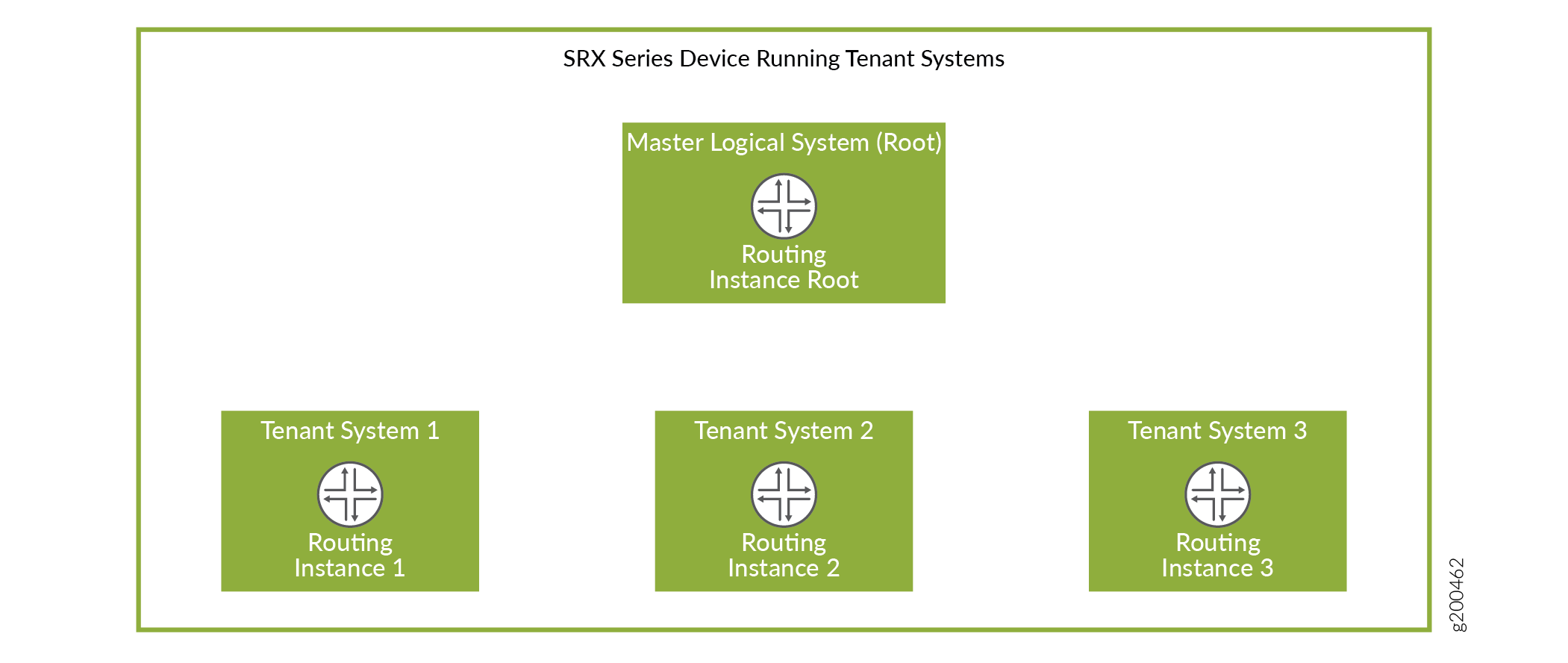
A tenant system logically partitions the physical firewall into separate and isolated logical firewall. Although similar to logical systems, tenant systems have much higher scalability and fewer routing features. Each tenant system on a device allows you to control a discrete administrative domain for security services. By transforming your device into a multitenant system, you can provide various departments, organizations, customers, and partners—depending on your environment—private and logically separated use of system resources and tenant-specific views of security configuration and KPIs. A primary administrator creates and manages all the tenant systems. Figure 1 shows a single device with a primary logical system and discrete tenant systems.
- Differences Between Logical Systems and Tenant Systems
- Use Cases for Logical Systems and Tenant Systems
- Deployment Scenarios for Multitenant Systems
- Benefits of Tenant Systems
- Roles and Responsibilities of Primary Administrator and Tenant System Administrator
Differences Between Logical Systems and Tenant Systems
Table 1 describes the key differences between logical systems and tenant systems.
|
Functionality |
Logical Systems |
Tenant Systems |
|---|---|---|
|
Feature support |
Supports all the routing features to provide optimal data routing paths. |
Supports routing features and high-scale security virtualization to isolate customer environments. |
|
Routing protocol process |
Every logical system needs an individual copy of the routing protocol process to logically separate the resources on a device. |
The primary logical system has a single routing protocol process, which is shared by the tenant systems. Routing instances supported by this single routing protocol process achieve the security resource separation on the firewall. |
|
Routing instance |
A default routing instance is automatically created for every logical system. |
The virtual-router configured in a tenant system is passed as the default routing-instance to
|
|
Logical interface configuration |
The primary administrator assigns the logical interfaces and the logical system administrator can configure the interface attributes. |
A tenant system administrator cannot configure the logical interfaces. The primary administrator assigns the logical interfaces to a tenant system. |
Use Cases for Logical Systems and Tenant Systems
A logical system is used when more than one virtual router is required. For example, you have multiple connections to the external network and they cannot co-exist in the same virtual router. Tenant systems are used when you need to separate departments, organization, or customers and each of them can be limited to one virtual router. The main difference between a logical system and a tenant system is that a logical system supports advanced routing functionality using multiple routing instances. In comparison, a tenant system supports only one routing instance, but supports the deployment of significantly more tenants per system.
Deployment Scenarios for Multitenant Systems
You can deploy a security device running a multitenant system in many environments such as a managed security service provider (MSSP), an enterprise network, or a branch office segment. Table 2 describes the various deployment scenarios and the roles played by the tenant systems in such scenarios.
|
Deployment Scenarios |
Roles of a Tenant System |
|---|---|
|
Managed security service provider (MSSP) |
|
|
Enterprise network |
|
|
Branch office segment |
|
Benefits of Tenant Systems
-
Curtail cost by reducing the number of physical devices required for your organization. You can consolidate services for various groups of users on a single device and reduce the hardware costs, power expenditure, and rack space.
-
Provide isolation and logical separation at the tenant system level. Provides the ability to separate tenant systems with administrative separation at large scale in which each tenant system can define its own security controls and restrictions without impacting other tenant systems.
Roles and Responsibilities of Primary Administrator and Tenant System Administrator
A primary administrator creates and manages all the tenant systems. A primary logical system is created at the root level and is allocated a single routing protocol process. Although this routing protocol process is shared, tenant systems enable logical resource separation on the firewall. By default, all system resources are assigned to the primary logical system, and the primary administrator allocates them to the tenant system administrators.
In Junos OS command-line reference, primary logical system is referred as root logical system.
A tenant system is created that is subtended by the primary logical system. Although all the tenants under the primary logical system share a single routing process, each tenant system has a single routing instance. Table 3 describes the roles and responsibilities of the primary administrator and tenant system administrator.
|
Roles |
Definition |
Responsibilities |
|---|---|---|
|
Primary administrator |
A user account with superuser configuration and verification privileges for all logical systems and tenant systems. |
|
|
Tenant system administrator |
A tenant system account with all configuration and verification privileges. Note:
The configuration and verification privileges of a tenant system administrator depends on the permission assigned to them by the primary administrator while creating the tenant system administrator. Multiple tenant system administrators can be created for a tenant system with different permission levels based on your requirement. |
The following privileges are not supported by the tenant system administrator:
|
See Also
Tenant System Configuration Overview
The primary administrator creates a tenant system and assigns an administrator for managing the tenant system. A tenant system can have multiple administrators. The roles and responsibilities of a tenant system administrator are explained in Understanding Tenant Systems.
The primary administrator configures the logical interfaces and assigns those interfaces to the tenant system. Configure one routing instance and the routing protocols, and add options for the routing instance. See Configuring a Routing Instance for a Tenant System.
Tenant systems have their own configuration database. After successful configuration, the changes are merged to the primary database for each tenant systems. Multiple tenant systems can perform configuration changes at a time. You can commit the changes for only one tenant at a time. If the primary administrator and a tenant system administrator performs configuration changes simultaneously, the configuration changes performed by the primary administrator override the configuration changes performed by the tenant system administrator.
The following steps explain the tasks that the tenant system administrator performs to configure the security features in a tenant system:
Configuring a Routing Instance for a Tenant System
A routing instance is a collection of routing tables, interfaces, and routing protocol parameters. A set of interfaces that belong to the routing instance and the routing protocol parameters control the information in the routing instance. A tenant system can configure the assigned routing instance and the interfaces that belong to the routing instance within a tenant system.
Only one routing instance can be created for a tenant system.
The following procedure describes the steps to configure a routing instance and interfaces in a routing table for a tenant system:
To view the configuration for the tenant system TSYS1, run the show tenants TSYS1 command.
routing-instances {
r1 {
instance-type virtual-router;
interface lt-0/0/0.101;
interface xe-0/0/0.0;
interface xe-0/0/1.0;
routing-options {
router-id 1.1.1.101;
}
}
}
The show tenants TSYS1 command displays all the routing
instance parameters configured for the tenant system TSYS1.
Understanding Routing and Interfaces for Tenant Systems
A routing instance is a collection of routing tables, interfaces, and routing protocol parameters. The interfaces are used for forwarding data for the routing instance, and to learn the routing information from other peers ( security devices) using routing protocols.
A Logical interface (IFL) can be defined at either one of the following levels:
Global level (root logical system)
User logical system level
Tenant system level (Starting from Release Junos OS 18.4R1)
The IFL defined at the global level can be used either in root logical system or in one of the tenant systems. The IFL defined in a tenant system can be used in that tenant system only.
Default routing instance is not available for tenant systems. So, when a custom routing instance is created for a tenant system, all the interfaces defined in that tenant system should be added to that routing instance.
Overview: Configuring Routing and Interfaces for Tenant Systems
This overview shows how to configure interfaces and routing instances for a tenant system.
Requirements
Before you begin:
Determine which logical interfaces and, optionally, which logical tunnel interfaces are allocated. See Tenant System Configuration Overview.
Overview
The following procedure describes the steps to configure a routing instance and interfaces in a routing table within a tenant system.
This topic configures the interfaces and routing instances described in Table 4.
Feature |
Name |
Configuration Parameters |
|---|---|---|
Interface |
ge-0/0/2.1 ge-0/0/2.2 ge-0/0/2.3 |
|
Routing instance |
r1 r2 |
|
Configuration
Procedure
CLI Quick Configuration
To quickly configure this example, copy the
following commands, paste them into a text file, remove any line breaks,
change any details necessary to match your network configuration,
copy and paste the commands into the CLI at the [edit] hierarchy
level, and then enter commit from configuration mode.
set interfaces ge-0/0/2 vlan-tagging set interfaces ge-0/0/2.3 vlan-id 103 set interfaces ge-0/0/2.3 family inet address 10.0.0.3/24 set tenants TSYS1 set tenants TSYS1 interfaces ge-0/0/2.1 vlan-id 101 set tenants TSYS1 interfaces ge-0/0/2.1 family inet address 10.0.0.1/24 set tenants TSYS1 routing-instances r1 instance-type virtual-router set tenants TSYS1 routing-instances r1 interface ge-0/0/2.1 set tenants TSYS1 routing-instances r1 interface ge-0/0/2.3 set tenants TSYS2 set tenants TSYS2 interfaces ge-0/0/2.2 vlan-id 102 set tenants TSYS2 interfaces ge-0/0/2.2 family inet address 10.0.0.2/24 set tenants TSYS2 routing-instances r2 instance-type virtual-router set tenants TSYS2 routing-instances r2 interface ge-0/0/2.2
Step-by-Step Procedure
The following example requires you to navigate various levels in the configuration hierarchy. For instructions on how to do that, see Using the CLI Editor in Configuration Mode in the Junos OS CLI User Guide.
To configure an interface and a routing instance in a user logical system:
Configure the interfaces to support VLAN tagging.
[edit] user@host# set interfaces ge-0/0/2 vlan-tagging
Configure the IFL at the root level.
[edit] set interfaces ge-0/0/2.3 vlan-id 103 set interfaces ge-0/0/2.3 family inet address 10.0.0.3/24
Create a tenant system named
TSYS1.[edit] user@host# set tenants TSYS1
Define the Interface in the tenant system TSYS1.
[edit] user@host# set tenants TSYS1 interfaces ge-0/0/2.1 vlan-id 101 user@host# set tenants TSYS1 interfaces ge-0/0/2.1 family inet address 10.0.0.1/24 user@host# set tenants TSYS1 routing-instances r1 interface ge-0/0/2.3
Create a routing instance
r1and assign the routing instance type for the tenant system.[edit] user@host# set tenants TSYS1 routing-instances r1 instance-type virtual-router
Specify the interface name for the routing instance.
[edit] user@host# set tenants TSYS1 routing-instances r1 interface ge-0/0/2.1
Create a tenant system named
TSYS2.[edit] user@host# set tenants TSYS2
Define the Interface in the tenant system TSYS2.
[edit] user@host# set tenants TSYS2 interfaces ge-0/0/2.2 vlan-id 102 user@host# set tenants TSYS2 interfaces ge-0/0/2.2 family inet address 10.0.0.2/24
Create a routing instance
r2and assign the routing instance type for the tenant system.[edit] user@host# set tenants TSYS2 routing-instances r2 instance-type virtual-router
Specify the interface name for the routing instance.
[edit] user@host# set tenants TSYS2 routing-instances r2 interface ge-0/0/2.2
Commit the configuration.
[edit]
user@host# commit
Results
From configuration mode, confirm your configuration
by entering the show interfaces and show tenants commands. If the output does not display the intended configuration,
repeat the configuration instructions in this example to correct it.
[edit]
user@host# show interfaces
ge-0/0/2 {
    vlan-tagging;
    unit 3 {
        vlan-id 103;
        family inet {
            address 10.0.0.3/24;
        }
    }
}
[edit]
user@host# show tenants
TSYS1 {
    interfaces {
        ge-0/0/2 {
            unit 1 {
                vlan-id 101;
                family inet {
                    address 10.0.0.1/24;
                }
            }
        }
    }
    routing-instances {
        r1 {
            instance-type virtual-router;
            interface ge-0/0/2.1;
            interface ge-0/0/2.3;
        }
    }
}
TSYS2 {
    interfaces {
        ge-0/0/2 {
            unit 2 {
                vlan-id 102;
                family inet {
                    address 10.0.0.2/24;
                }
            }
        }
    }
    routing-instances {
        r2 {
            instance-type virtual-router;
            interface ge-0/0/2.2;
        }
    }
}
The show tenants command displays all the interfaces
that are defined in the tenant systems TSYS1 and TSYS2, and the routing instance parameters configured for both the tenant
systems.
user@host> show interfaces ge-0/0/2.1 detail
  Logical interface ge-0/0/2.1 (Index 89) (SNMP ifIndex 548) (Generation 161)
    Flags: Up SNMP-Traps 0x4000 VLAN-Tag [ 0x8100.101 ]  Encapsulation: ENET2
    Tenant Name: TSYS1
    Traffic statistics:
     Input  bytes  :                    0
     Output bytes  :                   46
     Input  packets:                    0
     Output packets:                    1
    Local statistics:
     Input  bytes  :                    0
     Output bytes  :                   46
     Input  packets:                    0
     Output packets:                    1
    Transit statistics:
     Input  bytes  :                    0                    0 bps
     Output bytes  :                    0                    0 bps
     Input  packets:                    0                    0 pps
     Output packets:                    0                    0 pps
    Security: Zone: Null
    Flow Statistics :
..............................user@host> show interfaces ge-0/0/2.2 detail
Logical interface ge-0/0/2.2 (Index 90) (SNMP ifIndex 549) (Generation 162)
Flags: Up SNMP-Traps 0x4000 VLAN-Tag [ 0x8100.102 ] Encapsulation: ENET2
Tenant Name: TSYS2
Traffic statistics:
Input bytes : 0
Output bytes : 46
Input packets: 0
Output packets: 1
Local statistics:
Input bytes : 0
Output bytes : 46
Input packets: 0
Output packets: 1
Transit statistics:
Input bytes : 0 0 bps
Output bytes : 0 0 bps
Input packets: 0 0 pps
Output packets: 0 0 pps
Security: Zone: Null
Flow Statistics :
Flow Input statistics :
Self packets : 0
ICMP packets : 0
VPN packets : ..............................Understanding Tenant System Security Profiles (Primary Administrators Only)
Tenant systems allow you to virtually divide a supported security devices into multiple devices, securing them from intrusion and attacks, and protecting them from faulty conditions outside their own contexts. To protect tenant systems, security resources are configured in a manner similar to how they are configured for a discrete device. However, the primary administrator assigns resources to the tenant systems.
A security device running tenant systems can be partitioned into tenant systems, an interconnected tenant system, if necessary, and the default primary logical system. When the system is initialized, the primary logical system is created at the root. All system resources are assigned to it, effectively creating a default primary logical system security profile. To distribute security resources across the tenant systems, the primary administrator creates security profiles that specify the resources to be allocated to a tenant system. Only the primary administrator can configure security profiles and bind them to the tenant systems. The tenant system administrator uses these resources for the respective tenant system.
The tenant systems are defined by the resources allocated to them, including security components, interfaces, routing instance, static routes, and dynamic routing protocols. The primary administrator configures the security profiles and assigns them to the tenant systems. You cannot commit a tenant system configuration without a security profile assigned to it.
This topic includes the following sections:
- Tenant Systems Security Profiles
- Understanding How the System Assesses Resources Assignment and Use Across the Tenant Systems
- Cases: Assessments of Reserved Resources Assigned Through Security Profiles
Tenant Systems Security Profiles
The primary administrator can configure and assign a security profile to a specific tenant system or multiple tenant systems. The maximum number of security profiles that can be configured depends on the capacity of a security device. When the maximum number of security profiles have been created, you need to delete a security profile and commit the configuration change before you can create and commit another security profile. In many cases, fewer security profiles are needed because you can bind a single security profile to more than one tenant system.
Security profiles allow you to:
Share the device’s resources, including policies, zones, addresses and address books, flow sessions, and various forms of NAT, among all tenant systems appropriately. You can assign various amounts of a resource to the tenant systems and allow the tenant systems to utilize the resources effectively.
Security profiles protect against one tenant system exhausting a resource that is required at the same time by other tenant systems. Security profiles protect critical system resources and maintain a better performance among tenant systems when the device is experiencing a heavy traffic flow. Security profiles defend against one tenant system dominating the use of resources and allow the other tenant systems to use the resources effectively.
Configure the device in a scalable way to allow for creation of additional tenant systems.
You need to delete the security profile of a tenant system before you can delete the tenant system.
Understanding How the System Assesses Resources Assignment and Use Across the Tenant Systems
To provision a tenant system with security features, the primary administrator configures a security profile that specifies the resource for each security feature:
A reserved quota that guarantees that the specified resource amount is always available to the tenant system.
A maximum allowed quota. If a tenant system requires additional resources that exceed the reserved quota, then it can utilize the resources configured for the global maximum amount if the global resources are not allocated to the other tenant systems. The maximum allowed quota does not guarantee that the amount specified for the resource in the security profile is available. The tenant systems need to utilize the global resources effectively based on the available resources.
If a reserved quota is not configured for a resource, the default value is 0. If a maximum allowed quota is not configured for a resource, the default value is the global system quota for the resource (global system quotas are platform-dependent). The primary administrator must configure the appropriate maximum allowed quota values in the security profiles so that the maximum resource usage of a specific tenant system does not negatively impact other tenant systems configured on the device.
The system maintains a count of all allocated resources that are reserved, used, and made available again when a tenant system is deleted. This count determines whether resources are available to use for tenant systems or to increase the amount of the resources allocated to existing tenant systems through their security profiles.
Resources configured in security profiles are characterized as static modular resources or dynamic resources. For static resources, we recommend setting a maximum quota for a resource equal or close to the amount specified as its reserved quota, to allow for scalable configuration of tenant systems. A maximum quota for a resource gives a tenant system greater flexibility through access to a larger amount of that resource, but it constrains the amount of resources available to allocate to other tenant systems.
The following security features resources can be specified in a security profile:
Security zones
Addresses and address books for security policies
Application firewall rule sets
Application firewall rules
Firewall authentication
Flow sessions and gates
NAT, including:
Cone NAT bindings
NAT destination rule
NAT destination pool
NAT IP address in source pool without Port Address Translation (PAT)
Note:IPv6 addresses in IPv6 source pools without PAT are not included in security profiles.
NAT IP address in source pool with PAT
NAT port overloading
NAT source pool
NAT source rule
NAT static rule
All resources except flow sessions are static.
You can modify a tenant system security profile dynamically while the security profile is assigned to other tenant systems. However, to ensure that the system resource quota is not exceeded, the system takes the following actions:
If a static quota is changed, the system process that maintains the tenant system counts for resources specified in security profiles subsequently reevaluates the security profiles assigned to the profile associated with the static quota. This check identifies the number of resources assigned across all tenant systems to determine whether the allocated resources, including their increased amounts are available.
These quota checks are the same quota checks that the system performs when you add a tenant system and bind a security profile to it. They are also performed when you bind a different security profile from the security profile that is currently assigned to it to an existing tenant system (or the primary logical system).
If a dynamic quota is revised, no check is performed, but the revised quota is imposed on future resource usage.
Cases: Assessments of Reserved Resources Assigned Through Security Profiles
To understand how the system assesses allocation of reserved resources through security profiles, consider the following three cases explained in Table 6 and that address allocation of the resources and zones. To keep the example simple, 10 zones are allocated in security-profile-1: 4 reserved zones and 6 maximum zones. This example assumes that the maximum amount specified—six zones—is available for the tenant systems. The system maximum number of zones is 10.
The three cases address the configuration across the tenant systems. The three cases verify whether a configuration succeeds or fails when it is committed based on the allocation of zones.
Table 5 shows the security profiles and their zone allocations.
Two Security Profiles Used in the Configuration Cases |
|---|
security-profile-1
Note:
The primary administrator dynamically increases the reserved zone count specified in this profile later. |
primary-logical-system-profile
|
Table 6 shows three cases that illustrate how the system assesses reserved resources for zones across the tenant systems based on the security profile configurations.
The configuration for the first case succeeds because the cumulative reserved resource quota for zones configured in the security profiles bound to all tenant systems is 8, which is less than the system maximum resource quota.
The configuration for the second case fails because the cumulative reserved resource quota for zones configured in the security profiles bound to all logical systems is 12, which is greater than the system maximum resource quota.
The configuration for the third case fails because the cumulative reserved resource quota for zones configured in the security profiles bound to all tenant systems is 12, which is greater than the system maximum resource quota.
Reserved Resource Quota Checks Across Tenant Systems |
|---|
Example 1: Succeeds This configuration is within bounds: 4+4+0=8, maximum capacity =10. Security Profiles Used
|
Example 2: Fails This configuration is out of bounds: 4+4+4=12, maximum capacity =10.
Security Profiles
|
Example 3: Fails This configuration is out of bounds: 6+6=12, maximum capacity =10. The primary administrator modifies the reserved zones quota in security-profile-1, increasing the count to 6.
|
Example: Creating Tenant Systems, Tenant System Administrators, and an Interconnect VPLS Switch
This example shows how to create tenant systems, tenant system administrators, and an interconnect VPLS switch. Only the primary administrator can create user login accounts for tenant system administrators and interconnect VPLS switch.
Requirements
This example uses the following hardware and software components:
-
Any supported firewall.
-
Junos OS Release 18.4R1 and later releases.
-
Before you begin creating the tenant systems, tenant system administrators, and an interconnect VPLS switch, read Tenant Systems Overview to understand how this task fits into the overall configuration process.
Overview
This example shows how to create the tenant systems TSYS1,
TSYS2, and TSYS3, and the tenant system
administrators for them. You can create multiple tenant system administrators for a
tenant system with different permission levels based on your requirements.
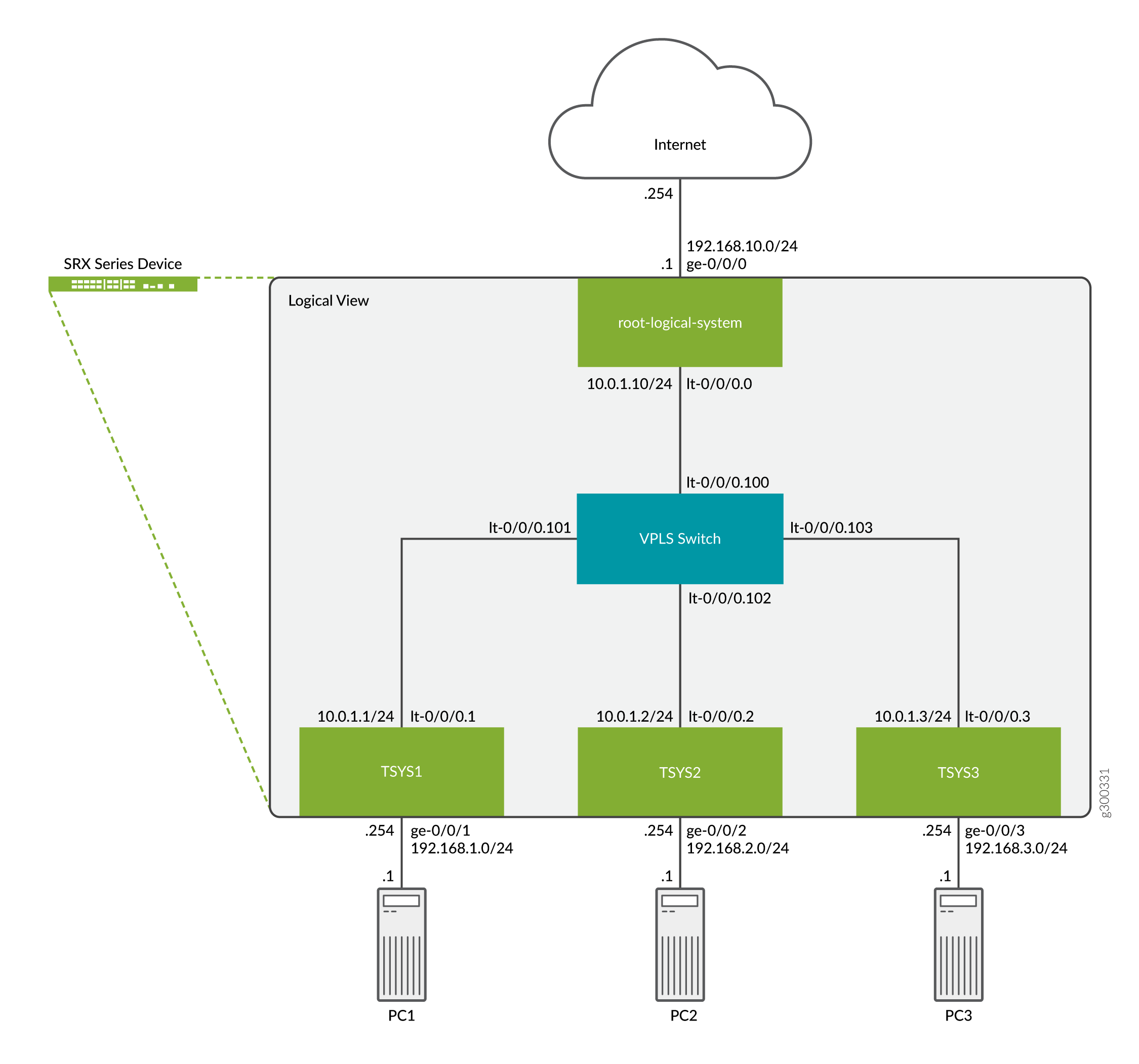
This topic also covers the interconnect virtual private LAN service (VPLS) switch connecting one tenant system to another on the same device. The VPLS switch enables both transit traffic and traffic terminated at a tenant system to pass between tenant systems. To allow traffic to pass between tenant systems, logical tunnel (lt-0/0/0) interfaces should be configured in the same subnet.
Topology
The Figure 2 shows asecurity device deployed and configured for tenant systems. The configuration example uses static routing to allow the PCs to reach the Internet.
Quick Configuration
Configuring Logical and Tenant Systems, and Interconnect VPLS Switch
CLI Quick Configuration
To quickly configure this example, copy the following commands, paste them
into a text file, remove any line breaks, and change any details necessary
to match your network configuration to include interfaces and user
passwords. Then copy and paste the commands into the CLI at the
[edit] hierarchy level, and enter
commit from configuration mode.
set system login class TSYS1admin1 tenant TSYS1
set system login class TSYS1admin1 permissions all
set system login class TSYS2admin1 tenant TSYS2
set system login class TSYS2admin1 permissions all
set system login class TSYS3admin1 tenant TSYS3
set system login class TSYS3admin1 permissions all
set system login user TSYS1admin1 uid 2001
set system login user TSYS1admin1 class TSYS1admin1
set system login user TSYS1admin1 authentication encrypted-password "$ABC123"
set system login user TSYS2admin1 uid 2003
set system login user TSYS2admin1 class TSYS2admin1
set system login user TSYS2admin1 authentication encrypted-password "$ABC123"
set system login user TSYS3admin1 uid 2005
set system login user TSYS3admin1 class TSYS3admin1
set system login user TSYS3admin1 authentication encrypted-password "$ABC123"
set system security-profile SP0 logical-system root-ls
set system security-profile SP1 tenant TSYS1
set system security-profile SP2 tenant TSYS2
set system security-profile SP3 tenant TSYS3
set logical-systems root-ls interfaces ge-0/0/0 unit 0 family inet address 192.168.10.1/24
set logical-systems root-ls interfaces lt-0/0/0 unit 0 encapsulation ethernet
set logical-systems root-ls interfaces lt-0/0/0 unit 0 peer-unit 100
set logical-systems root-ls interfaces lt-0/0/0 unit 0 family inet address 10.0.1.10/24
set logical-systems root-ls routing-options static route 192.168.1.0/24 next-hop 10.0.1.1
set logical-systems root-ls routing-options static route 192.168.2.0/24 next-hop 10.0.1.2
set logical-systems root-ls routing-options static route 192.168.3.0/24 next-hop 10.0.1.3
set logical-systems root-ls security address-book global address TSYS1 192.168.1.0/24
set logical-systems root-ls security address-book global address TSYS2 192.168.2.0/24
set logical-systems root-ls security address-book global address TSYS3 192.168.3.0/24
set logical-systems root-ls security policies from-zone trust to-zone untrust policy allow-out match source-address TSYS1
set logical-systems root-ls security policies from-zone trust to-zone untrust policy allow-out match source-address TSYS2
set logical-systems root-ls security policies from-zone trust to-zone untrust policy allow-out match source-address TSYS3
set logical-systems root-ls security policies from-zone trust to-zone untrust policy allow-out match destination-address any
set logical-systems root-ls security policies from-zone trust to-zone untrust policy allow-out match application any
set logical-systems root-ls security policies from-zone trust to-zone untrust policy allow-out then permit
set logical-systems root-ls security zones security-zone trust host-inbound-traffic system-services ping
set logical-systems root-ls security zones security-zone trust interfaces lt-0/0/0.0
set logical-systems root-ls security zones security-zone untrust host-inbound-traffic system-services ping
set logical-systems root-ls security zones security-zone untrust interfaces ge-0/0/0.0
set interfaces lt-0/0/0 unit 1 encapsulation ethernet
set interfaces lt-0/0/0 unit 1 peer-unit 101
set interfaces lt-0/0/0 unit 1 family inet address 10.0.1.1/24
set interfaces lt-0/0/0 unit 2 encapsulation ethernet
set interfaces lt-0/0/0 unit 2 peer-unit 102
set interfaces lt-0/0/0 unit 2 family inet address 10.0.1.2/24
set interfaces lt-0/0/0 unit 3 encapsulation ethernet
set interfaces lt-0/0/0 unit 3 peer-unit 103
set interfaces lt-0/0/0 unit 3 family inet address 10.0.1.3/24
set interfaces lt-0/0/0 unit 100 encapsulation ethernet-vpls
set interfaces lt-0/0/0 unit 100 peer-unit 0
set interfaces lt-0/0/0 unit 101 encapsulation ethernet-vpls
set interfaces lt-0/0/0 unit 101 peer-unit 1
set interfaces lt-0/0/0 unit 102 encapsulation ethernet-vpls
set interfaces lt-0/0/0 unit 102 peer-unit 2
set interfaces lt-0/0/0 unit 103 encapsulation ethernet-vpls
set interfaces lt-0/0/0 unit 103 peer-unit 3
set interfaces ge-0/0/1 unit 0 family inet address 192.168.1.254/24
set interfaces ge-0/0/2 unit 0 family inet address 192.168.2.254/24
set interfaces ge-0/0/3 unit 0 family inet address 192.168.3.254/24
set routing-instances VPLS instance-type vpls
set routing-instances VPLS interface lt-0/0/0.100
set routing-instances VPLS interface lt-0/0/0.101
set routing-instances VPLS interface lt-0/0/0.102
set routing-instances VPLS interface lt-0/0/0.103
set tenants TSYS1 routing-instances vr1 instance-type virtual-router
set tenants TSYS1 routing-instances vr1 routing-options static route 0.0.0.0/0 next-hop 10.0.1.10
set tenants TSYS1 routing-instances vr1 interface lt-0/0/0.1
set tenants TSYS1 routing-instances vr1 interface ge-0/0/1.0
set tenants TSYS1 security address-book global address PC1 192.168.1.0/24
set tenants TSYS1 security policies from-zone PC1 to-zone VPLS policy allow-out match source-address PC1
set tenants TSYS1 security policies from-zone PC1 to-zone VPLS policy allow-out match destination-address any
set tenants TSYS1 security policies from-zone PC1 to-zone VPLS policy allow-out match application any
set tenants TSYS1 security policies from-zone PC1 to-zone VPLS policy allow-out then permit
set tenants TSYS1 security zones security-zone PC1 host-inbound-traffic system-services ping
set tenants TSYS1 security zones security-zone PC1 interfaces ge-0/0/1.0
set tenants TSYS1 security zones security-zone VPLS host-inbound-traffic system-services ping
set tenants TSYS1 security zones security-zone VPLS interfaces lt-0/0/0.1
set tenants TSYS2 routing-instances vr2 instance-type virtual-router
set tenants TSYS2 routing-instances vr2 routing-options static route 0.0.0.0/0 next-hop 10.0.1.10
set tenants TSYS2 routing-instances vr2 interface lt-0/0/0.2
set tenants TSYS2 routing-instances vr2 interface ge-0/0/2.0
set tenants TSYS2 security address-book global address PC2 192.168.2.0/24
set tenants TSYS2 security policies from-zone PC2 to-zone VPLS policy allow-out match source-address PC2
set tenants TSYS2 security policies from-zone PC2 to-zone VPLS policy allow-out match destination-address any
set tenants TSYS2 security policies from-zone PC2 to-zone VPLS policy allow-out match application any
set tenants TSYS2 security policies from-zone PC2 to-zone VPLS policy allow-out then permit
set tenants TSYS2 security zones security-zone PC2 host-inbound-traffic system-services ping
set tenants TSYS2 security zones security-zone PC2 interfaces ge-0/0/2.0
set tenants TSYS2 security zones security-zone VPLS host-inbound-traffic system-services ping
set tenants TSYS2 security zones security-zone VPLS interfaces lt-0/0/0.2
set tenants TSYS3 routing-instances vr3 instance-type virtual-router
set tenants TSYS3 routing-instances vr3 routing-options static route 0.0.0.0/0 next-hop 10.0.1.10
set tenants TSYS3 routing-instances vr3 interface lt-0/0/0.3
set tenants TSYS3 routing-instances vr3 interface ge-0/0/3.0
set tenants TSYS3 security address-book global address PC3 192.168.3.0/24
set tenants TSYS3 security policies from-zone PC3 to-zone VPLS policy allow-out match source-address PC3
set tenants TSYS3 security policies from-zone PC3 to-zone VPLS policy allow-out match destination-address any
set tenants TSYS3 security policies from-zone PC3 to-zone VPLS policy allow-out match application any
set tenants TSYS3 security policies from-zone PC3 to-zone VPLS policy allow-out then permit
set tenants TSYS3 security zones security-zone PC3 host-inbound-traffic system-services ping
set tenants TSYS3 security zones security-zone PC3 interfaces ge-0/0/3.0
set tenants TSYS3 security zones security-zone VPLS host-inbound-traffic system-services ping
set tenants TSYS3 security zones security-zone VPLS interfaces lt-0/0/0.3
Step-by-Step Procedure
The following example requires you to navigate various levels in the configuration hierarchy. For instructions on how to do that, see Using the CLI Editor in Configuration Mode in the CLI User Guide. We will only be covering the configuration of one tenant for the step-by-step procedure.
-
Create the login user accounts for each tenant. We will only show the steps for creating the tenant
TSYS1user account.-
Create the user login class and assign it to the tenant system.
[edit]
user@SRX# set system login class TSYS1admin1 tenant TSYS1
-
Assign a permissions level to the login class, for this example we will use the level
allwhich allows full access to the tenant system administrator.[edit] user@SRX# set system login class TSYS1admin1 permissions all
-
Create a user account and assign it to the class from the previous steps. This will allow the user to login to the tenant system.
[edit]
user@SRX# set system login user TSYS1admin1 class TSYS1admin1
-
Create a user login password for the user account.
[edit]
user@SRX# set system login user TSYS1admin1 authentication plain-text-password
New password: "$ABC123"
Retype new password: "$ABC123"
-
-
Configure the VPLS switch. The VPLS switch enables both transit traffic and traffic terminated at a tenant system to pass between tenant systems with a single logical tunnel. Logical tunnel interfaces should be configured in the same subnet to allow traffic between tenant systems.
-
Configure the logical tunnel interfaces.
[edit]
user@SRX# set interfaces lt-0/0/0 unit 100 encapsulation ethernet-vpls
user@SRX# set interfaces lt-0/0/0 unit 100 peer-unit 0
user@SRX# set interfaces lt-0/0/0 unit 101 encapsulation ethernet-vpls
user@SRX# set interfaces lt-0/0/0 unit 101 peer-unit 1
user@SRX# set interfaces lt-0/0/0 unit 102 encapsulation ethernet-vpls
user@SRX# set interfaces lt-0/0/0 unit 102 peer-unit 2
user@SRX# set interfaces lt-0/0/0 unit 103 encapsulation ethernet-vpls
user@SRX# set interfaces lt-0/0/0 unit 103 peer-unit 3
-
Configure a routing instance for the VPLS switch and assign the logical tunnel interfaces.
[edit]
user@SRX# set routing-instances VPLS instance-type vpls
user@SRX# set routing-instances VPLS interface lt-0/0/0.100
user@SRX# set routing-instances VPLS interface lt-0/0/0.101
user@SRX# set routing-instances VPLS interface lt-0/0/0.102
user@SRX# set routing-instances VPLS interface lt-0/0/0.103
-
-
Configure the tenant systems. We are only showing the configuration for one tenant.
-
Configure the interfaces associated with the tenant.
[edit]
user@SRX# set interfaces lt-0/0/0 unit 1 encapsulation ethernet
user@SRX# set interfaces lt-0/0/0 unit 1 peer-unit 101
user@SRX# set interfaces lt-0/0/0 unit 1 family inet address 10.0.1.1/24
user@SRX# set interfaces ge-0/0/1 unit 0 family inet address 192.168.1.254/24
-
Configure the tenant, routing instance, static routing and assign the interfaces.
[edit]
user@SRX# set tenants TSYS1 routing-instances vr1 instance-type virtual-router
user@SRX# set tenants TSYS1 routing-instances vr1 routing-options static route 0.0.0.0/0 next-hop 10.0.1.10
user@SRX# set tenants TSYS1 routing-instances vr1 interface lt-0/0/0.1
user@SRX# set tenants TSYS1 routing-instances vr1 interface ge-0/0/1.0
-
-
Configure the security profiles. We are only showing the minimal configuration needed to configure logical and tenant systems for this example.
[edit]
user@SRX# set system security-profile SP0 logical-system root-ls
user@SRX# set system security-profile SP1 tenant TSYS1
user@SRX# set system security-profile SP2 tenant TSYS2
user@SRX# set system security-profile SP3 tenant TSYS3
-
Configure the logical systems. This example using an interconnect VPLS switch requires a logical systems.
-
Configure the interfaces.
[edit]
user@SRX# set logical-systems root-ls interfaces ge-0/0/0 unit 0 family inet address 192.168.10.1/24
user@SRX# set logical-systems root-ls interfaces lt-0/0/0 unit 0 encapsulation ethernet
user@SRX# set logical-systems root-ls interfaces lt-0/0/0 unit 0 peer-unit 100
user@SRX# set logical-systems root-ls interfaces lt-0/0/0 unit 0 family inet address 10.0.1.10/24
-
Configure the static routes.
[edit]
user@SRX# set logical-systems root-ls routing-options static route 192.168.1.0/24 next-hop 10.0.1.1
user@SRX# set logical-systems root-ls routing-options static route 192.168.2.0/24 next-hop 10.0.1.2
user@SRX# set logical-systems root-ls routing-options static route 192.168.3.0/24 next-hop 10.0.1.3
-
-
Configure security zones and policies in the logical systems to allow traffic flow from the tenants to the Internet. Additional security policies can be configured on both the logical and tenant systems to allow traffic between tenants.
-
Configure security zones.
[edit]
user@SRX# set logical-systems root-ls security zones security-zone trust host-inbound-traffic system-services ping
user@SRX# set logical-systems root-ls security zones security-zone trust interfaces lt-0/0/0.0
user@SRX# set logical-systems root-ls security zones security-zone untrust host-inbound-traffic system-services ping
user@SRX# set logical-systems root-ls security zones security-zone untrust interfaces ge-0/0/0.0
-
Configure security policies.
[edit]
user@SRX# set logical-systems root-ls security address-book global address TSYS1 192.168.1.0/24
user@SRX# set logical-systems root-ls security address-book global address TSYS2 192.168.2.0/24
user@SRX# set logical-systems root-ls security address-book global address TSYS3 192.168.3.0/24
user@SRX# set logical-systems root-ls security policies from-zone trust to-zone untrust policy allow-out match source-address TSYS1
user@SRX# set logical-systems root-ls security policies from-zone trust to-zone untrust policy allow-out match source-address TSYS2
user@SRX# set logical-systems root-ls security policies from-zone trust to-zone untrust policy allow-out match source-address TSYS3
user@SRX# set logical-systems root-ls security policies from-zone trust to-zone untrust policy allow-out match destination-address any
user@SRX# set logical-systems root-ls security policies from-zone trust to-zone untrust policy allow-out match application any
user@SRX# set logical-systems root-ls security policies from-zone trust to-zone untrust policy allow-out then permit
-
-
Configure security zones and policies in each tenant systems to allow traffic flow to the Internet.
-
Configure security zones.
[edit]
user@SRX# set tenants TSYS1 security zones security-zone PC1 host-inbound-traffic system-services ping
user@SRX# set tenants TSYS1 security zones security-zone PC1 interfaces ge-0/0/1.0
user@SRX# set tenants TSYS1 security zones security-zone VPLS host-inbound-traffic system-services ping
user@SRX# set tenants TSYS1 security zones security-zone VPLS interfaces lt-0/0/0.1
-
Configure security policies.
[edit]
user@SRX# set tenants TSYS1 security address-book global address PC1 192.168.1.0/24
user@SRX# set tenants TSYS1 security policies from-zone PC1 to-zone VPLS policy allow-out match source-address PC1
user@SRX# set tenants TSYS1 security policies from-zone PC1 to-zone VPLS policy allow-out match destination-address any
user@SRX# set tenants TSYS1 security policies from-zone PC1 to-zone VPLS policy allow-out match application any
user@SRX# set tenants TSYS1 security policies from-zone PC1 to-zone VPLS policy allow-out then permit
-
Results
From configuration mode, confirm your configuration by entering the
show tenants TSYS1 command to verify that the tenant
system is created. Enter the show system login class
TSYS1admin1 command to view the permission level for each class
that you defined. To ensure that the tenant system administrators are
created, enter the show system login user TSYS1admin1
command. To ensure that the interfaces for interconnect VPLS switch are
created, enter the show interfaces command. Enter
show logical-systems to verify the root logical systems
configuration.
user@SRX# show tenants TSYS1
routing-instances {
    vr1 {
        instance-type virtual-router;
        routing-options {
            static {
                route 0.0.0.0/0 next-hop 10.0.1.10;
            }
        }
        interface lt-0/0/0.1;
        interface ge-0/0/1.0;
    }
}
security {
    address-book {
        global {
            address PC1 192.168.1.0/24;
        }
    }
    policies {
        from-zone PC1 to-zone VPLS {
            policy allow-out {
                match {
                    source-address PC1;
                    destination-address any;
                    application any;
                }
                then {
                    permit;
                }
            }
        }
    }
    zones {
        security-zone PC1 {
            host-inbound-traffic {
                system-services {
                    ping;
                }
            }
            interfaces {
                ge-0/0/1.0;
            }
        }
        security-zone VPLS {
            host-inbound-traffic {
                system-services {
                    ping;
                }
            }
            interfaces {
                lt-0/0/0.1;
            }
        }
    }
}user@SRX# show system login class TSYS1admin1 tenant TSYS1; permissions all;
user@SRX# show system login user TSYS1admin1
uid 2001;
class TSYS1admin1;
authentication {
    encrypted-password "$ABC123";
}user@SRX# show interfaces
lt-0/0/0 {
unit 1 {
encapsulation ethernet;
peer-unit 101;
family inet {
address 10.0.1.1/24;
}
}
unit 2 {
encapsulation ethernet;
peer-unit 102;
family inet {
address 10.0.1.2/24;
}
}
unit 3 {
encapsulation ethernet;
peer-unit 103;
family inet {
address 10.0.1.3/24;
}
}
unit 100 {
encapsulation ethernet-vpls;
peer-unit 0;
}
unit 101 {
encapsulation ethernet-vpls;
peer-unit 1;
}
unit 102 {
encapsulation ethernet-vpls;
peer-unit 2;
}
unit 103 {
encapsulation ethernet-vpls;
peer-unit 3;
}
}
ge-0/0/1 {
unit 0 {
family inet {
address 192.168.1.254/24;
}
}
}
ge-0/0/2 {
unit 0 {
family inet {
address 192.168.2.254/24;
}
}
}
ge-0/0/3 {
unit 0 {
family inet {
address 192.168.3.254/24;
}
}
}user@SRX# show logical-systems
root-ls {
interfaces {
ge-0/0/0 {
unit 0 {
family inet {
address 192.168.10.1/24;
}
}
}
lt-0/0/0 {
unit 0 {
encapsulation ethernet;
peer-unit 100;
family inet {
address 10.0.1.10/24;
}
}
}
}
routing-options {
static {
route 192.168.1.0/24 next-hop 10.0.1.1;
route 192.168.2.0/24 next-hop 10.0.1.2;
route 192.168.3.0/24 next-hop 10.0.1.3;
}
}
security {
address-book {
global {
address TSYS1 192.168.1.0/24;
address TSYS2 192.168.2.0/24;
address TSYS3 192.168.3.0/24;
}
}
policies {
from-zone trust to-zone untrust {
policy allow-out {
match {
source-address [ TSYS1 TSYS2 TSYS3 ];
destination-address any;
application any;
}
then {
permit;
}
}
}
}
zones {
security-zone trust {
host-inbound-traffic {
system-services {
ping;
}
}
interfaces {
lt-0/0/0.0;
}
}
security-zone untrust {
host-inbound-traffic {
system-services {
ping;
}
}
interfaces {
ge-0/0/0.0;
}
}
}
}
}If the output does not display the intended configuration, repeat the
configuration instructions in these examples to correct it. If you are done
configuring the device, enter commit from configuration
mode.
Verification
Confirm that the configuration is working properly.
- Verifying Tenant Systems and Login Configurations Using Primary Administrator
- Verifying Tenant Systems and Login Configurations Using SSH
- Verifying PC1 Connectivity to the Internet
Verifying Tenant Systems and Login Configurations Using Primary Administrator
Purpose
Verify that the tenant systems exist and you can enter them from root as the primary administrator. Return from the tenant system to the root.
Action
From operational mode, use the following command to enter the tenant systems
TSYS1:
user@SRX> set cli tenant TSYS1
Tenant: TSYS1
user@SRX:TSYS1>
Now you are entered to the tenant systems TSYS1. Use the
following command to exit from tenant systems TSYS1 to the
root:
user@SRX:TSYS1> clear cli tenant
Cleared default tenants
user@SRX>
Meaning
Tenant system exists and you can enter to the tenant system from the root as the primary administrator.
Verifying Tenant Systems and Login Configurations Using SSH
Purpose
Verify that the tenant systems you created exist, and that the administrator login IDs and passwords that you created are correct.
Action
Use SSH to log in to each user tenant system administrator.
-
Run SSH specifying the IP address of your security device.
-
Enter the login ID and password for the tenant systems administrator that you created. After you log in, the prompt shows the tenant systems administrator name. Notice how this result differs from the result produced when you log in to the tenant system from the primary logical system at root. Repeat this procedure for all of your tenant systems.
login: TSYS1admin1
Password: "$ABC123"

TSYS1admin1@SRX: TSYS1>
Meaning
Tenant system administrator TSYS1admin1 exists and you can
login as the tenant system administrator.
Verifying PC1 Connectivity to the Internet
Purpose
Verify end-to-end connectivity.
Action
Ping and run traceroute to the Internet from PC1. In our example the Internet is 192.168.10.254.
-
Run ping from PC1.
user@PC1> ping 192.168.10.254 count 2
PING 192.168.10.254 (192.168.10.254): 56 data bytes
64 bytes from 192.168.10.254: icmp_seq=0 ttl=62 time=3.178 ms
64 bytes from 192.168.10.254: icmp_seq=1 ttl=62 time=3.082 ms

--- 192.168.10.254 ping statistics ---
2 packets transmitted, 2 packets received, 0% packet loss
round-trip min/avg/max/stddev = 3.082/3.130/3.178/0.048 ms
-
Run traceroute from PC1.
user@PC1> traceroute 192.168.10.254
traceroute to 192.168.10.254 (192.168.10.254), 30 hops max, 52 byte packets
 1  192.168.1.254 (192.168.1.254)  2.188 ms  1.779 ms  1.896 ms
 2  10.0.1.10 (10.0.1.10)  1.888 ms  1.535 ms  1.661 ms
 3  192.168.10.254 (192.168.10.254)  3.243 ms  15.077 ms  3.499 ms
Meaning
PC1 is able to reach the Internet.
Platform-Specific Logical System and Tenant System Behavior
Use Feature Explorer to confirm platform and release support for specific features.
See the Additional Platform Information section for more information.
Use the following table to review platform-specific behaviors for your platform:
|
Platform |
Difference |
|---|---|
|
SRX Series |
|
Additional Platform Information
Use Feature Explorer to confirm platform and release support for specific features. Additional platforms may be supported.
Review the Platform-Specific Logical System and Tenant System Behavior section for notes related to your platform.
| Capacity | SRX1500 | SRX1600 | SRX2300 SRX4100 SRX4120 SRX4300 | SRX4200 | SRX4600 SRX4700 | SRX5400 SRX5600 SRX5800 Firewalls with SPC2 cards | SRX5400 SRX5600 SRX5800 Firewalls with SPC3 cards | SRX5400 SRX5600 SRX5800 Firewalls with SPC2 and SPC3 cards | vSRX Virtual Firewalls |
|---|---|---|---|---|---|---|---|---|---|
|
Logical Systems Capacity |
27 |
32 |
32 |
27 |
32 |
32 |
32 |
32 |
8 |
| Tenant Systems Capacity |
50 |
50 | 200 | 200 | 300 | 100 | 500 | 100 | 42 |
Change History Table
Feature support is determined by the platform and release you are using. Use Feature Explorer to determine if a feature is supported on your platform.
ping, telnet, ssh,
traceroute, show arp, clear
arp, show ipv6 neighbors, and clear ipv6
neighbors commands.