Flow for Tenant Systems
This topic explains how packets are processed in flow sessions on devices that are configured with tenant systems. It describes how the device running tenant systems handles pass-through traffic between tenant systems. This topic also covers self-traffic as self-initiated traffic within a tenant system and self-traffic terminated on another tenant system. Before addressing tenant systems, the topic provides basic information about the security architecture with respect to packet processing and sessions. Finally, addresses the sessions and how to change session characteristics.
Session Creation for Devices Running Tenant Systems
A session is created, based on routing and other classification information, to store information and allocate resources for a flow. Basically, a session is established when a traffic enters a tenant system interface, route lookup is performed to identify the next hop interface, and policy lookup is performed.
Optionally, the tenant systems enable you to configure an internal software switch. A virtual private LAN switch (VPLS) is implemented as an interconnect in tenant system. The VPLS enables both transit traffic and traffic terminated at a tenant system to pass between tenant systems. To allow traffic to pass between tenant systems or between tenant system and logical system, logical tunnel (lt-0/0/0) interfaces across the interconnect tenant system are used.
Packet sequence occurs at the ingress and the egress interfaces. Packets traversing between tenant systems might not be processed in the order in which they were received on the physical interface.
- Understanding Packet Classification
- Understanding the VPLS Switch and Logical Tunnel Interfaces
- Handling Pass-Through Traffic for Tenant Systems
- Handling Self-Traffic
- Understanding Session and Gate Limitation Control
- About Configuring Sessions
Understanding Packet Classification
The Packet classification for a flow-based processing is based on both the physical interface and the logical interface and depends on the incoming interface. The packet classification is performed at the ingress point and within a flow, the packet-based processing also takes place on an SPU sometimes.
Packet classification is assessed the same way for devices that are configured with or without tenant systems. The traffic for a dedicated interface is classified to the tenant system that contains that interface. The filters and class-of-service features are typically associated with an interface to influence which packets are allowed to transit the device and to apply special actions to packets as needed.
Packet classification is similar for devices with or without tenant systems, but policers in tenant systems have limitations. Policers inside tenant systems may not register hits properly. To monitor hits, apply the policer to a root system interface. This issue only affects policer hit counters, not other filter or class-of-service features.
Understanding the VPLS Switch and Logical Tunnel Interfaces
This topic covers the interconnect tenant system that serves as an internal virtual private LAN service (VPLS) switch connecting one tenant system on the device to another. The topic also explains how logical tunnel (lt-0/0/0) interfaces are used to connect tenant systems through the interconnect tenant system.
A device running tenant systems can use an internal VPLS switch to pass traffic without it leaving the device. For communication between tenant systems on the device to occur, you must configure an lt-0/0/0 interface on each tenant system that will use the internal switch, and you must associate it with its peer lt-0/0/0 interface on the interconnect tenant system, effectively creating a logical tunnel between them. You define a peer relationship at each end of the tunnel when you configure the tenant system’s lt-0/0/0 interfaces.
You might want all tenant systems on the device to be able to communicate with one another without using an external switch. Alternatively, you might want some tenant systems to connect across the internal switch but not all of them.
If you configure an lt-0/0/0 interface in any tenant system and you do not configure a VPLS switch containing a peer lt-0/0/0 interface for it, the commit will fail.
A security device running tenant systems can be used in a chassis cluster and each node has the same configuration.
When you use security devices configured with tenant systems within a chassis cluster, you must purchase and install the same number of licenses for each node in the chassis cluster. Tenant systems licenses pertain to a single chassis, or node, within a chassis cluster and not to the cluster collectively.
Handling Pass-Through Traffic for Tenant Systems
For security devices running tenant systems, pass-through traffic can exist within a tenant system or between tenant systems.
Pass-Through Traffic Between Tenant Systems
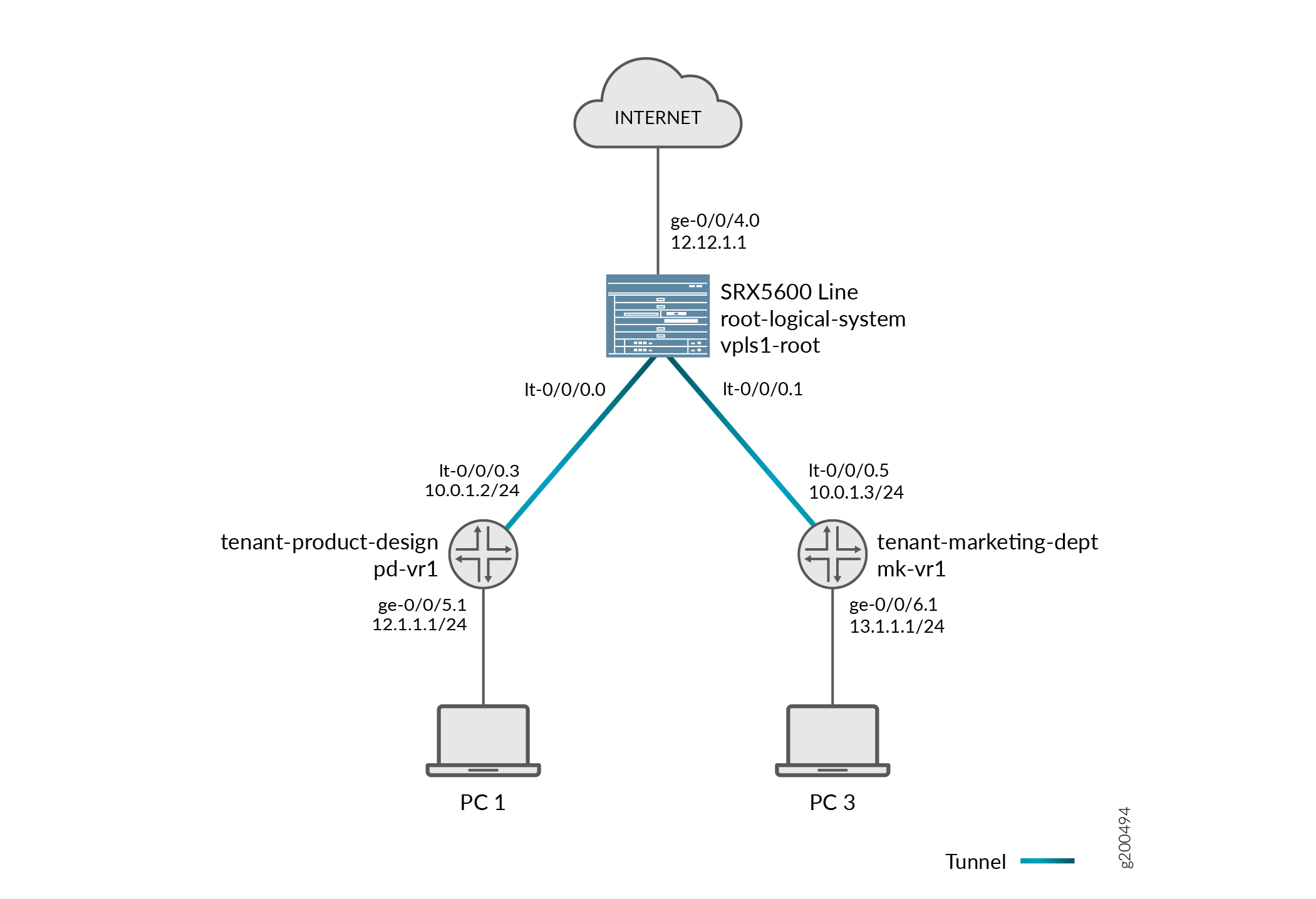
Pass-through traffic between tenant systems is complicated by fact that each tenant system has an ingress and an egress interface that the traffic must transit. It is as if traffic were coming into and going out from two devices. Consider how pass-through traffic is handled between tenant systems given in the topology shown in Figure 1.
Two sessions must be established for pass-through traffic between tenant systems. (Note that policy lookup is performed in both tenant systems).
-
On the incoming tenant system, one session is set up between the ingress interface (a physical interface) and its egress interface (an lt-0/0/0 interface).
-
On the egress tenant system, another session is set up between the ingress interface (the lt-0/0/0 interface of the second tenant system) and its egress interface (a physical interface).
Consider how pass-through traffic is handled across tenant systems in the topology shown in Figure 1.
-
A session is established in the incoming tenant system.
-
When a packet arrives on interface ge-0/0/5, it is identified as belonging to the tenant-product-design tenant system.
-
Because ge-0/0/5 belongs to the pd-vr1 routing instance, route lookup is performed in pd-vr1.
-
As a result of the lookup, the egress interface for the packet is identified as lt-0/0/0.3 with the next hop identified as lt-0/0/0.5, which is the ingress interface in the tenant-marketing-dept.
-
A session is established between ge-0/0/5 and lt-0/0/0.3.
-
-
A session is established in the outgoing tenant system.
-
The packet is injected into the flow again from lt-0/0/0.5, and the tenant system context identified as tenant-marketing-dept is derived from the interface.
-
Packet processing continues in the tenant-marketing-dept tenant system.
-
To identify the egress interface, route lookup for the packet is performed in the mk-vr1 routing instances.
-
The outgoing interface is identified as ge-0/0/6, and the packet is transmitted from the interface to the network.
-
Handling Self-Traffic
Self-traffic is traffic that originates in a tenant system on a device and is either sent out to the network from that tenant system or is terminated on another tenant system on the device.
Self-Initiated Traffic
Self-initiated traffic is generated from a source tenant system context and forwarded directly to the network from the tenant system interface.
The following process occurs:
-
When a packet is generated in a tenant system, a process for handling the traffic is started in the tenant system.
-
Route lookup is performed to identify the egress interface, and a session is established.
-
The tenant system performs a policy lookup and processes the traffic accordingly.
Consider how self-initiated traffic is handled across tenant systems given the topology shown in Figure 1.
-
A packet is generated in the tenant-product-design tenant system, and a process for handling the traffic is started in the tenant system.
-
Route lookup is performed in pd-vr2, and the egress interface is identified as ge-0/0/8.
-
A session is established.
-
The packet is transmitted to the network from ge-0/0/8.
Traffic Terminated on a Tenant System
When a packet enters the device on an interface belonging to a tenant system and the packet is destined for another tenant system on the device, the packet is forwarded between the tenant systems in the same manner as is pass-through traffic. However, route lookup in the second tenant system identifies the local egress interface as the packet destination. Consequently the packet is terminated on the second tenant system as self-traffic.
-
For terminated self-traffic, two policy lookups are performed, and two sessions are established.
-
On the incoming tenant system, one session is set up between the ingress interface (a physical interface) and its egress interface (an lt-0/0/0 interface).
-
On the destination tenant system, another session is set up between the ingress interface (the lt-0/0/0 interface of the second tenant system) and the local interface.
-
Consider how terminated self-traffic is handled across tenant systems in the topology shown in Figure 1.
-
A session is established in the incoming tenant system.
-
When a packet arrives on interface ge-0/0/5, it is identified as belonging to the tenant-product-design tenant system.
-
Because ge-0/0/5 belongs to the pd-vr1 routing instance, route lookup is performed in pd-vr1.
-
As a result of the lookup, the egress interface for the packet is identified as lt-0/0/0.3 with the next hop identified as lt-0/0/0.5, the ingress interface in the ls-marketing-dept.
-
A session is established between ge-0/0/5 and lt-0/0/0.3.
-
-
A management session is established in the destination tenant system.
-
The packet is injected into the flow again from lt-0/0/0.5, and the tenant system context identified as tenant-marketing-dept is derived from the interface.
-
Packet processing continues in the tenant-marketing-dept tenant system.
-
Route lookup for the packet is performed in the mk-vr1 routing instance. The packet is terminated in the destination tenant system as self-traffic.
-
Understanding Session and Gate Limitation Control
Sessions are created based on routing and other classification information to store information and allocate resources for a flow. The tenant systems flow module provides session and gate limitation to ensure that these resources are shared among the tenant systems. Resources allocation and limitations for each tenant system are specified in the security profile bound to the tenant system.
-
For session limiting, the system checks the first packet of a session against the maximum number of sessions configured for the tenant system. When the maximum limit of session is reached, the device drops the packet and logs the event.
-
For gate limiting, the device checks the first packet of a session against the maximum number of gates configured for the tenant system. If the maximum number of gates for a tenant system is reached, the device rejects the gate open request and logs the event.
About Configuring Sessions
Depending on the protocol and service, a session is programmed with a timeout value. For example, the default timeout for TCP is 1800 seconds. The default timeout for UDP is 60 seconds. When a flow is terminated, it is marked as invalid, and its timeout is reduced to 10 seconds. If no traffic uses the If no traffic uses the session before the service timeout, the session is aged out and freed to a common resource pool for reuse.
You can affect the life of a session in the following ways:
-
Age out sessions, based on how full the session table is.
-
Set an explicit timeout for aging out TCP sessions.
-
Configure a TCP session to be invalidated when it receives a TCP RST (reset) message.
-
You can configure sessions to accommodate other systems as follows:
-
Disable TCP packet security checks.
-
Change the maximum segment size.
-
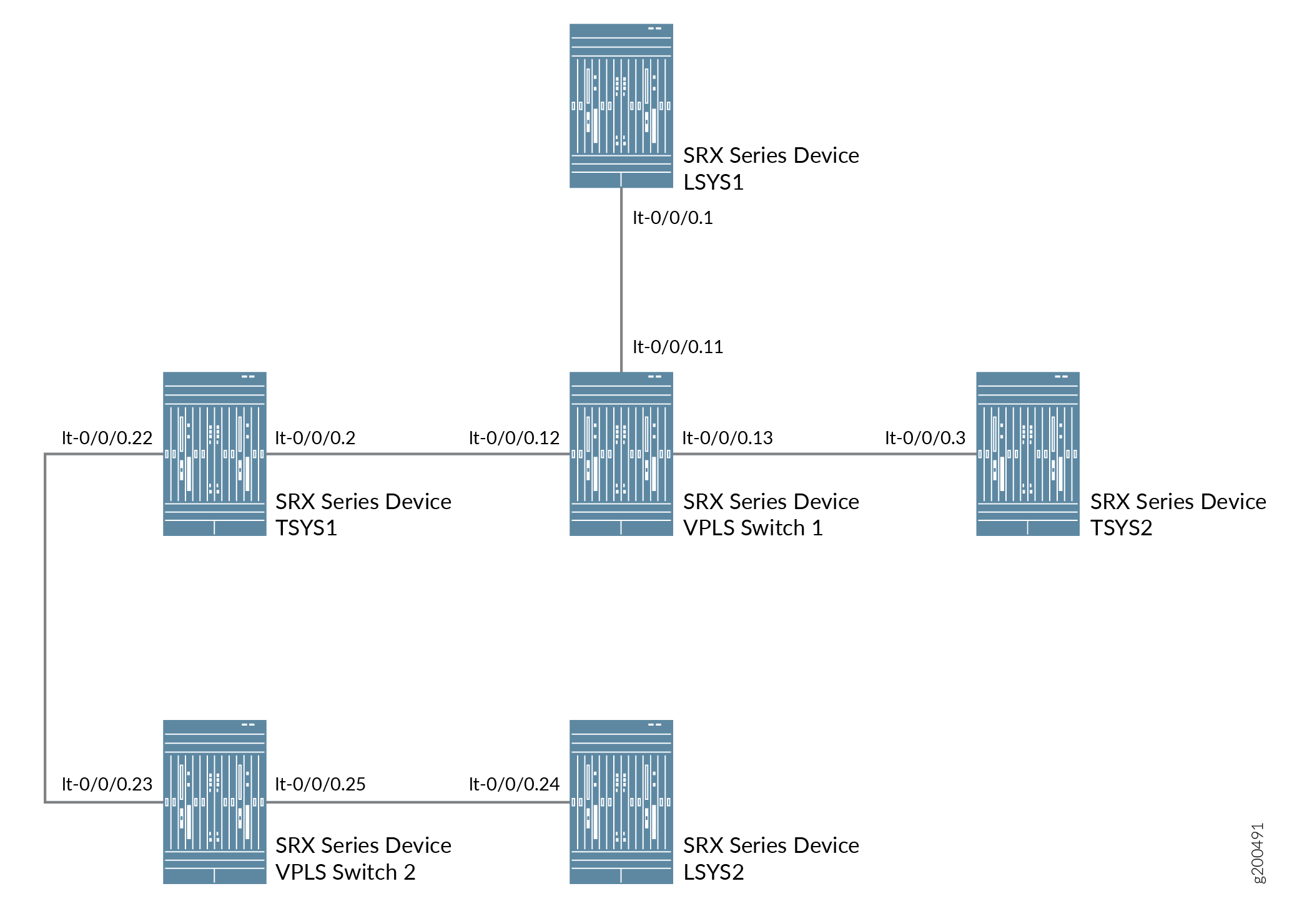
Configuring Logical Systems and Tenant Systems Interconnect with Multiple VPLS Switches
This example shows how to interconnect logical systems and tenant systems with multiple VPLS switches. This is achieved by configuring multiple logical systems and tenant systems with more than one logical tunnel (LT) interface under a tenant system and multiple VPLS switches that are configured to pass the traffic without leaving a security device.
Requirements
This example uses a security device running Junos OS with logical systems and tenant systems.
Overview
In this example, we configure multiple LT interfaces and multiple VPLS switches under one tenant system.
In this example, we also configure interconnection between multiple logical systems and tenant systems with LT interface point-to point connections (Encapsulation Ethernet and Encapsulation Frame-Relay).
For interconnected logical systems and tenant systems with multiple VPLS switches, this example configures logical tunnel interfaces lt-0/0/0 with ethernet-vpls as the encapsulation type. The corresponding peer lt-0/0/0 interfaces and security-profiles are assigned to the logical systems and tenant systems. The routing instance for the VPLS switch-1 and VPLS switch-2 are also assigned to the logical systems and tenant systems.
Figure 2 shows the topology for interconnected logical systems and tenant systems with multiple VPLS switches.
Configuration
To configure interfaces for the logical system and tenant system, perform these tasks:
CLI Quick Configuration
To quickly configure this example, copy the
following commands, paste them into a text file, remove any line breaks,
change any details necessary to match your network configuration,
copy and paste the commands into the CLI at the [edit] hierarchy
level, and then enter commit from configuration mode.
set interfaces lt-0/0/0 unit 11 encapsulation ethernet-vpls
set interfaces lt-0/0/0 unit 11 peer-unit 1
set interfaces lt-0/0/0 unit 12 encapsulation ethernet-vpls
set interfaces lt-0/0/0 unit 12 peer-unit 2
set interfaces lt-0/0/0 unit 13 encapsulation ethernet-vpls
set interfaces lt-0/0/0 unit 13 peer-unit 3
set interfaces lt-0/0/0 unit 23 encapsulation ethernet-vpls
set interfaces lt-0/0/0 unit 23 peer-unit 22
set interfaces lt-0/0/0 unit 25 encapsulation ethernet-vpls
set interfaces lt-0/0/0 unit 25 peer-unit 24
set routing-instances vpls-switch-1 instance-type vpls
set routing-instances vpls-switch-1 interface lt-0/0/0.11
set routing-instances vpls-switch-1 interface lt-0/0/0.12
set routing-instances vpls-switch-1 interface lt-0/0/0.13
set routing-instances vpls-switch-2 instance-type vpls
set routing-instances vpls-switch-2 interface lt-0/0/0.23
set routing-instances vpls-switch-2 interface lt-0/0/0.25
set logical-systems LSYS1 interfaces lt-0/0/0 unit 1 encapsulation ethernet
set logical-systems LSYS1 interfaces lt-0/0/0 unit 1 peer-unit 11
set logical-systems LSYS1 interfaces lt-0/0/0 unit 1 family inet address 192.168.0.1/24
set interfaces lt-0/0/0 unit 2 encapsulation ethernet
set interfaces lt-0/0/0 unit 2 peer-unit 12
set interfaces lt-0/0/0 unit 2 family inet address 192.168.0.2/24
set interfaces lt-0/0/0 unit 22 encapsulation ethernet
set interfaces lt-0/0/0 unit 22 peer-unit 23
set interfaces lt-0/0/0 unit 22 family inet address 192.168.4.1/30
set tenants TSYS1 routing-instances vr11 instance-type virtual-router
set tenants TSYS1 routing-instances vr11 interface lt-0/0/0.2
set tenants TSYS1 routing-instances vr11 interface lt-0/0/0.22
set interfaces lt-0/0/0 unit 3 encapsulation ethernet
set interfaces lt-0/0/0 unit 3 peer-unit 13
set interfaces lt-0/0/0 unit 3 family inet address 192.168.0.3/24
set tenants TSYS2 routing-instances vr12 instance-type virtual-router
set tenants TSYS2 routing-instances vr12 interface lt-0/0/0.3
set logical-systems LSYS2 interfaces lt-0/0/0 unit 24 encapsulation ethernet
set logical-systems LSYS2 interfaces lt-0/0/0 unit 24 peer-unit 25
set logical-systems LSYS2 interfaces lt-0/0/0 unit 24 family inet address 192.168.4.2/30
set system security-profile SP-user policy maximum 100
set system security-profile SP-user policy reserved 50
set system security-profile SP-user zone maximum 60
set system security-profile SP-user zone reserved 10
set system security-profile SP-user flow-session maximum 100
set system security-profile SP-user flow-session reserved 50
set system security-profile SP-user logical-system LSYS1
set system security-profile SP-user tenant TSYS1
set system security-profile SP-user tenant TSYS2
set system security-profile SP-user logical-system LSYS2
Procedure
Step-by-Step Procedure
The following example requires you to navigate various levels in the configuration hierarchy. For instructions on how to do that, see Using the CLI Editor in Configuration Mode.
-
Configure the lt-0/0/0 interfaces.
[edit]
user@host# set interfaces lt-0/0/0 unit 11 encapsulation ethernet-vpls
user@host# set interfaces lt-0/0/0 unit 11 peer-unit 1
user@host# set interfaces lt-0/0/0 unit 12 encapsulation ethernet-vpls
user@host# set interfaces lt-0/0/0 unit 12 peer-unit 2
user@host# set interfaces lt-0/0/0 unit 13 encapsulation ethernet-vpls
user@host# set interfaces lt-0/0/0 unit 13 peer-unit 3
user@host# set interfaces lt-0/0/0 unit 23 encapsulation ethernet-vpls
user@host# set interfaces lt-0/0/0 unit 23 peer-unit 22
user@host# set interfaces lt-0/0/0 unit 25 encapsulation ethernet-vpls
user@host# set interfaces lt-0/0/0 unit 25 peer-unit 24
-
Configure the routing instance for the VPLS switches and add interfaces to it.
[edit]
user@host# set routing-instances vpls-switch-1 instance-type vpls
user@host# set routing-instances vpls-switch-1 interface lt-0/0/0.11
user@host# set routing-instances vpls-switch-1 interface lt-0/0/0.12
user@host# set routing-instances vpls-switch-1 interface lt-0/0/0.13
user@host# set routing-instances vpls-switch-2 instance-type vpls
user@host# set routing-instances vpls-switch-2 interface lt-0/0/0.23
user@host# set routing-instances vpls-switch-2 interface lt-0/0/0.25
-
Configure LSYS1 with lt-0/0/0.1 interface and peer lt-0/0/0.11.
[edit]
user@host# set logical-systems LSYS1 interfaces lt-0/0/0 unit 1 encapsulation ethernet
user@host# set logical-systems LSYS1 interfaces lt-0/0/0 unit 1 peer-unit 11
user@host# set logical-systems LSYS1 interfaces lt-0/0/0 unit 1 family inet address 192.168.0.1/24
-
Configure TSYS1 with lt-0/0/0.2 interface and peer lt-0/0/0.12.
[edit]
user@host# set interfaces lt-0/0/0 unit 2 encapsulation ethernet
user@host# set interfaces lt-0/0/0 unit 2 peer-unit 12
user@host# set interfaces lt-0/0/0 unit 2 family inet address 192.168.0.2/24
user@host# set interfaces lt-0/0/0 unit 22 encapsulation ethernet
user@host# set interfaces lt-0/0/0 unit 22 peer-unit 23
user@host# set interfaces lt-0/0/0 unit 22 family inet address 192.168.4.1/30
user@host# set tenants TSYS1 routing-instances vr11 instance-type virtual-router
user@host# set tenants TSYS1 routing-instances vr11 interface lt-0/0/0.2
user@host# set tenants TSYS1 routing-instances vr11 interface lt-0/0/0.22
-
Configure TSYS2 with lt-0/0/0.3 interface and peer lt-0/0/0.13
[edit]
user@host# set interfaces lt-0/0/0 unit 3 encapsulation ethernet
user@host# set interfaces lt-0/0/0 unit 3 peer-unit 13
user@host# set interfaces lt-0/0/0 unit 3 family inet address 192.168.0.3/24
user@host# set tenants TSYS2 routing-instances vr12 instance-type virtual-router
user@host# set tenants TSYS2 routing-instances vr12 interface lt-0/0/0.3
-
Configure LSYS2 with lt-0/0/0 interface and peer-unit 24.
[edit]
user@host# set logical-systems LSYS2 interfaces lt-0/0/0 unit 24 encapsulation ethernet
user@host# set logical-systems LSYS2 interfaces lt-0/0/0 unit 24 peer-unit 25
user@host# set logical-systems LSYS2 interfaces lt-0/0/0 unit 24 family inet address 192.168.4.2/30
-
Assign security-profile for logical-systems.
[edit]
user@host# set system security-profile SP-user policy maximum 100
user@host# set system security-profile SP-user policy reserved 50
user@host# set system security-profile SP-user zone maximum 60
user@host# set system security-profile SP-user zone reserved 10
user@host# set system security-profile SP-user flow-session maximum 100
user@host#set system security-profile SP-user flow-session reserved 50
user@host# set system security-profile SP-user logical-system LSYS1
user@host# set system security-profile SP-user tenant TSYS1
user@host# set system security-profile SP-user tenant TSYS2
user@host# set system security-profile SP-user logical-system LSYS2
Results
-
From configuration mode, confirm your configuration by entering the
show interfaces lt-0/0/0, command. If the output does not display the intended configuration, repeat the configuration instructions in this example to correct itunit 2 { encapsulation ethernet; peer-unit 12; family inet { address 192.168.0.2/24; } } unit 3 { encapsulation ethernet; peer-unit 13; family inet { address 192.168.0.3/24; } } unit 11 { encapsulation ethernet-vpls; peer-unit 1; } unit 12 { encapsulation ethernet-vpls; peer-unit 2; } unit 13 { encapsulation ethernet-vpls; peer-unit 3; } unit 22 { encapsulation ethernet; peer-unit 23; family inet { address 192.168.4.1/30; } } unit 23 { encapsulation ethernet-vpls; peer-unit 22; } unit 25 { encapsulation ethernet-vpls; peer-unit 24; } -
From configuration mode, confirm your configuration by entering the
show routing-instances, command. If the output does not display the intended configuration, repeat the configuration instructions in this example to correct it.[edit] user@host# show routing-instances vpls-switch-1 { instance-type vpls; interface lt-0/0/0.11; interface lt-0/0/0.12; interface lt-0/0/0.13; } vpls-switch-2 { instance-type vpls; interface lt-0/0/0.23; interface lt-0/0/0.25; } -
From configuration mode, confirm your configuration by entering the
show logical-systems LSYS1, command. If the output does not display the intended configuration, repeat the configuration instructions in this example to correct it.[edit] user@host# show logical-systems LSYS1 interfaces { lt-0/0/0 { unit 1 { encapsulation ethernet; peer-unit 11; family inet { address 192.168.0.1/24; } } } } -
From configuration mode, confirm your configuration by entering the
show logical-systems LSYS2, command. If the output does not display the intended configuration, repeat the configuration instructions in this example to correct it.[edit] user@host# show tenants TSYS1 routing-instances { vr11 { instance-type virtual-router; interface lt-0/0/0.2; interface lt-0/0/0.22; } } -
From configuration mode, confirm your configuration by entering the
show logical-systems LSYS3, command. If the output does not display the intended configuration, repeat the configuration instructions in this example to correct it.[edit] user@host# show tenants TSYS2 routing-instances { vr12 { instance-type virtual-router; interface lt-0/0/0.3; } } -
From configuration mode, confirm your configuration by entering the
show logical-systems LSYS2, command. If the output does not display the intended configuration, repeat the configuration instructions in this example to correct it.[edit] user@host# show logical-systems LSYS2 interfaces { lt-0/0/0 { unit 24 { encapsulation ethernet; peer-unit 25; family inet { address 192.168.4.2/30; } } } } -
From configuration mode, confirm your configuration by entering the
show system security-profile, command. If the output does not display the intended configuration, repeat the configuration instructions in this example to correct it.[edit] user@host# show system security-profile SP-user { policy { maximum 100; reserved 50; } zone { maximum 60; reserved 10; } flow-session { maximum 100; reserved 50; } logical-system [ LSYS1 LSYS2 ]; tenant [ TSYS1 TSYS2 ]; }
If you are done configuring the device, enter commit from configuration mode.
Verification
To confirm that the configuration is working properly, perform these tasks:
Verifying the Security-Profile for Logical-systems
Purpose
Verify security profile for each logical systems.
Action
From operational mode, enter the show system security-profile
security-log-stream-number logical-system all command.
user@host> show system security-profile assignment summary
                                    Total     Maximum
security-profiles                       1          65
logical-systems                         1          32
tenants                                 0          32
logical-systems and tenants             1          64
Meaning
The output provides the usage and reserved values for the logical systems when security-log-stream is configured.
Verifying the LT Interfaces for Logical systems
Purpose
Verify interfaces for logical systems.
Action
From operational mode, enter the show interfaces
lt-0/0/0 terse command.
user@host> show interfaces lt-0/0/0 terse
Interface               Admin Link Proto    Local                 Remote
lt-0/0/0                up    up
lt-0/0/0.1              up    up   inet     192.168.0.1/24
lt-0/0/0.2              up    up   inet     192.168.0.2/24
lt-0/0/0.3              up    up   inet     192.168.0.3/24
lt-0/0/0.11             up    up   vpls
lt-0/0/0.12             up    up   vpls
lt-0/0/0.13             up    up   vpls
lt-0/0/0.22             up    up   inet     192.168.4.1/30
lt-0/0/0.23             up    up   vpls
lt-0/0/0.24             up    up   inet     192.168.4.2/30
lt-0/0/0.25             up    up   vpls
lt-0/0/0.32767          up    up
Meaning
The output provides the status of LT interfaces. All the LT interfaces are up.
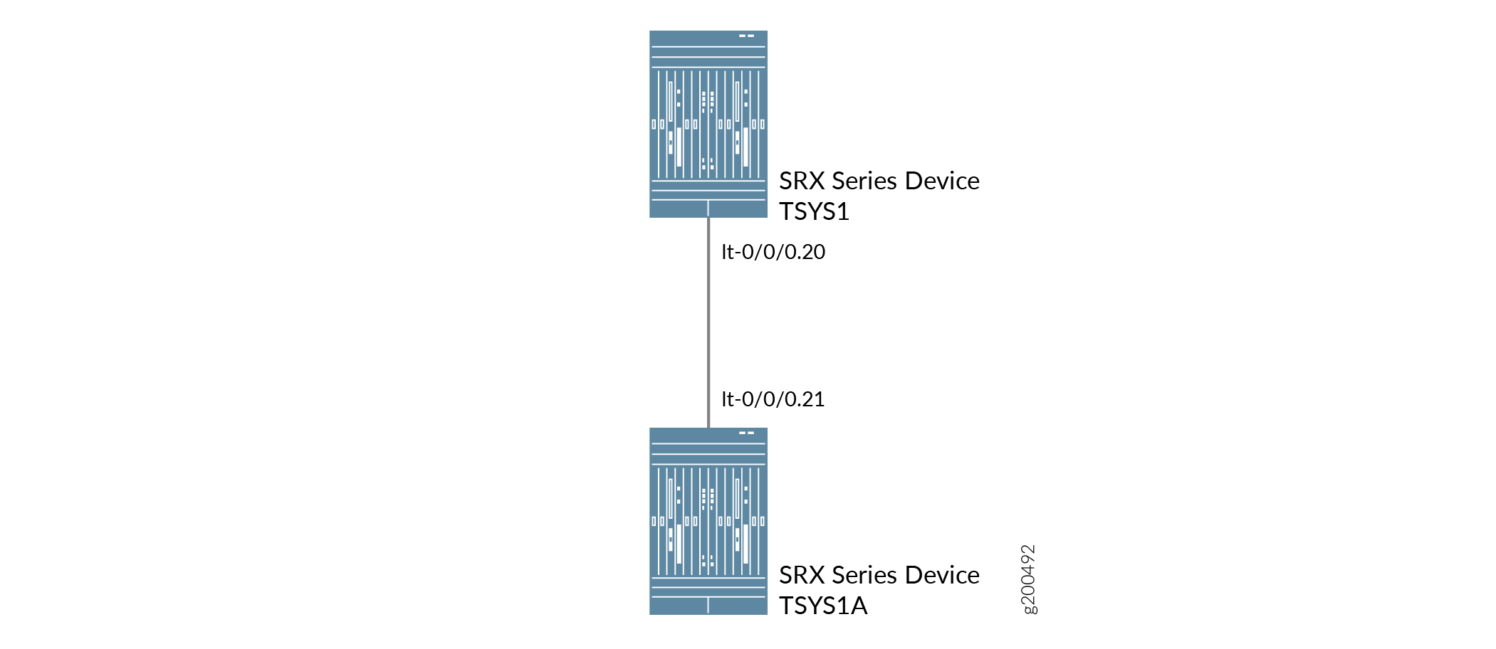
Configuring tenant systems Interconnect with Logical Tunnel Interface point-to-point connection
This example shows how to interconnect tenant systems with logical tunnel (LT) interfaces in a point-to-point connection.
Requirements
This example uses a security device running Junos OS with logical systems and tenant systems.
Overview
In this example we show how to interconnect tenant systems with logical tunnel (LT) interface in a point-to-point connection.
For the interconnected tenant systems with a point-to-point connection (encapsulation frame-relay) LT interface, this example configures the logical tunnel interface lt-0/0/0. This example configures security-zone and assigns interfaces to the logical systems.
The interconnected logical system lt-0/0/0 interface is configured with frame-relay as the encapsulation type. The corresponding peer lt-0/0/0 interfaces in the tenant systems are configured with frame-relay as the encapsulation type. A security profile is assigned to the tenant systems.
Figure 3 shows the topology for interconnected tenant systems with a point-to-point connection LT interface.
Configuration
To configure security-zone and assigns interfaces to tenant systems, perform these tasks:
CLI Quick Configuration
To quickly configure this example, copy the
following commands, paste them into a text file, remove any line breaks,
change any details necessary to match your network configuration,
copy and paste the commands into the CLI at the [edit] hierarchy
level, and then enter commit from configuration mode.
set system security-profile sp1 tenant TSYS1
set system security-profile sp2 tenant TSYS1A
set interfaces xe-0/0/5 gigether-options redundant-parent reth0
set interfaces xe-0/0/6 gigether-options redundant-parent reth1
set interfaces xe-1/0/5 gigether-options redundant-parent reth0
set interfaces xe-1/0/6 gigether-options redundant-parent reth1
set interfaces reth0 redundant-ether-options redundancy-group 2
set interfaces reth1 redundant-ether-options redundancy-group 1
set interfaces lt-0/0/0 unit 20 encapsulation ethernet
set interfaces lt-0/0/0 unit 20 peer-unit 21
set interfaces lt-0/0/0 unit 20 family inet address 198.51.1.20/24
set interfaces reth0 unit 0 family inet address 198.51.100.1/24
set interfaces lt-0/0/0 unit 21 encapsulation ethernet
set interfaces lt-0/0/0 unit 21 peer-unit 20
set interfaces lt-0/0/0 unit 21 family inet address 198.51.1.21/24
set interfaces reth1 unit 0 family inet address 192.0.2.1/24
set tenants TSYS1 routing-instances vr11 instance-type virtual-router
set tenants TSYS1 routing-instances vr11 interface lt-0/0/0.20
set tenants TSYS1 routing-instances vr11 interface reth0.0
set tenants TSYS1 routing-instances vr11 routing-options static route 192.0.2.0/24 next-hop 198.51.1.21
set tenants TSYS1 security policies default-policy permit-all
set tenants TSYS1 security zones security-zone trust host-inbound-traffic system-services all
set tenants TSYS1 security zones security-zone trust host-inbound-traffic protocols all
set tenants TSYS1 security zones security-zone trust interfaces reth0.0
set tenants TSYS1 security zones security-zone untrust host-inbound-traffic system-services all
set tenants TSYS1 security zones security-zone untrust host-inbound-traffic protocols all
set tenants TSYS1 security zones security-zone untrust interfaces lt-0/0/0.20
set tenants TSYS1A routing-instances vr12 instance-type virtual-router
set tenants TSYS1A routing-instances vr12 interface lt-0/0/0.21
set tenants TSYS1A routing-instances vr12 interface reth1.0
set tenants TSYS1A routing-instances vr12 routing-options static route 198.51.100.0/24 next-hop 198.51.1.20
set tenants TSYS1A security policies default-policy permit-all
set tenants TSYS1A security zones security-zone trust host-inbound-traffic system-services all
set tenants TSYS1A security zones security-zone trust host-inbound-traffic protocols all
set tenants TSYS1A security zones security-zone trust interfaces reth1.0
set tenants TSYS1A security zones security-zone untrust host-inbound-traffic system-services all
set tenants TSYS1A security zones security-zone untrust host-inbound-traffic protocols all
set tenants TSYS1A security zones security-zone untrust interfaces lt-0/0/0.21
Configuring [item]
Step-by-Step Procedure
The following example requires you to navigate various levels in the configuration hierarchy. For instructions on how to do that, see Using the CLI Editor in Configuration Mode.
-
Define a security profile sp1 and assign to a tenant system TNI. Define another security profile sp1 and assign to a tenant system TSYS1A
[edit]
user@host# set system security-profile sp1 tenant TSYS1
user@host# set system security-profile sp2 tenant TSYS1A
-
Set the interface for reth0 and reth1 and assign it to the redundancy group 1 and redundancy group 2.
[edit]
set interfaces xe-0/0/5 gigether-options redundant-parent reth0
set interfaces xe-0/0/6 gigether-options redundant-parent reth1
set interfaces xe-1/0/5 gigether-options redundant-parent reth0
set interfaces xe-1/0/6 gigether-options redundant-parent reth1
set interfaces reth0 redundant-ether-options redundancy-group 2
set interfaces reth1 redundant-ether-options redundancy-group 1
-
Set the LT interface as encapsulation ethernet in the tenant system TSYS1.
[edit]
user@host# set interfaces lt-0/0/0 unit 20 encapsulation ethernet
-
Configure a peer unit relationship between LT interfaces, thus creating a point-to-point connection.
[edit]
user@host# set interfaces lt-0/0/0 unit 20 peer-unit 21
-
Specify the IP address for the LT interface.
[edit]
user@host# set interfaces lt-0/0/0 unit 20 family inet address 198.51.1.20/24
-
Specify the IP address for the reth0.
[edit]
user@host# set interfaces reth0 unit 0 family inet address 198.51.100.1/24
-
Set the LT interface as encapsulation ethernet in the tenant system TSYS1A.
[edit]
user@host# set interfaces lt-0/0/0 unit 21 encapsulation ethernet
-
Configure a peer unit relationship between LT interfaces, thus creating a point-to-point connection.
[edit]
user@host# set interfaces lt-0/0/0 unit 21 peer-unit 20
-
Specify the IP address for the LT interface.
[edit]
user@host# set interfaces lt-0/0/0 unit 21 family inet address 198.51.1.21/24
-
Specify the IP address for the reth1.
[edit]
user@host# set interfaces reth1 unit 0 family inet address 192.0.2.1/24
-
Define the routing-instances for TSYS1.
[edit]
set tenants TSYS1 routing-instances vr11 instance-type virtual-router
set tenants TSYS1 routing-instances vr11 interface lt-0/0/0.20
set tenants TSYS1 routing-instances vr11 interface reth0.0
set tenants TSYS1 routing-instances vr11 routing-options static route 192.0.2.0/24 next-hop 198.51.1.21
-
Configure a security policy that permits all traffics.
[edit]
user@host# set tenants TSYS1 security policies default-policy permit-all
-
Configure security zones.
[edit]
set tenants TSYS1 security zones security-zone trust host-inbound-traffic system-services all
set tenants TSYS1 security zones security-zone trust host-inbound-traffic protocols all
set tenants TSYS1 security zones security-zone trust interfaces reth0.0
set tenants TSYS1 security zones security-zone untrust host-inbound-traffic system-services all
set tenants TSYS1 security zones security-zone untrust host-inbound-traffic protocols all
set tenants TSYS1 security zones security-zone untrust interfaces lt-0/0/0.20
-
Define the routing-instances for TSYS1A.
[edit]
set tenants TSYS1A routing-instances vr12 instance-type virtual-router
set tenants TSYS1A routing-instances vr12 interface lt-0/0/0.21
set tenants TSYS1A routing-instances vr12 interface reth1.0
set tenants TSYS1A routing-instances vr12 routing-options static route 198.51.100.0/24 next-hop 198.51.1.20
-
Configure a security policy that permits all traffics.
[edit]
set tenants TSYS1A security policies default-policy permit-all
-
Configure security zones.
[edit]
set tenants TSYS1A security zones security-zone trust host-inbound-traffic system-services all
set tenants TSYS1A security zones security-zone trust host-inbound-traffic protocols all
set tenants TSYS1A security zones security-zone trust interfaces reth1.0
set tenants TSYS1A security zones security-zone untrust host-inbound-traffic system-services all
set tenants TSYS1A security zones security-zone untrust host-inbound-traffic protocols all
set tenants TSYS1A security zones security-zone untrust interfaces lt-0/0/0.21
Results
-
From configuration mode, confirm your configuration by entering the
show tenants TSYS1commands. If the output does not display the intended configuration, repeat the configuration instructions in this example to correct it.[edit] user@host# show tenants TSYS1 routing-instances { vr11 { instance-type virtual-router; interface lt-0/0/0.20; interface reth0.0; routing-options { static { route 192.0.2.0/24 next-hop 198.51.1.21; } } } } security { policies { default-policy { permit-all; } } zones { security-zone trust { host-inbound-traffic { system-services { all; } protocols { all; } } interfaces { reth0.0; } } security-zone untrust { host-inbound-traffic { system-services { all; } protocols { all; } } interfaces { lt-0/0/0.20; } } } }
-
From configuration mode, confirm your configuration by entering the
show tenants TSYS1Acommands. If the output does not display the intended configuration, repeat the configuration instructions in this example to correct it.[edit] user@host# show tenants TSYS1A routing-instances { vr12 { instance-type virtual-router; interface lt-0/0/0.21; interface reth1.0; routing-options { static { route 198.51.100.0/24 next-hop 198.51.1.20; } } } } security { policies { default-policy { permit-all; } } zones { security-zone trust { host-inbound-traffic { system-services { all; } protocols { all; } } interfaces { reth1.0; } } security-zone untrust { host-inbound-traffic { system-services { all; } protocols { all; } } interfaces { lt-0/0/0.21; } } } }
If you are done configuring the device, enter commit from configuration mode.
Verification
To confirm that the configuration is working properly, perform these tasks:
Verifying the Security-Profile for all tenant systems
Purpose
Verify security profile for each logical systems.
Action
From operational mode, enter the show system security-profile
zone tenant al command.
user@host> show system security-profile zone tenant al
logical-system tenant name   security profile name       usage    reserved     maximum

T1                          bronze                          1           0        2048
T1A                           pX                              0           0        2048
Meaning
The output provides the usage and reserved values for the logical systems when security-log-stream is configured.
Configuring Logical System and Tenant System Interconnect with a Logical Tunnel Interface point-to-point connection
This example shows how to interconnect logical systems and tenant systems with logical tunnel (LT) interface in a point-to-point connection.
Requirements
This example uses a security device running Junos OS with logical systems and tenant systems.
Overview
In this example we show how to interconnect logical systems and tenant systems with logical tunnel (LT) interface point-to-point connection.
For the interconnect logical system and tenant system with a point-to-point connection LT interface, the example configures logical tunnel interfaces lt-0/0/0. This example configures security-zone and assigns interfaces to the logical systems
To interconnect the logical system and tenant system, lt-0/0/0 interfaces are configured with Ethernet as the encapsulation type. The corresponding peer lt-0/0/0 interfaces are configured with Ethernet as the encapsulation type. A security profile is assigned to the logical system and tenant system
Figure 4 shows the topology for interconnected logical systems and tenant systems with LT interface point-to-point connection.

Configuration
To configure security-zone and assigns interfaces to logical systems, perform these tasks:
CLI Quick Configuration
To quickly configure this example, copy the
following commands, paste them into a text file, remove any line breaks,
change any details necessary to match your network configuration,
copy and paste the commands into the CLI at the [edit] hierarchy
level, and then enter commit from configuration mode.
set system security-profile SP-user tenant TSYS2
set interfaces lt-0/0/0 unit 30 encapsulation ethernet
set interfaces lt-0/0/0 unit 30 peer-unit 31
set interfaces lt-0/0/0 unit 30 family inet address 192.255.2.1/30
set tenants TSYS2 routing-instances vr11 instance-type virtual-router
set tenants TSYS2 routing-instances vr11 interface lt-0/0/0.30
set security zones security-zone LT interfaces lt-0/0/0.30
set system security-profile SP-user logical-system LSYS3A
set logical-systems LSYS3A interfaces lt-0/0/0 unit 21 encapsulation ethernet
set logical-systems LSYS3A interfaces lt-0/0/0 unit 21 peer-unit 20
set logical-systems LSYS3A interfaces lt-0/0/0 unit 21 family inet address 192.255.2.2/30
set logical-systems LSYS3A security policies from-zone LT to-zone LT policy LT match source-address any
set logical-systems LSYS3A security policies from-zone LT to-zone LT policy LT match destination-address any
set logical-systems LSYS3A security policies from-zone LT to-zone LT policy LT match application any
set logical-systems LSYS3A security policies from-zone LT to-zone LT policy LT then permit
set logical-systems LSYS3A security policies default-policy permit-all
set logical-systems LSYS3A security zones security-zone LT host-inbound-traffic system-services all
set logical-systems LSYS3A security zones security-zone LT host-inbound-traffic protocols all
set logical-systems LSYS3A security zones security-zone LT interfaces lt-0/0/0.31
Procedure
Step-by-Step Procedure
The following example requires you to navigate various levels in the configuration hierarchy. For instructions on how to do that, see Using the CLI Editor in Configuration Mode in the Junos OS CLI User Guide.
-
Define a security profile and assign to a tenant system.
[edit]
user@host# set system security-profile SP-user tenant TSYS2
-
Set the LT interface as encapsulation ethernet in the tenant system.
[edit]
user@host# set interfaces lt-0/0/0 unit 20 encapsulation ethernet
-
Configure a peer relationship for tenant systems TSYS2.
[edit]
user@host# set interfaces lt-0/0/0 unit 20 peer-unit 21
-
Specify the IP address for the LT interface.
[edit]
user@host# set interfaces lt-0/0/0 unit 20 family inet address 192.255.2.1/30
-
Set the security zone for the LT interface.
[edit]
user@host# set logical-systems LSYS2 security zones security-zone LT interfaces lt-0/0/0.30
-
Define a security profile and assign to a logical system.
[edit]
user@host# set system security-profile SP-user logical-system LSYS3A
-
Define the routing-instances for TSYS2.
[edit]
set tenants TSYS2 routing-instances vr11 instance-type virtual-router
set tenants TSYS2 routing-instances vr11 interface lt-0/0/0.30
-
Set the LT interface as encapsulation ethernet in the logical system 3A.
[edit]
user@host# set logical-systems LSYS3A interfaces lt-0/0/0 unit 21 encapsulation ethernet
-
Configure a peer relationship for logical systems LSYS3A.
[edit]
user@host# set logical-systems LSYS3A interfaces lt-0/0/0 unit 21 peer-unit 20
-
Specify the IP address for the LT interface.
[edit]
user@host# set logical-systems LSYS3A interfaces lt-0/0/0 unit 21 family inet address 192.255.2.2/30
-
Configure a security policy that permits traffic from the LT zone to the LT policy LT zone.
[edit]
user@host# set logical-systems LSYS3A security policies from-zone LT to-zone LT policy LT match source-address any
user@host# set logical-systems LSYS3A security policies from-zone LT to-zone LT policy LT match destination-address any
user@host# set logical-systems LSYS3A security policies from-zone LT to-zone LT policy LT match application any
user@host# set logical-systems LSYS3A security policies from-zone LT to-zone LT policy LT then permit
-
Configure a security policy that permits traffic from default-policy.
[edit]
user@host# set logical-systems LSYS3A security policies default-policy permit-all
-
Configure security zones.
[edit]
user@host# set logical-systems LSYS3A security zones security-zone LT host-inbound-traffic system-services all
user@host# set logical-systems LSYS3A security zones security-zone LT host-inbound-traffic protocols all
user@host# set logical-systems LSYS3A security zones security-zone LT interfaces lt-0/0/0.31
Results
-
From configuration mode, confirm your configuration by entering the
show tenants TSYS2command. If the output does not display the intended configuration, repeat the configuration instructions in this example to correct it.[edit] user@host# show tenants TSYS2 routing-instances { vr11 { instance-type virtual-router; interface lt-0/0/0.30; } } -
From configuration mode, confirm your configuration by entering the
show logical-systems LSYS3Acommand. If the output does not display the intended configuration, repeat the configuration instructions in this example to correct it.[edit] user@host# show logical-systems LSYS3A interfaces { lt-0/0/0 { unit 21 { encapsulation ethernet; peer-unit 20; family inet { address 192.255.2.2/30; } } } } security { policies { from-zone LT to-zone LT { policy LT { match { source-address any; destination-address any; application any; } then { permit; } } } default-policy { permit-all; } } zones { security-zone LT { host-inbound-traffic { system-services { all; } protocols { all; } } interfaces { lt-0/0/0.31; } } } }
If you are done configuring the device, enter commit from configuration mode.
Verification
To confirm that the configuration is working properly, perform these tasks:
- Verifying the LT Interfaces for all Logical and tenant systems
- Verifying the Security-Profile for all Logical-systems
Verifying the LT Interfaces for all Logical and tenant systems
Purpose
Verify interfaces for logical systems.
Action
From operational mode, enter the show system security-profile
zone all-logical-systems-tenants command.
user@host> show system security-profile zone all-logical-systems-tenants
logical-system tenant name   security profile name       usage    reserved     maximum

root-logical-system          Default-Profile                 1           0        2048
LSYS3A1                        gold                            1           0        2048
TSYS23                          bronze                          1           0        2048
Meaning
The output provides the status of LT interfaces. All the LT interfaces are up.
Verifying the Security-Profile for all Logical-systems
Purpose
Verify security profile for each logical systems.
Action
From operational mode, enter the show system security-profile
security-log-stream-number logical-system all command.
user@host> show system security-profile security-log-stream-number logical-system all
logical system name   security profile name       usage    reserved   maximum
root-logical-system   Default-Profile                 2           0          2000
LSYS3A                 SP-user                         1          10          60
Meaning
The output provides the usage and reserved values for the logical systems when security-log-stream is configured.