ADSL Interfaces
Learn about ADSL interfaces and how to configure the ADSL interfaces on security devices.
ADSL Overview
Asymmetric digital subscriber line (ADSL) technology is part of the xDSL family of modem technologies that uses existing twisted-pair telephone lines to transport high-bandwidth data.
Interface Details |
Description |
|---|---|
Interface name |
ADSL |
Supported on |
For information about platforms support, see hardware compatibility tool (HCT). |
Interface type |
|
ADSL/ADSL2/ADSL2+ use cases |
|
For information about ADSL2 hardware specifications, see 1-Port ADSL2+ Mini-Physical Interface Module Network Interface Specifications.
Features Supported on the ADSL and ADSL2 Interfaces
Use Feature Explorer to confirm platform and release support for specific features.
Feature |
Description |
|---|---|
ADSL Features |
|
DSL |
|
ATM CoS Support |
Ability of a network to guarantee CoS depends on the way in which the source generates cells and on the availability of network resources. Based on the way in which the source generates cells and the availability of network resources, the set of traffic descriptors specified are:
|
Encapsulation |
Enable an existing Junos OS CLI to support MLPPP encapsulation and the family mlppp. To establish an ADSL link:
|
For more information about supported features and profiles on ADSL2 interfaces, see 1-Port ADSL2+ Mini-Physical Interface Module Key Features.
ADSL transmission is asymmetric because the downstream bandwidth is typically greater than the upstream bandwidth.
Operating Modes |
Upstream |
Downstream |
|---|---|---|
ADSL |
800 Kbps—1 Mbps |
8 Mbps |
ADSL2 |
1—1.5 Mbps |
12—14 Mbps |
ADSL2+ |
1—1.5 Mbps |
24—25 Mbps |
ADSL2+ Annex M |
2.5—3 Mbps |
25 Mbps |
Example: Configure ADSL Network Interfaces
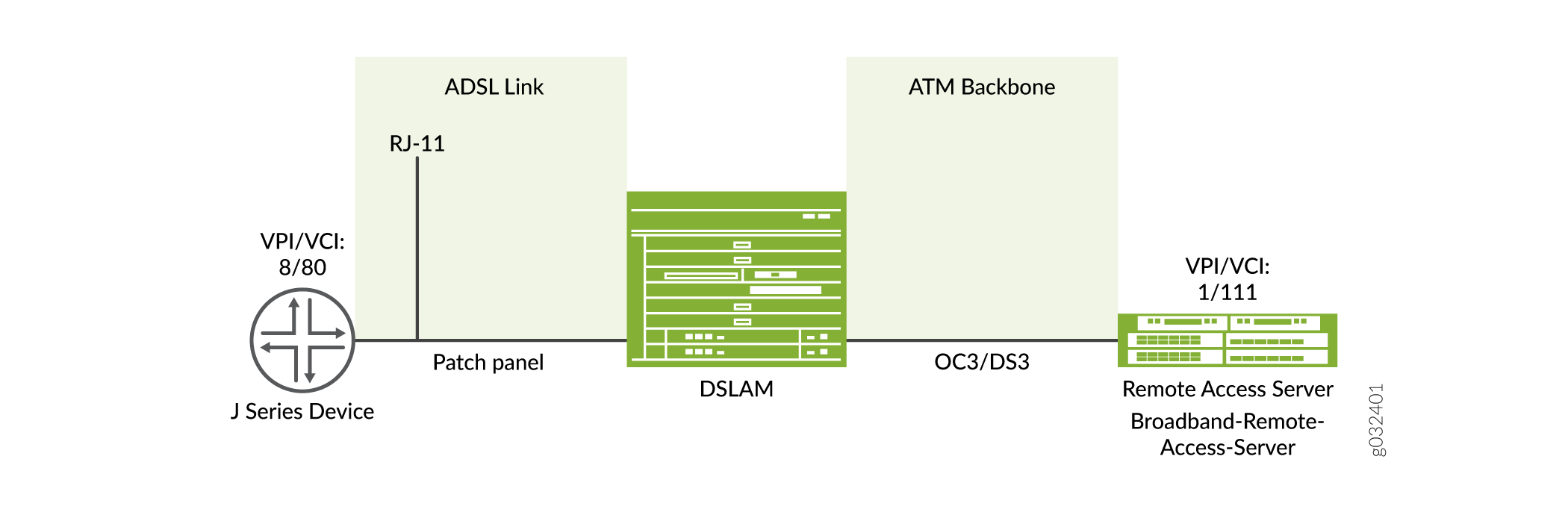
In this example, configure the ADSL interface on an SRX firewall which supports LFI through an MLPPP. To support MLPPP encapsulation and the family mlppp on the ADSL interface on an SRX Series Firewall, you enable an existing Junos OS CLI. To establish an ADSL link between network devices, you must use some intermediate connections. First, use an RJ-11 cable to connect the CPE (for example, an SRX Series Firewall) to a DSLAM patch panel to form an ADSL link. Then use OC3 or DS3 to connect the DSLAM to M Series or E Series devices to form an ATM backbone.
Configuration Step |
CLI Quick Configuration Commands |
|---|---|
Configure the DHCP client on ADSL interface |
set interfaces at-1/0/0 encapsulation ethernet-over-atm set interfaces at-1/0/0 atm-options vpi 2 set interfaces at-1/0/0 dsl-options operating-mode auto set interfaces at-1/0/0 unit 0 set interfaces at-1/0/0 unit 0 encapsulation ether-over-atm-llc set interfaces at-1/0/0 unit 0 vci 2.122 set interfaces at-1/0/0 unit 0 family inet set interfaces at-1/0/0 unit 0 family inet dhcp |
Configure the IPv6 address on an ADSL interface |
set interfaces at-1/0/0 encapsulation ethernet-over-atm set interfaces at-1/0/0 atm-options vpi 2 set interfaces at-1/0/0 unit 0 encapsulation ether-over-atm-llc set interfaces at-1/0/0 unit 0 vci 2.118 set interfaces at-1/0/0 unit 0 family inet6 address 13:13::1/64 |
Configure ATM-over-ADSL network interfaces |
set interfaces at-2/0/0 atm-options vpi 25 oam-liveness up-count 200 down-count 200 set interfaces at-2/0/0 atm-options vpi 25 oam-period 100 set interfaces at-1/0/0 unit 0 shaping cbr set interfaces at-1/0/0 unit 0 shaping vbr peak 33000 set interfaces at-1/0/0 dsl-options operating-mode auto set interfaces at-1/0/0 encapsulation ethernet-over-atm set interfaces at-1/0/0 unit 3 encapsulation atm-nlpid oam-liveness up-count 200 down-count 200 set interfaces at-1/0/0 unit 3 oam-period 100 set interfaces at-1/0/0 unit 3 family inet set interfaces at-1/0/0 unit 3 vci 35 |
Configure CHAP on DSL interfaces |
set access profile A-ppp-client client client1 chap-secret my-secret set interfaces at-3/0/0 unit 0 ppp-options chap access-profile A-ppp-client local-name A-at-3/0/0.0 passive |
Configure the DHCP client on ADSL interface
In this example, you configure the ATM interface as at-1/0/0. Then set the
logical interface to unit 0 and specify the family protocol type as
inet. Finally, configure the DHCP client. To configure DHCP client on
ADSL interfaces:
Use the show interfaces at-1/0/0 command to see the
output of the configuration.
Configure the IPv6 Address on an ADSL Interface
To configure the IPv6 address on an ADSL interface:
Configure the encapsulation type.
[edit]
user@host# set interfaces at-1/0/0 encapsulation ethernet-over-atm
Specify the annex type.
[edit]
user@host# set interfaces at-1/0/0 atm-options vpi 2
Configure the encapsulation for the logical unit.
[edit] user@host# set interfaces at-1/0/0 unit 0 encapsulation ether-over-atm-llc
Configure the VCI value.
[edit] user@host# set interfaces at-1/0/0 unit 0 vci 2.118
Configure family protocol type and assign an IPv6 address.
[edit] user@host# set interfaces at-1/0/0 unit 0 family inet6 address 13:13::1/64
Use the show interfaces at-1/0/0 command to see the
output of the configuration.
Configure ATM-over-ADSL Network Interfaces
This example shows how to use devices with ADSL Annex A or Annex B PIMs to send network traffic through a point-to-point connection to a DSLAM. Within the example, you set the DSL operating mode type to auto so that the ADSL interface will autonegotiate settings with the DSLAM.
The example shows how to create an ATM interface called at-2/0/0. The values for the interface’s physical properties are kept relatively low—
-
The ATM VPI is set to 25
-
Both the OAM down and up counts are 200 cells
-
The OAM period is set to 100 seconds
The example also shows how to set traffic shaping values on the ATM interface to support CoS. CBR is enabled in order to stabilize the cell transmission rate throughout the duration of the connection. Additionally, the VBR peak is set to 33,000 for data packet transfers.
Within the example, set the encapsulation mode to ethernet-over-atm to support PPP over Ethernet IPv4 traffic. Also configure a logical interface (unit 3). The logical interface uses ATM NLPID encapsulation. As with the physical interface, the OAM down count and up count are set to 200 cells on the logical interface. The OAM period is set to 100 seconds. The family protocol is set to inet, and the VCI is set to 35.
On SRX Series Firewalls, the ATM interface takes more than 5 minutes to boot when CPE is configured in ANSI-DMT mode and CO is configured in automode. This occurs only with ALU 7300 DSLAM, due to limitation in current firmware version running on the ADSL Mini-PIM.
To configure ATM-over-ADSL network interfaces for the devices:
Create an ATM interface.
[edit]
user@host# edit interfaces at-2/0/0
Configure the physical properties for the ATM interface.
[edit interfaces at-2/0/0]
user@host# set atm-options vpi 25
user@host# set atm-options vpi 25 oam-liveness up-count 200 down-count 200
user@host# set atm-options vpi 25 oam-period 100
Specify the CBR value and VBR value for the Ethernet interface.
[edit]
user@host# edit interfaces at-1/0/0 unit 0
user@host# set shaping cbr
user@host# set shaping vbr peak 33000
Set the DSL operating mode type.
[edit interfaces at-1/0/0.0]
user@host# set dsl-options operating-mode auto
Configure the encapsulation type.
[edit interfaces at-1/0/0]
user@host# set encapsulation ethernet-over-atm
Configure the encapsulation for the logical unit.
[edit interfaces at-1/0/0 unit 3]
user@host# set encapsulation atm-nlpid
Configure the OAM liveness values for an ATM virtual circuit.
[edit interfaces at-1/0/0 unit 3]
user@host# set oam-liveness up-count 200 down-count 200
Specify the OAM period.
[edit interfaces at-1/0/0 unit 3]
user@host# set oam-period 100
Set the family protocol type.
[edit interfaces at-1/0/0 unit 3]
user@host# set family inet
Configure the VCI value.
[edit interfaces at-1/0/0 unit 3]
user@host# set vci 35
Use the show command to see the output of the configuration.
Configure MLPPP-over-ADSL Interfaces
In this example, you set the encapsulation as atm-mlppp-llc
for the interface at-5/0/0. You then configure the family
MLPPP bundle as lsq-0/0/0.1.
Figure 1 shows a typical example of MLPPP-over-ADSL end-to-end connectivity.
To configure MLPPP on an ADSL interface:
Configure an interface.
[edit]
user@host# edit interfaces at-5/0/0 unit 0
Set the MLPPP encapsulation.
[edit interfaces at-5/0/0 unit 0]
user@host# set encapsulation atm-mlppp-llc
Specify the family MLPPP.
[edit interfaces at-5/0/0 unit 0]
user@host# set family mlppp bundle lsq-0/0/0.1
If you are done configuring the device, commit the configuration.
[edit]
user@host# commit
Use the show command to see the output of the configuration.
Configure CHAP on DSL Interfaces
In this example, specify the CHAP access profile and create an interface called
at-3/0/0. Configure CHAP on the ATM-over-ADSL interface. Specify a unique
profile name called A-ppp-client containing a client list and access parameters. Then
specify a unique hostname called A-at-3/0/0.0 to be used in CHAP. Finally,
set the passive option to handle incoming CHAP packets. To configure CHAP on the
ATM-over-ADSL interface:
Define a CHAP access profile.
[edit]
user@host# set access profile A-ppp-client client client1 chap-secret my-secret
Create an interface.
[edit]
user@host# edit interfaces at-3/0/0 unit 0
Configure CHAP and specify a unique profile name.
[edit interfaces at-3/0/0 unit 0]
user@host# set ppp-options chap access-profile A-ppp-client
Specify a unique hostname.
[edit interfaces at-3/0/0 unit 0]
user@host# set ppp-options chap local-name A-at-3/0/0.0
Set the option to handle incoming CHAP packets only.
[edit interfaces at-3/0/0 unit 0]
user@host# set ppp-options chap passive
Use the show command to see the output of the configuration.
Verification
Display information about the parameters configured on the ADSL interfaces.
To verify that the DHCP options are configured use the
run show system services dhcp clientcommand:user@host#run show system services dhcp client Logical Interface name at-1/0/0.0 Hardware address 00:1f:12:e4:71:38 Client status bound Address obtained 10.40.1.2 Update server disabled Lease obtained at 2011-05-03 04:58:10 PDT Lease expires at 2011-05-04 04:58:10 PDT DHCP options: Name: server-identifier, Value: 10.40.1.1 Code: 1, Type: ip-address, Value: 255.255.255.0 Name: name-server, Value: [ 192.168.5.68, 192.168.60.131, 172.17.28.100, 172.17.28.101 ] Name: domain-name, Value: englab.juniper.netTo verify the interface status and check traffic statistics use the
show interface
              terse
command and test end-to-end datapath connectivity by sending the ping packets to the remote end IP address:user@host#run show interfaces at-1/0/0 terse Interface Admin Link Proto Local Remote at-1/0/0 up up at-1/0/0.0 up up inet 10.40.1.2/24 at-1/0/0.32767 up upuser@host#run ping 10.40.1.1 count 100 rapid PING 10.40.1.1 (10.40.1.1): 56 data bytes !!!!!!!!!!!!!!!!!!!!!!!!!!!!!!!!!!!!!!!!!!!!!!!!!!!!!!!!!!!!!!!!!!!!!!!!!!!!!!!!!!!!!!!!!!!!!!!!!!!! --- 10.40.1.1 ping statistics --- 100 packets transmitted, 100 packets received, 0% packet loss round-trip min/avg/max/stddev = 20.086/26.404/61.723/6.194 msTo verify that the ADSL interface properties are configured use the
show ipv6 neighborscommand. The output shows a summary of interface information.user@host> show ipv6 neighbors IPv6 Address Linklayer Address State Exp Rtr Secure Interface 10:1::2 00:00:0a:00:00:00 reachable 17 yes no reth0.0 13:13::1 00:19:e2:4b:61:83 stale 1197 yes no at-1/0/0.0 12:12::2 00:19:e2:4b:61:83 stale 1188 yes no at-3/0/0.0
The
IPv6 Addressfield displays the configured IPv6 address on the interface.To verify the ADSL interface properties, use the
show interfaces at-1/0/0 extensivecommand:user@host> show interfaces at-1/0/0 extensive Physical interface: at-1/0/0, Enabled, Physical link is Up Interface index: 141, SNMP ifIndex: 49, Generation: 142 Link-level type: ATM-PVC, MTU: 4482, Clocking: Internal, ADSL mode, Speed: ADSL, Loopback: None Device flags : Present Running Link flags : None CoS queues : 8 supported, 8 maximum usable queues Hold-times : Up 0 ms, Down 0 ms Current address: 00:05:85:c3:17:f4 Last flapped : 2008-06-26 23:11:09 PDT (01:41:30 ago) Statistics last cleared: Never Traffic statistics: Input bytes : 0 0 bps Output bytes : 0 0 bps Input packets: 0 0 pps Output packets: 0 0 pps Input errors: Errors: 0, Drops: 0, Invalid VCs: 0, Framing errors: 0,Policed discards: 0, L3 incompletes: 0, L2 channelerrors: 0, L2 mismatch timeouts: 0, Resource errors: 0 Output errors: Carrier transitions: 3, Errors: 0, Drops: 0, Aged packets: 0, MTU errors: 0, Resource errors: 0 ADSL alarms : None ADSL defects : None ADSL media: Seconds Count State LOF 1 1 OK LOS 1 1 OK LOM 0 0 OK LOP 0 0 OK LOCDI 0 0 OK LOCDNI 0 0 OK ADSL status: Modem status : Showtime (Adsl2plus) DSL mode : Auto Annex A Last fail code: None Subfunction : 0x00 Seconds in showtime : 6093 ADSL Chipset Information: ATU-R ATU-C Vendor Country : 0x0f 0xb5 Vendor ID : STMI IFTN Vendor Specific: 0x0000 0x70de ADSL Statistics: ATU-R ATU-C Attenuation (dB) : 0.0 0.0 Capacity used(%) : 100 92 Noise margin(dB) : 7.5 9.0 Output power (dBm) : 10.0 12.5 Interleave Fast Interleave Fast Bit rate (kbps) : 0 24465 0 1016 CRC : 0 0 0 0 FEC : 0 0 0 0 HEC : 0 0 0 0 Received cells : 0 49 Transmitted cells : 0 0 ATM status: HCS state: Hunt LOC : OK ATM Statistics: Uncorrectable HCS errors: 0, Correctable HCS errors: 0,Tx cell FIFO overruns: 0,Rx cell FIFO overruns: 0,Rx cell FIFO underruns: 0, Input cell count: 49, Output cell count: 0,Output idle cell count: 0,Output VC queue drops: 0Input no buffers: 0, Input length errors: 0, Input timeouts: 0, Input invalid VCs: 0, Input bad CRCs: 0, Input OAM cell no buffers: 0 Packet Forwarding Engine configuration: Destination slot: 1 Direction : Output CoS transmit queue Bandwidth Buffer Priority Limit % bps % usec 0 best-effort 95 7600000 95 0 low none 3 network-control 5 400000 5 0 low none But for ADSL MiniPim TI chipset does not send ADSL Chipset Information. Also Adsl minipim does not send any alarms. So we can't show alarm stats for minipim. So following information will not be displayed in Minipim case. ADSL alarms : None ADSL defects : None ADSL media: Seconds Count State LOF 1 1 OK LOS 1 1 OK LOM 0 0 OK LOP 0 0 OK LOCDI 0 0 OK LOCDNI 0 0 OK ADSL Chipset Information: ATU-R ATU-C Vendor Country : 0x0f 0xb5 Vendor ID : STMI IFTN Vendor Specific: 0x0000 0x70deThe output shows a summary of interface information.
To verify the PPPoA configuration for an ATM-over-ADSL interface is correct, use the
show interfaces at-1/0/0and theshow accesscommands.To verify the configuration for an MLPPP-over-ADSL Interface is correct, use the
show interfaces at-5/0/0command.To verify that the ADSL interface properties are enabled, use the
show interfaces at-3/0/0 extensivecommand.user@host> show interfaces at-3/0/0 extensive Physical interface: at-3/0/0, Enabled, Physical link is Up Interface index: 141, SNMP ifIndex: 49, Generation: 142 Link-level type: ATM-PVC, MTU: 4482, Clocking: Internal, ADSL mode, Speed: ADSL, Loopback: None Device flags : Present Running Link flags : None CoS queues : 8 supported, 8 maximum usable queues Hold-times : Up 0 ms, Down 0 ms Current address: 00:05:85:c3:17:f4 Last flapped : 2008-06-26 23:11:09 PDT (01:41:30 ago) Statistics last cleared: Never Traffic statistics: Input bytes : 0 0 bps Output bytes : 0 0 bps Input packets: 0 0 pps Output packets: 0 0 pps Input errors: Errors: 0, Drops: 0, Invalid VCs: 0, Framing errors: 0,Policed discards: 0, L3 incompletes: 0, L2 channelerrors: 0, L2 mismatch timeouts: 0, Resource errors: 0 Output errors: Carrier transitions: 3, Errors: 0, Drops: 0, Aged packets: 0, MTU errors: 0, Resource errors: 0 ADSL alarms : None ADSL defects : None ADSL media: Seconds Count State LOF 1 1 OK LOS 1 1 OK LOM 0 0 OK LOP 0 0 OK LOCDI 0 0 OK LOCDNI 0 0 OK ADSL status: Modem status : Showtime (Adsl2plus) DSL mode : Auto Annex A Last fail code: None Subfunction : 0x00 Seconds in showtime : 6093 ADSL Chipset Information: ATU-R ATU-C Vendor Country : 0x0f 0xb5 Vendor ID : STMI IFTN Vendor Specific: 0x0000 0x70de ADSL Statistics: ATU-R ATU-C Attenuation (dB) : 0.0 0.0 Capacity used(%) : 100 92 Noise margin(dB) : 7.5 9.0 Output power (dBm) : 10.0 12.5 Interleave Fast Interleave Fast Bit rate (kbps) : 0 24465 0 1016 CRC : 0 0 0 0 FEC : 0 0 0 0 HEC : 0 0 0 0 Received cells : 0 49 Transmitted cells : 0 0 ATM status: HCS state: Hunt LOC : OK ATM Statistics: Uncorrectable HCS errors: 0, Correctable HCS errors: 0,Tx cell FIFO overruns: 0,Rx cell FIFO overruns: 0,Rx cell FIFO underruns: 0, Input cell count: 49, Output cell count: 0,Output idle cell count: 0,Output VC queue drops: 0Input no buffers: 0, Input length errors: 0, Input timeouts: 0, Input invalid VCs: 0, Input bad CRCs: 0, Input OAM cell no buffers: 0 Packet Forwarding Engine configuration: Destination slot: 1 Direction : Output CoS transmit queue Bandwidth Buffer Priority Limit % bps % usec 0 best-effort 95 7600000 95 0 low none 3 network-control 5 400000 5 0 low none But for ADSL MiniPim TI chipset does not send ADSL Chipset Information. Also Adsl minipim does not send any alarms. So we can't show alarm stats for minipim. So following information will not be displayed in Minipim case. ADSL alarms : None ADSL defects : None ADSL media: Seconds Count State LOF 1 1 OK LOS 1 1 OK LOM 0 0 OK LOP 0 0 OK LOCDI 0 0 OK LOCDNI 0 0 OK ADSL Chipset Information: ATU-R ATU-C Vendor Country : 0x0f 0xb5 Vendor ID : STMI IFTN Vendor Specific: 0x0000 0x70deTo verify the PPPoA configuration for an ATM-over-ADSL interface is correct, use the
show interfaces at-3/0/0and theshow accesscommands.