Configure Point-to-Point Protocol over Ethernet (PPPoE)
Learn about PPPoE Ethernet interfaces and CHAP authentication. Also, learn how to display statistics, set tracing options for PPPoE, and verify the interfaces on security devices.
PPPoE Overview
PPPoE combines PPP, which typically runs over broadband connections, with the Ethernet link-layer protocol that allows users to connect to a network of hosts over a bridge or access concentrator. PPPoE enables service providers to maintain access control through PPP connections and also manage multiple hosts at a remote site.
PPPoE connects multiple hosts on an Ethernet LAN to a remote site through a single customer premises equipment (CPE) device—a Juniper Networks device. Hosts share a common digital subscriber line (DSL), a cable modem, or a wireless connection to the Internet.
To use PPPoE, you must initiate a PPPoE session, encapsulate Point-to-Point Protocol (PPP) packets over Ethernet, and configure the device as a PPPoE client. To provide a PPPoE connection, each PPP session must learn the Ethernet address of the remote peer and establish a unique session identifier during the PPPoE discovery and session stages.
PPPoE has two stages, the discovery stage and the PPPoE session stage. In the discovery stage, the client discovers the access concentrator by identifying the Ethernet media access control (MAC) address of the access concentrator and establishing a PPPoE session ID. In the session stage, the client and the access concentrator build a point-to-point connection over Ethernet, based on the information collected in the discovery stage.
This topic contains the following sections:
PPPoE Discovery Stage
To initiate a PPPoE session, a host must first identify the Ethernet MAC address of the remote peer and establish a unique PPPoE session ID for the session. Learning the remote Ethernet MAC address is called PPPoE discovery.
During the PPPoE discovery process, the host does not discover a remote endpoint on the Ethernet network. Instead, the host discovers the access concentrator through which all PPPoE sessions are established. Discovery is a client/server relationship, with the host (a device running Junos OS) acting as the client and the access concentrator acting as the server. Because the network might have more than one access concentrator, the discovery stage allows the client to communicate with all of them and select one. A device cannot receive PPPoE packets from two different access concentrators on the same physical interface.
The PPPoE discovery stage consists of the following steps:
PPPoE Active Discovery Initiation (PADI)—The client initiates a session by broadcasting a PADI packet to the LAN to request a service.
PPPoE Active Discovery Offer (PADO)—Any access concentrator that can provide the service requested by the client in the PADI packet replies with a PADO packet that contains its own name, the unicast address of the client, and the service requested. An access concentrator can also use the PADO packet to offer other services to the client.
PPPoE Active Discovery Request (PADR)—From the PADOs it receives, the client selects one access concentrator based on its name or the services offered and sends it a PADR packet to indicate the service or services needed.
PPPoE Active Discovery Session-Confirmation (PADS)—When the selected access concentrator receives the PADR packet, it accepts or rejects the PPPoE session:
To accept the session, the access concentrator sends the client a PADS packet with a unique session ID for a PPPoE session and a service name that identifies the service under which it accepts the session.
To reject the session, the access concentrator sends the client a PADS packet with a service name error and resets the session ID to zero.
PPPoE Session Stage
The PPPoE session stage starts after the PPPoE discovery stage is over. The access concentrator can start the PPPoE session after it sends a PADS packet to the client, or the client can start the PPPoE session after it receives a PADS packet from the access concentrator. A device supports multiple PPPoE sessions on each interface, but no more than 256 PPPoE sessions per device.
Each PPPoE session is uniquely identified by the Ethernet address of the peer and the session ID. After the PPPoE session is established, data is sent as in any other PPP encapsulation. The PPPoE information is encapsulated within an Ethernet frame and is sent to a unicast address. Magic numbers, echo requests, and all other PPP traffic behave exactly as in normal PPP sessions. In this stage, both the client and the server must allocate resources for the PPPoE logical interface.
After a session is established, the client or the access concentrator can send a PPPoE Active Discovery Termination (PADT) packet anytime to terminate the session. The PADT packet contains the destination address of the peer and the session ID of the session to be terminated. After this packet is sent, the session is closed to PPPoE traffic.
If PPPoE session is already up and the user restarts the PPPoE daemon, a new PPPoE daemon with a new PID starts while the existing session is not terminated.
If PPPoE session is already down and user restarts the PPPoE daemon, the PPPoE discovery establishes a new session.
The PPPoE session is not terminated for the following configuration changes:
Changing idle time out value
Changing auto rec timer value
Deleting idle time out
Deleting auto rec timer
Add new auto rec time
Add new idle time out
Change negotiate address to static address
Change static ip address to a new static ip address
Changing default chap secrete
The PPPoE session is terminated for the following configuration changes:
Add ac name
Delete chap ppp options
Add new chap ppp options
Configure uifd mac
When the MTU for an underlying physical interface is changed, it brings down the PPPoE session. The PPPoE MTU can be greater than 1492 if the Ethernet or WAN connection supports RFC 4638 (Mini Jumbo Frames).
See Also
PPPoE Interfaces
The device’s Point-to-Point Protocol over Ethernet (PPPoE) interface to the access concentrator (AC) can be a Fast Ethernet interface, a GbE interface, or a redundant Ethernet interface. The PPPoE configuration is the same for all interfaces.
Use PPPoE over redundant Ethernet interface to confirm platform and release support.
The only difference is the encapsulation for the underlying interface to the AC:
If the interface is Ethernet, use a PPPoE encapsulation.
To configure a PPPoE interface, you create an interface with a logical interface unit 0, then specify a logical Ethernet interface as the underlying interface for the PPPoE session. Specify other PPPoE options, including the AC and PPPoE session parameters.
This feature allows an existing PPPoE session to continue without starting a new PPP0E session in the event of a failover.
Example: Configure PPPoE Interfaces
This example shows how to configure a PPPoE interface.
Requirements
Before you begin, configure an Ethernet interface. See Example: Configure Ethernet Interface.
Overview
In this example, you create the PPPoE interface pp0.0 and specify the logical Ethernet interface
ge-0/0/1.0 as the underlying interface. You also set the AC, set the PPPoE session
parameters, and set the MTU of the IPv4 family to 1492.
Configuration
Procedure
CLI Quick Configuration
To quickly configure the example, copy the following command, paste it into a text
file, and remove any line breaks. Then change any details necessary to match your
network configuration. Copy and paste the command into the CLI at the
[edit] hierarchy level, and enter commit from
configuration mode.
set interfaces pp0 unit 0 pppoe-options underlying-interface ge-0/0/1.0 access-concentrator ispl.com auto-reconnect 100 idle-timeout 100 client service-name video@ispl.com
set interfaces pp0 unit 0  family inet mtu 1492 negotiate-address
Step-by-Step Procedure
The following example requires you to navigate various levels in the configuration hierarchy. For instructions on how to do that, see Using the CLI Editor in Configuration Mode.
To configure a PPPoE interface:
Create a PPPoE interface.
[edit]
user@host# edit interfaces pp0 unit 0
Configure PPPoE options.
[edit interfaces pp0 unit 0]
user@host# set pppoe-options underlying-interface ge-0/0/1.0 access-concentrator ispl.com auto-reconnect 100 idle-timeout 100 client service-name video@ispl.com
Configure the MTU.
[edit interfaces pp0 unit 0]
user@host# set family inet mtu 1492
If you want to configure
mtuto a value above 1492 octets, then useppp-max-payloadoption. Refer ppoe-options for more details.Configure the PPPoE interface address.
[edit interfaces pp0 unit 0]
user@host# set family inet negotiate-address
Results
From configuration mode, confirm your configuration
by entering the show interfaces pp0 command. If the output
does not display the intended configuration, repeat the configuration
instructions in this example to correct it.
[edit]
    user@host# show interfaces pp0
unit 0 {
    pppoe-options {
        underlying-interface ge-0/0/1.0;
        idle-timeout 100;
        access-concentrator ispl.com;
        service-name "vide0@ispl.com";
        auto-reconnect 100;
        client;
     }
    family inet {
        mtu 1492;
        negotiate-address;
        }
    }
If you are done configuring the device, enter commit from configuration mode.
Verification
Confirm that the configuration is working properly.
Verify PPPoE Interfaces
Purpose
Verify that the PPPoE device interfaces are configured properly.
Action
From operational mode, enter the show interfaces
pp0 command.
user@host> show interfaces pp0
Physical interface: pp0, Enabled, Physical link is Up
  Interface index: 67, SNMP ifIndex: 317
  Type: PPPoE, Link-level type: PPPoE, MTU: 9192
  Device flags   : Present Running
  Interface flags: Point-To-Point SNMP-Traps
  Link type      : Full-Duplex
  Link flags     : None
  Last flapped   : Never
  Input rate     : 0 bps (0 pps)
  Output rate    : 0 bps (0 pps)

  Logical interface pp0.0 (Index 1) (SNMP ifIndex 330)
    Flags: Point-To-Point SNMP-Traps 16384 Encapsulation: PPPoE
    PPPoE:
      State: SessionUp, Session ID: 3304,
      Session AC name: isp1.com, AC MAC address: 00:90:1a:40:f6:4c,
      Service name: video@isp1.com, Configured AC name: isp1.com,
      Auto-reconnect timeout: 60 seconds
      Underlying interface: ge-5/0/0.0 (Index 71)
  Input packets : 23
  Output packets: 22
  Keepalive settings: Interval 10 seconds, Up-count 1, Down-count 3
  Keepalive: Input: 16 (00:00:26 ago), Output: 0 (never)
  LCP state: Opened
  NCP state: inet: Opened, inet6: Not-configured, iso: Not-configured, mpls:
  Not-configured
  CHAP state: Success
    Protocol inet, MTU: 1492
      Flags: Negotiate-Address
      Addresses, Flags: Kernel Is-Preferred Is-Primary
        Destination: 211.211.211.2, Local: 211.211.211.1
The output shows information about the physical and the logical interfaces. Verify the following information:
The physical interface is enabled and the link is up.
The PPPoE session is running on the correct logical interface.
For state, the state is active (up).
For underlying interface, the physical interface on which the PPPoE session is running is correct:
For an Ethernet connection, the underlying interface is Fast Ethernet or GbE—for example, ge-5/0/0.0.
Verify PPPoE Sessions
Purpose
Verify that a PPPoE session is running properly on the logical interface.
Action
From operational mode, enter the show pppoe interfaces command.
user@host> show pppoe interfaces
pp0.0 Index 67
  State: Session up, Session ID: 31,
  Service name: video@isp1.com, Configured AC name: isp1.com,
  Session AC name: belur, AC MAC address: 00:90:1a:40:f6:4e,
  Auto-reconnect timeout: 1 seconds,
  Underlying interface: ge-0/0/1.0 Index 69
The output shows information about the PPPoE sessions. Verify the following information:
The PPPoE session is running on the correct logical interface.
For state, the session is active (up).
For underlying interface, the physical interface on which the PPPoE session is running is correct:
For an Ethernet connection, the underlying interface is Fast Ethernet or GbE—for example, ge-0/0/1.0.
To clear a PPPoE session on the pp0.0 interface, use the clear pppoe sessions
pp0.0 command. To clear all sessions on the interface, use the
clear pppoe sessions command.
Verify the PPPoE Version
Purpose
Verify the version information of the PPPoE protocol configured on the device interfaces.
Action
From operational mode, enter the show pppoe version command.
user@host> show pppoe version
Point-to-Point Protocol Over Ethernet, version 1. rfc2516
   PPPoE protocol               = Enabled
   Maximum Sessions             = 256
   PADI resend timeout          = 2 seconds
   PADR resend timeout          = 16 seconds
   Max resend timeout           = 64 seconds
   Max Configured AC timeout    = 4 seconds
The output shows PPPoE protocol information. Verify the following information:
The correct version of the PPPoE protocol is configured on the interface.
For PPPoE protocol, the PPPoE protocol is enabled.
Verify PPPoE Statistics
Purpose
Verify the statistics information about PPPoE interfaces.
Action
From operational mode, enter the show pppoe statistics command.
user@host> show pppoe statistics
Active PPPoE sessions: 4
  PacketType                       Sent         Received
    PADI                            502                0
    PADO                              0              219
    PADR                            219                0
    PADS                              0              219
    PADT                              0              161
    Service name error                0                0
    AC system error                   0               13
    Generic error                     0                0
    Malformed packets                 0               41
    Unknown packets                   0                0
  Timeout
    PADI                             42
    PADO                              0
    PADR                              0
The output shows information about active sessions on PPPoE interfaces. Verify the following information:
Total number of active PPPoE sessions running on the interface
For packet type, the number of packets of each type sent and received during the PPPoE session
Disable the End-of-List Tag
During the PPPoE discovery stage, any AC that can provide the service requested by the client in
the PADI packet replies with a PADO packet. The PADO packet includes its own name, the
unicast address of the client, and the requested service text. An AC can also use the PADO
packet to offer other services to the client. When a client receives a PADO packet, and if
it encounters the End-of-List tag in the PADO packet, tags after the
End-of-List tag are ignored and the complete information is not processed
correctly. As a result, the PPPoE connection is not established correctly.
You can avoid some PPPoE connection errors by configuring the ignore-eol-tag
option to disable the End-of-List tag in the PADO packet.
Procedure
Step-by-Step Procedure
The following example requires you to navigate various levels in the configuration hierarchy. For instructions on how to do that, see Using the CLI Editor in Configuration Mode.
To disable the End-of-List tag:
Create a PPPoE interface.
[edit]user@host# set interfaces pp0 unit 0Configure PPPoE options.
[edit interfaces pp0 unit 0]user@host# set pppoe-options ignore-eol-tag
Results
From configuration mode, confirm your configuration
by entering the show interfaces pp0 command. If the output
does not display the intended configuration, repeat the configuration
instructions in this example to correct it.
[edit]
user@host# show interfaces pp0
unit 0 {
pppoe-options {
    ignore-eol-tag;
 }
If you are done configuring the device, enter commit from configuration mode.
Verify That the End-of-List Tag Is Disabled
Purpose
Verify the status of the End-of-List tag in the PPPoE configuration.
Action
From operational mode, enter the show interfaces
pp0.0 command.
user@host> show pppoe interfaces pp0.0
Logical interface pp0.0 (Index 78) (SNMP ifIndex 541)
    Flags: Point-To-Point SNMP-Traps 0x0 Encapsulation: PPPoE
    PPPoE:
      State: SessionUp, Session ID: 3,
      Session AC name: cell, Remote MAC address: 00:26:88:f7:77:83,
      Configured AC name: None, Service name: None,
      Auto-reconnect timeout: Never, Idle timeout: Never,
      Underlying interface: ge-0/0/3.0 (Index 77)
     Ignore End-Of-List tag: Enable
user@host> show pppoe interfaces pp0.0 extensive
pp0.0 Index 74
  State: Session up, Session ID: 1,
  Service name: None,
  Session AC name: cell, Configured AC name: None,
  Remote MAC address: 00:26:88:f7:77:83,
  Session uptime: 00:02:03 ago,
  Auto-reconnect timeout: 10 seconds, Idle timeout: Never,
  Underlying interface: ge-0/0/3.0 Index 73
  Ignore End-of-List tag: Enable
  PacketType                       Sent         Received
    PADI                             23                0
    PADO                              0                5
    PADR                             11                0
    PADS                              0                2
    PADT                              2                0
    Service name error                0                0
    AC system error                   0                0
    Generic error                     0                0
    Malformed packets                 0                0
    Unknown packets                   0                0
  Timeout
    PADI                              3
    PADO                              0
    PADR                              3
  Receive Error Counters
    PADI                              0
    PADO                              0
    PADR                              0
    PADS                              0
The output shows information about active sessions on PPPoE
interfaces. Verify that the Ignore End-of-List tag: Enable option is set.
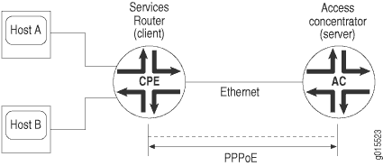
PPPoE Ethernet Interfaces
During a Point-to-Point Protocol over Ethernet (PPPoE) session, the device encapsulates each PPP frame in an Ethernet frame and transports the frames over an Ethernet loop. Figure 1 shows a typical PPPoE session between a device and an access concentrator on the Ethernet loop.
To configure PPPoE on an Ethernet interface, you configure encapsulation on the logical interface.
Example: Configure PPPoE Encapsulation on an Ethernet Interface
This example shows how to configure PPPoE encapsulation on an Ethernet interface.
Requirements
Before you begin:
Configure an Ethernet interface. See Example: Configure Ethernet Interface.
Configure a PPPoE encapsulation interface.
Overview
In this example, you configure PPPoE encapsulation on the ge-0/0/1 interface.
Configuration
Procedure
Step-by-Step Procedure
To configure PPPoE encapsulation:
Enable PPPoE encapsulation on the interface.
[edit]
user@host# set interfaces ge-0/0/1 unit 0 encapsulation ppp-over-ether
Commit the configuration if you are done configuring the device.
[edit]
user@host# commit
Verification
To verify the configuration is working properly,
enter the show interfaces ge-0/0/1 command.
Example: Configure PPPoE Encapsulation on an ATM-over-ADSL Interface
This example shows how to configure a physical interface for Ethernet over ATM encapsulation and how to create a logical interface for PPPoE over LLC encapsulation.
Requirements
Before you begin:
Configure network interfaces. See Example: Configure Ethernet Interface.
Configure PPPoE interfaces. See Example: Configuring PPPoE Interfaces.
Configure PPPoE encapsulation on an Ethernet interface. See Example: Configuring PPPoE Encapsulation on an Ethernet Interface.
Overview
In this example, you configure the physical interface at-2/0/0 for Ethernet over ATM encapsulation. As part of the configuration, you set the virtual path identifier (VPI) on an ATM-over-ADSL physical interface to 0, you set the ADSL operating mode to auto, and you set the encapsulation type to ATM-over-ADSL. Then you create a logical interface for PPPoE over LLC encapsulation.
Configuration
Procedure
CLI Quick Configuration
To quickly configure this example, copy the following command, paste it into a text file, remove any line breaks, change any details necessary to match your network configuration, copy and paste the command into the CLI at the [edit] hierarchy level, and then enter commit from configuration mode.
set interfaces at-2/0/0 atm-options vpi 0
set interfaces at-2/0/0 dsl-options operating-mode auto
set interfaces at-2/0/0 encapsulation ethernet-over-atm
set interfaces at-2/0/0 unit 0 encapsulation ppp-over-ether-over-atm-llc vci 0.120
Step-by-Step Procedure
The following example requires you to navigate various levels in the configuration hierarchy. For instructions on how to do that, see Using the CLI Editor in Configuration Mode.
To configure PPPoE encapsulation on an ATM-over-ADSL interface:
Configure the physical interface.
[edit]
user@host# edit interfaces at-2/0/0
Set the VPI on the interface.
[edit interfaces at-2/0/0]
user@host# set atm-options vpi 0
Configure the ADSL operating mode.
[edit interfaces at-2/0/0]
user@host# set dsl-options operating-mode auto
Configure PPPoE encapsulation.
[edit interfaces at-2/0/0]
user@host# set encapsulation ethernet-over-atm
Create a logical interface and configure LLC encapsulation.
[edit interfaces at-2/0/0]
user@host# set unit 0 encapsulation ppp-over-ether-over-atm-llc vci 0.120
Results
From configuration mode, confirm your configuration by entering the show interfaces at-2/0/0 command. If the output does not display the intended configuration, repeat the configuration instructions in this example to correct it.
[edit]
user@host# show interfaces at-2/0/0 {
    encapsulation ethernet-over-atm;
        atm-options {
        vpi 0;
    }
    dsl-options {
        operating-mode auto;
     }
    unit 0 {
        encapsulation ppp-over-ether-over-atm-llc;
        vci 0.120;
        }
    }
If you are done configuring the device, enter commit from configuration mode.
Verification
CHAP Authentication on a PPPoE Interface
For interfaces with PPPoE encapsulation, you can configure interfaces to support the PPP Challenge Handshake Authentication Protocol (CHAP). When you enable CHAP on an interface, the interface can authenticate its peer and be authenticated by its peer.
If you set the passive option to handle incoming
CHAP packets only, the interface does not challenge its peer. However,
if the interface is challenged, it responds to the challenge. If you
do not set the passive option, the interface always challenges
its peer.
You can configure RADIUS authentication of PPP sessions using CHAP. CHAP enables you to send RADIUS messages through a routing instance to customer RADIUS servers in a private network.
Example: Configure CHAP Authentication on a PPPoE Interface
This example shows how to configure CHAP authentication on a PPPoE interface.
Requirements
Before you begin:
Configure an Ethernet interface. See Example: Configure Ethernet Interface.
Configure a PPPoE interface. See Example: Configuring PPPoE Interfaces.
Overview
In this example, you configure a CHAP access profile, and then apply it to the PPPoE interface pp0. You also configure the hostname to be used in CHAP challenge and response packets, and set the passive option for handling incoming CHAP packets.
Configuration
Procedure
CLI Quick Configuration
To quickly configure this example, copy the following command, paste it into a text file, remove any line breaks, change any details necessary to match your network configuration, copy and paste the command into the CLI at the [edit] hierarchy level, and then enter commit from configuration mode.
set access profile A-ppp-client client client1 chap-secret my-secret
set interfaces pp0 unit 0 ppp-options chap access-profile A-ppp-client local-name A-ge-0/0/1.0 passive
Step-by-Step Procedure
The following example requires you to navigate various levels in the configuration hierarchy. For instructions on how to do that, see Using the CLI Editor in Configuration Mode.
To configure CHAP on a PPPoE interface:
Configure a CHAP access profile.
[edit]
user@host# set access profile A-ppp-client client client1 chap-secret my-secret
Enable CHAP options on the interface.
[edit]
user@host# edit interfaces pp0 unit 0 ppp-options chap
Configure the CHAP access profile on the interface.
[edit interfaces pp0 unit 0 ppp-options chap]
user@host# set access-profile A-ppp-client
Configure a hostname for the CHAP challenge and response packets.
[edit interfaces pp0 unit 0 ppp-options chap]
user@host# set local-name A-ge-0/0/1.0
Set the passive option to handle incoming CHAP packets only.
[edit interfaces pp0 unit 0 ppp-options chap]
user@host# set passive
Results
From configuration mode, confirm your configuration by entering the show interfaces command. If the output does not display the intended configuration, repeat the configuration instructions in this example to correct it.
[edit]
    user@host# show interfaces
    pp0 {
    unit 0 {
     ppp-options {
    chap {
    access-profile A-ppp-client;
    local-name A-ge-0/0/1.0;
    passive;
    }
    }
    }
}
If you are done configuring the device, enter commit from configuration mode.
Verify Credit-Flow Control
Purpose
Display PPPoE credit-flow control information about credits on each side of the PPPoE session when credit processing is enabled on the interface.
Action
user@host> show pppoe interface detail
pp0.51 Index 73
  State: Session up, Session ID: 3,
  Service name: None,
  Configured AC name: None, Session AC name: None,
  Remote MAC address: 00:22:83:84:2e:81,
  Session uptime: 00:05:48 ago,
  Auto-reconnect timeout: Never, Idle timeout: Never,
  Underlying interface: ge-0/0/4.1 Index 72
  PADG Credits: Local: 12345, Remote: 6789, Scale factor: 128 bytes
  PADQ Current bandwidth: 750 Kbps, Maximum 1000 Kbps
    Quality: 85, Resources 65, Latency 100 msec.
  Dynamic bandwidth: 3 Kbps
pp0.1000 Index 71
  State: Down, Session ID: 1,
  Service name: None,
  Configured AC name: None, Session AC name: None,
  Remote MAC address: 00:00:00:00:00:00,
  Auto-reconnect timeout: Never, Idle timeout: Never,
  Underlying interface: ge-0/0/1.0 Index 70
  PADG Credits: enabled
  Dynamic bandwidth: enabled
Verify PPPoE Interfaces
Purpose
Display PPPoE interfaces information.
Action
To display PPPoE interface information:
user@host> show pppoe interfaces pp0.51 detail
pp0.51 Index 75
  State: Session up, Session ID: 1,
  Service name: None,
  Configured AC name: None, Session AC name: None,
  Remote MAC address: 00:11:22:33:44:55,
  Session uptime: 00:04:18 ago,
  Auto-reconnect timeout: Never, Idle timeout: Never,
  Underlying interface: ge-0/0/1.0 Index 70
  PADQ Current bandwidth: 750 Kbps, Maximum 1000 Kbps
    Quality: 85, Resources 65, Latency 100 msec.
  Dynamic bandwidth: 3 Kbps
To display PPPoE terse interface information:
user@host> show pppoe interfaces terse pp0.51
Interface    Admin Link Proto    Local        Remote
		  pp0.51       up  up   inet   5.1.1.1     --> 5.1.1.2
								  inet6    fe80::21f:12ff:fed2:2918/64
                                feee::5:1:1:1/126
Display Statistics for PPPoE
Purpose
Display PPPoE statistics.
Action
user@host> show interfaces pp0.51 statistics
Logical interface pp0.51 (Index 75) (SNMP ifIndex 137)
    Flags: Point-To-Point SNMP-Traps 0x0 Encapsulation: PPPoE
    PPPoE:
      State: SessionUp, Session ID: 1,
      Session AC name: None, Remote MAC address: 00:22:83:84:2f:03,
      Underlying interface: ge-0/0/4.1 (Index 74)
    Input packets : 20865
    Output packets: 284636
  Keepalive settings: Interval 10 seconds, Up-count 1, Down-count 3
  Keepalive: Input: 0 (never), Output: 943 (00:00:06 ago)
  LCP state: Opened
  NCP state: inet: Opened, inet6: Opened, iso: Not-configured, mpls:
  Not-configured
  CHAP state: Closed
  PAP state: Closed
    Security: Zone: Null
    Protocol inet, MTU: 1492
      Flags: None
      Addresses, Flags: Is-Preferred Is-Primary
        Destination: 5.1.1.2, Local: 5.1.1.1
    Protocol inet6, MTU: 1492
      Flags: None
      Addresses, Flags: Is-Preferred
        Destination: fe80::/64, Local: fe80::21f:12ff:fed2:2918
      Addresses, Flags: Is-Preferred Is-Primary
        Destination: feee::5:1:1:0/126, Local: feee::5:1:1:1
Set Tracing Options for PPPoE
To trace the operations of the router’s PPPoE process, include the traceoptions statement at the [edit protocols pppoe] hierarchy level:
[edit protocols pppoe]
traceoptions {
    file filename <files number> <match regular-expression> <size size> <world-readable | no-world-readable>;
    flag flag;
    level severity-level;
    no-remote-trace;
}
To specify more than one tracing operation, include multiple flag statements.
You can specify the following flags in the traceoptions statement:
all—All areas of codeconfig—Configuration codeevents—Event codegres—Gres codeinit—Initialization codeinterface-db—Interface database codememory—Memory management codeprotocol—PPPoE protocol processing codertsock—Routing socket codesession-db—Session management codesignal—Signal handling codestate—State handling codetimer—Timer codeui—User interface code
Change History Table
Feature support is determined by the platform and release you are using. Use Feature Explorer to determine if a feature is supported on your platform.
ignore-eol-tag option to disable the End-of-List tag in the PADO packet.