Example: Configuring EVPN with IRB Solution
EVPN with IRB Solution Overview
A Data Center Service Provider (DCSP) hosts the data center for its multiple customers on a common physical network. To each customer (also called a tenant), the service looks like a full-fledged data center that can expand to 4094 VLANs and all private subnets. For disaster recovery, high availability, and optimization of resource utilization, it is common for the DCSP to span across the data center to more than one site. To deploy the data center services, a DCSP faces the following main challenges:
Extending Layer 2 domains across more than one data center site. This requires optimal intra-subnet traffic forwarding.
Supporting optimal inter-subnet traffic forwarding and optimal routing in the event of virtual machine (VM).
Supporting multiple tenants with independent VLAN and subnet space.
Ethernet VPN (EVPN) is targeted to handle all of the above mentioned challenges, wherein:
The basic EVPN functionality enables optimal intra-subnet traffic forwarding
Implementing the integrated routing and bridging (IRB) solution in an EVPN deployment enables optimal inter-subnet traffic forwarding
Configuring EVPN with virtual switch support enables multiple tenants with independent VLAN and subnet space
The following sections describe the IRB solution for EVPNs:
- Need for an EVPN IRB Solution
- Implementing the EVPN IRB Solution
- Benefits of Implementing the EVPN IRB Solution
Need for an EVPN IRB Solution
EVPN is a technology used to provide Layer 2 extension and interconnection across an IP/MPLS core network to different physical sites belonging to a single Layer 2 domain. In a data center environment with EVPN, there is a need for both Layer 2 (intra-subnet traffic) and Layer 3 (inter-subnet traffic) forwarding and potentially interoperation with tenant Layer 3 VPNs.
With only a Layer 2 solution, there is no optimum forwarding of inter-subnet traffic, even when the traffic is local, for instance, when both the subnets are on the same server.
With only a Layer 3 solution, the following issues for intra-subnet traffic can arise:
MAC address aliasing issue where duplicate MAC addresses are not detected.
TTL issue for applications that use TTL 1 to confine traffic within a subnet.
IPv6 link-local addressing and duplicate address detection that relies on Layer 2 connectivity.
Layer 3 forwarding does not support the forwarding semantics of a subnet broadcast.
Support of non-IP applications that require Layer 2 forwarding.
Because of the above mentioned shortcomings of a pure Layer 2 and Layer 3 solution, there is a need for a solution incorporating optimal forwarding of both Layer 2 and Layer 3 traffic in the data center environment when faced with operational considerations such as Layer 3 VPN interoperability and virtual machine (VM) mobility.
An EVPN-based integrated routing and bridging (IRB) solution provides optimum unicast and multicast forwarding for both intra-subnets and inter-subnets within and across data centers.
The EVPN IRB feature is useful for service providers operating in an IP/MPLS network that provides both Layer 2 VPN or VPLS services and Layer 3 VPN services who want to extend their service to provide cloud computation and storage services to their existing customers.
Implementing the EVPN IRB Solution
An EVPN IRB solution provides the following:
Optimal forwarding for intra-subnet (Layer 2) traffic.
Optimal forwarding for inter-subnet (Layer 3) traffic.
Support for ingress replication for multicast traffic.
Support for network-based as well as host-based overlay models.
Support for consistent policy-based forwarding for both Layer 2 and Layer 3 traffic.
Support for the following routing protocols on the IRB interface:
BFD
BGP
IS-IS
OSPF and OSPF version 3
Support for single-active and all-active multihoming
Junos OS supports several models of EVPN configuration to satisfy the individual needs of EVPN and data center cloud services customers. To provide flexibility and scalability, multiple bridge domains can be defined within a particular EVPN instance. Likewise, one or more EVPN instances can be associated with a single Layer 3 VPN virtual routing and forwarding (VRF). In general, each data center tenant is assigned a unique Layer 3 VPN VRF, while a tenant could comprise one or more EVPN instances and one or more bridge domains per EVPN instance. To support this model, each configured bridge domain (including the default bridge domain for an EVPN instance) requires an IRB interface to perform the Layer 2 and Layer 3 functions. Each bridge domain or IRB interface maps to a unique IP subnet in the VRF.
You can associate an IRB interface with the primary instance inet.0 table instead of a VRF in an EVPN IRB solution.
There are two major functions that are supported for IRB in EVPN.
Host MAC-IP synchronization
This includes:
Advertising the IP address along with the MAC advertisement route in EVPN. This is done by using the IP field in the EVPN MAC advertisement route.
The receiving PE router installs MAC into the EVPN instance (EVI) table and installs IP into the associated VRF.
Gateway MAC-IP synchronization
This includes:
Advertising all local IRB MAC and IP addresses in an EVPN. This is achieved by including the default gateway extended community in the EVPN MAC advertisement route.
The receiving PE creates a forwarding state to route packets destined for the gateway MAC, and a proxy ARP is done for the gateway IP with the MAC advertised in the route.
Figure 1 illustrates the inter-subnet traffic forwarding between two provider edge (PE) devices – PE1 and PE2. The IRB1 and IRB2 interfaces on each PE device belong to a different subnet, but they share a common VRF.
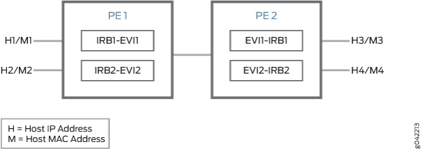
The inter-subnet traffic forwarding is performed as follows:
PE2 advertises H3-M3 and H4-M4 binding to PE1. Similarly PE1 advertises H1-M1 and H2-M2 binding to PE2.
PE1 and PE2 install the MAC address in the corresponding EVI MAC table, whereas the IP routes are installed in the shared VRF.
The advertising PE device is set as the next hop for the IP routes.
If H1 sends packets to H4, the packets are sent to IRB1 on PE1.
IP lookup for H4 happens in the shared VRF on PE1. Because the next hop for the H4 IP is PE2 (the advertising PE), an IP unicast packet is sent to PE2.
PE1 rewrites the MAC header based on the information in the VRF route, and PE2 performs a MAC lookup to forward the packet to H4.
Benefits of Implementing the EVPN IRB Solution
The main goal of the EVPN IRB solution is to provide optimal Layer 2 and Layer 3 forwarding. The solution is required to efficiently handle inter-subnet forwarding as well as virtual machine (VM) mobility. VM mobility refers to the ability of a VM to migrate from one server to another within the same or a different data center while retaining its existing MAC and IP address. Providing optimal forwarding for inter-subnet traffic and effective VM mobility involves solving two problems – the default gateway problem and the triangular routing problem.
IPv6 addresses are supported on IRB interfaces with EVPN using the Neighbor Discovery Protocol (NDP). The following capabilities are introduced for IPv6 support with EVPN:
IPv6 addresses on IRB interfaces in primary routing instances
Learning IPv6 neighborhood from solicited NA message
NS and NA packets on the IRB interfaces are disabled from network core
Virtual gateway addresses are used as Layer 3 addresses
Host MAC-IP synchronization for IPv6
You can configure the IPv6 addresses in the IRB interface at
the [edit interfaces irb] hierarchy level.
Gateway MAC and IP Synchronization
In an EVPN IRB deployment, the IP default gateway for a VM is the IP address configured on the IRB interface of the provider edge (PE) router corresponding to the bridge domain or VLAN of which the VM is a member. The default gateway problem arises because a VM does not flush its ARP table when relocating from one server to another and continues sending packets with the destination MAC address set to that of the original gateway. If the old and new servers are not part of the same Layer 2 domain (the new Layer 2 domain could be within the current data center or a new data center), the gateway previously identified is no longer the optimal or local gateway. The new gateway needs to identify packets containing the MAC addresses of other gateways on remote PE routers and forward the traffic as if the packets were destined to the local gateway itself. At the minimum, this functionality requires each PE router to advertise its gateway or IRB MAC and IP addresses to all other PE routers in the network. The gateway address exchange can be accomplished using the standard MAC route advertisement message (including the IP address parameter) and tagging that route with the default gateway extended community so that the remote PE routers can distinguish the gateway MAC advertisement routes from normal MAC advertisement routes.
We require that you configure the no-gateway-community
option at the [edit routing-instances
EVPN-instance-name protocols evpn
default-gateway] hierarchy level in each EVPN routing instance
in which you configure an IRB interface with a virtual gateway address.
On platforms that support configuring the
no-gateway-community option at the global level, you
can alternatively configure no-gateway-community at the
[edit protocols evpn default-gateway] hierarchy level.
See default-gateway for details on using the
no-gateway-community option.
Layer 3 VPN Interworking
The inter-data center aspect of the EVPN IRB solution involves routing between VMs that are present in different data centers or routing between a host site completely outside of the data center environment and a VM within a data center. This solution relies on the ability of EVPN MAC route advertisements to carry both MAC address and IP address information. The local MAC learning functionality of the PE router is extended to also capture IP address information associated with MAC addresses learned locally. That IP-MAC address mapping information is then distributed to each PE router through normal EVPN procedures. When a PE router receives such MAC and IP information, it installs the MAC route in the EVPN instance as well as a host route for the associated IP address in the Layer 3 VPN VRF corresponding to that EVPN instance. When a VM moves from one data center to another, normal EVPN procedures result in the MAC and IP address being advertised from the new PE router which the VM resides behind. The host route installed in the VRF associated with an EVPN solicits Layer 3 traffic destined to that VM to the new PE router and avoids triangular routing between the source, the former PE router the VM resided behind, and the new PE router.
BGP scalability is a potential concern with the inter-data center triangular routing avoidance solution because of the potential for injection of many host routes into Layer 3 VPN. With the method previously described, in the worst case there is an IP host route for each MAC address learned through the local EVPN MAC learning procedures or through a MAC advertisement message received from a remote PE router. BGP route target filtering can be used to limit distribution of such routes.
The following functional elements are required to implement the inter-data center triangular routing avoidance using Layer 3 inter-subnet forwarding procedures:
The source host sends an IP packet using its own source MAC and IP address with the destination MAC of the IRB interface of the local PE router and the IP address of the destination host.
When the IRB interface receives the frame with its MAC as the destination, it performs a Layer 3 lookup in the VRF associated with the EVPN instance to determine where to route the packet.
In the VRF, the PE router finds the Layer 3 route derived from a MAC plus an IP EVPN route received from the remote PE router earlier. The destination MAC address is then changed to the destination MAC address corresponding to the destination IP.
The packet is then forwarded to the remote PE router serving the destination host using MPLS, using the label corresponding to the EVPN instance of which the destination host is a member.
The egress PE router receiving the packet performs a Layer 2 lookup for the destination host’s MAC and sends the packet to the destination host on the attached subnet via the egress PE router’s IRB interface.
Because the ingress PE router is performing Layer 3 routing, the IP TTL is decremented.
See Also
Example: Configuring EVPN-MPLS with IRB Solution
This example shows how to configure an integrated routing and bridging (IRB) solution in an Ethernet VPN (EVPN) deployment.
Requirements
This example uses the following hardware and software components:
-
Two MX Series Routing Platforms as PE routers.
-
Two customer edge (CE) routers, each connected to the PE routers.
-
Junos OS Release 14.1 or later running on all the PE routers.
-
Updated and re-validated using Junos OS Release 22.1R1.
-
Before you begin:
-
Configure the router interfaces.
-
Configure OSPF or any other IGP protocol.
-
Configure BGP.
-
Configure RSVP or LDP.
-
Configure MPLS.
Overview
In an EVPN solution, multiple bridge domains can be defined within a particular EVPN instance, and one or more EVPN instances can be associated with a single Layer 3 VPN VRF. In general, each data center tenant is assigned a unique Layer 3 VPN virtual route forwarding (VRF), although the tenant can be comprised of one or more EVPN instances or bridge domains per EVPN instance.
To support this flexibility and scalability factor, the EVPN solution provides support for the IRB interfaces on MX Series routers containing MPC FPCs to facilitate optimal Layer 2 and Layer 3 forwarding along with virtual machine mobility. The IRB interfaces are configured on each configured bridge domain including the default bridge domain for an EVPN instance.
IRB is the ability to do Layer 2 switching and Layer 3 routing within a single node, thus avoiding extra hops for inter-subnet traffic. The EVPN IRB solution eliminates the default gateway problem using the gateway MAC and IP synchronization, and avoids the triangular routing problem with Layer 3 interworking by creating IP host routes for virtual machines (VMs) in the tenant VRFs.
Topology
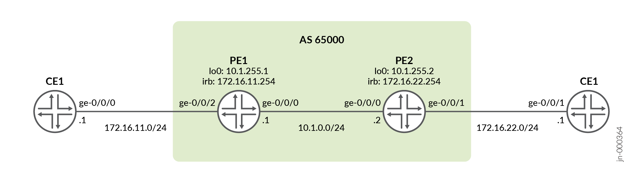
Figure 2 illustrates a simple EVPN topology with IRB solution. Routers PE1 and PE2 are the provider edge routers that connect to two customer edge (CE) routers each – CE1 and CE2.
Configuration
Procedure
CLI Quick Configuration
To quickly configure this example, copy the following commands, paste them
into a text file, remove any line breaks, change any details necessary to
match your network configuration, and then copy and paste the commands into
the CLI at the [edit] hierarchy level.
CE1
set interfaces ge-0/0/0 vlan-tagging
set interfaces ge-0/0/0 unit 0 vlan-id 10
set interfaces ge-0/0/0 unit 0 family inet address 172.16.11.1/24
set routing-options static route 172.16.22.0/24 next-hop 172.16.11.254
PE1
set interfaces ge-0/0/0 unit 0 family inet address 10.1.0.1/24
set interfaces ge-0/0/0 unit 0 family mpls
set interfaces ge-0/0/2 flexible-vlan-tagging
set interfaces ge-0/0/2 encapsulation flexible-ethernet-services
set interfaces ge-0/0/2 unit 0 encapsulation vlan-bridge
set interfaces ge-0/0/2 unit 0 vlan-id 10
set interfaces irb unit 0 family inet address 172.16.11.254/24
set interfaces lo0 unit 0 family inet address 10.1.255.1/32
set routing-instances evpna instance-type evpn
set routing-instances evpna protocols evpn interface ge-0/0/2.0
set routing-instances evpna vlan-id 10
set routing-instances evpna routing-interface irb.0
set routing-instances evpna interface ge-0/0/2.0
set routing-instances evpna route-distinguisher 10.1.255.1:1
set routing-instances evpna vrf-target target:65000:1
set routing-instances vrf instance-type vrf
set routing-instances vrf interface irb.0
set routing-instances vrf route-distinguisher 10.1.255.1:10
set routing-instances vrf vrf-target target:65000:10
set routing-instances vrf vrf-table-label
set routing-options router-id 10.1.255.1
set routing-options autonomous-system 65000
set routing-options forwarding-table chained-composite-next-hop ingress evpn
set protocols bgp group ibgp type internal
set protocols bgp group ibgp local-address 10.1.255.1
set protocols bgp group ibgp family inet-vpn unicast
set protocols bgp group ibgp family evpn signaling
set protocols bgp group ibgp neighbor 10.1.255.2
set protocols mpls label-switched-path PE1-to-PE2 from 10.1.255.1
set protocols mpls label-switched-path PE1-to-PE2 to 10.1.255.2
set protocols mpls interface all
set protocols mpls interface fxp0.0 disable
set protocols ospf traffic-engineering
set protocols ospf area 0.0.0.0 interface all
set protocols ospf area 0.0.0.0 interface fxp0.0 disable
set protocols rsvp interface all
set protocols rsvp interface fxp0.0 disable
PE2
set interfaces ge-0/0/0 unit 0 family inet address 10.1.0.2/24
set interfaces ge-0/0/0 unit 0 family mpls
set interfaces ge-0/0/1 flexible-vlan-tagging
set interfaces ge-0/0/1 encapsulation flexible-ethernet-services
set interfaces ge-0/0/1 unit 0 encapsulation vlan-bridge
set interfaces ge-0/0/1 unit 0 vlan-id 20
set interfaces irb unit 0 family inet address 172.16.22.254/24
set interfaces lo0 unit 0 family inet address 10.1.255.2/32
set routing-instances evpna instance-type evpn
set routing-instances evpna protocols evpn interface ge-0/0/1.0
set routing-instances evpna vlan-id 20
set routing-instances evpna routing-interface irb.0
set routing-instances evpna interface ge-0/0/1.0
set routing-instances evpna route-distinguisher 10.1.255.2:1
set routing-instances evpna vrf-target target:65000:1
set routing-instances vrf instance-type vrf
set routing-instances vrf interface irb.0
set routing-instances vrf route-distinguisher 10.1.255.2:10
set routing-instances vrf vrf-target target:65000:10
set routing-instances vrf vrf-table-label
set routing-options router-id 10.1.255.2
set routing-options autonomous-system 65000
set routing-options forwarding-table chained-composite-next-hop ingress evpn
set protocols bgp group ibgp type internal
set protocols bgp group ibgp local-address 10.1.255.2
set protocols bgp group ibgp family inet-vpn unicast
set protocols bgp group ibgp family evpn signaling
set protocols bgp group ibgp neighbor 10.1.255.1
set protocols mpls label-switched-path PE2-to-PE1 from 10.1.255.2
set protocols mpls label-switched-path PE2-to-PE1 to 10.1.255.1
set protocols mpls interface all
set protocols mpls interface fxp0.0 disable
set protocols ospf traffic-engineering
set protocols ospf area 0.0.0.0 interface all
set protocols ospf area 0.0.0.0 interface fxp0.0 disable
set protocols rsvp interface all
set protocols rsvp interface fxp0.0 disable
CE2
set interfaces ge-0/0/1 vlan-tagging
set interfaces ge-0/0/1 unit 0 vlan-id 20
set interfaces ge-0/0/1 unit 0 family inet address 172.16.22.1/24
set routing-options static route 172.16.11.0/24 next-hop 172.16.22.254
Step-by-Step Procedure
The following example requires you to navigate various levels in the configuration hierarchy. For information about navigating the CLI, see Use the CLI Editor in Configuration Mode.
To configure PE1:
Repeat this procedure for PE2, after modifying the appropriate interface names, addresses, and other parameters.
-
Configure the interfaces on PE1.
user@PE1# set interfaces ge-0/0/0 unit 0 family inet address 10.1.0.1/24
user@PE1# set interfaces ge-0/0/0 unit 0 family mpls
user@PE1# set interfaces ge-0/0/2 flexible-vlan-tagging
user@PE1# set interfaces ge-0/0/2 encapsulation flexible-ethernet-services
user@PE1# set interfaces ge-0/0/2 unit 0 encapsulation vlan-bridge
user@PE1# set interfaces ge-0/0/2 unit 0 vlan-id 10
user@PE1# set interfaces irb unit 0 family inet address 172.16.11.254/24
user@PE1# set interfaces lo0 unit 0 family inet address 10.1.255.1/32
-
Set the router ID and autonomous system number for PE1.
user@PE1# set routing-options router-id 10.1.255.1
user@PE1# set routing-options autonomous-system 65000
-
Configure the chained composite next hop for EVPN.
user@PE1# set routing-options forwarding-table chained-composite-next-hop ingress evpn
-
Enable RSVP on all the interfaces of PE1, excluding the management interface.
user@PE1# set protocols rsvp interface all
user@PE1# set protocols rsvp interface fxp0.0 disable
-
Enable MPLS on all the interfaces of PE1, excluding the management interface. Create a label-switched path from PE1 to PE2.
user@PE1# set protocols mpls label-switched-path PE1-to-PE2 from 10.1.255.1
user@PE1# set protocols mpls label-switched-path PE1-to-PE2 to 10.1.255.2
user@PE1# set protocols mpls interface all
user@PE1# set protocols mpls interface fxp0.0 disable
-
Configure the BGP group for IBGP on PE1. Assign local and neighbor addresses for PE1 to peer with PE2 using the loopback address. Include the family
inet-vpn unicastandevpn signalingfor Network Layer Reachability Information (NLRI).user@PE1# set protocols bgp group ibgp type internal user@PE1# set protocols bgp group ibgp local-address 10.1.255.1 user@PE1# set protocols bgp group ibgp family inet-vpn unicast user@PE1# set protocols bgp group ibgp family evpn signaling user@PE1# set protocols bgp group ibgp neighbor 10.1.255.2
-
Configure OSPF on all the interfaces of PE1, excluding the management interface. Enable traffic-engineering for OSPF. For RSVP-signaled LSPs with OSPF as the IGP, traffic-engineering must be enabled for the LSPs to come up.
user@PE1# set protocols ospf traffic-engineering
user@PE1# set protocols ospf area 0.0.0.0 interface all
user@PE1# set protocols ospf area 0.0.0.0 interface fxp0.0 disable
-
Configure the EVPN routing instance. Configure the VLAN identifier, the interface connected to CE1, the IRB interface as a routing interface, the route distinguisher, and the VRF target for the evpna routing instance.
user@PE1#set routing-instances evpna instance-type evpn
user@PE1#set routing-instances evpna protocols evpn interface ge-0/0/2.0
user@PE1#set routing-instances evpna vlan-id 10
user@PE1#set routing-instances evpna routing-interface irb.0
user@PE1#set routing-instances evpna interface ge-0/0/2.0
user@PE1#set routing-instances evpna route-distinguisher 10.1.255.1:1
user@PE1#set routing-instances evpna vrf-target target:65000:1
-
Configure the VRF routing instance. Configure the IRB interface, the route distinguisher, the VRF target, and the VRF table label for the vrf routing instance.
user@PE1# set routing-instances vrf instance-type vrf
user@PE1# set routing-instances vrf interface irb.0
user@PE1# set routing-instances vrf route-distinguisher 10.1.255.1:10
user@PE1# set routing-instances vrf vrf-target target:65000:10
user@PE1# set routing-instances vrf vrf-table-label
Results
From configuration mode, confirm your configuration by entering the show
interfaces, show routing-options, show
protocols, and show routing-instances commands. If
the output does not display the intended configuration, repeat the instructions
in this example to correct the configuration.
user@PE1# show interfaces
ge-0/0/0 {
    unit 0 {
        family inet {
            address 10.1.0.1/24;
        }
        family mpls;
    }
}
ge-0/0/2 {
    flexible-vlan-tagging;
    encapsulation flexible-ethernet-services;
    unit 0 {
        encapsulation vlan-bridge;
        vlan-id 10;
    }
}
irb {
    unit 0 {
        family inet {
            address 172.16.11.254/24;
        }
    }
}
lo0 {
    unit 0 {
        family inet {
            address 10.1.255.1/32;
        }
    }
}user@PE1# show routing-options
router-id 10.1.255.1;
autonomous-system 65000;
forwarding-table {
chained-composite-next-hop {
ingress {
evpn;
}
}
}user@PE1# show protocols
bgp {
group ibgp {
type internal;
local-address 10.1.255.1;
family inet-vpn {
unicast;
}
family evpn {
signaling;
}
neighbor 10.1.255.2;
}
}
mpls {
label-switched-path PE1-to-PE2 {
from 10.1.255.1;
to 10.1.255.2;
}
interface all;
interface fxp0.0 {
disable;
}
}
ospf {
traffic-engineering;
area 0.0.0.0 {
interface all;
interface fxp0.0 {
disable;
}
}
}
rsvp {
interface all;
interface fxp0.0 {
disable;
}
}user@PE1# show routing-instances
evpna {
instance-type evpn;
protocols {
evpn {
interface ge-0/0/2.0;
}
}
vlan-id 10;
routing-interface irb.0;
interface ge-0/0/2.0;
route-distinguisher 10.1.255.1:1;
vrf-target target:65000:1;
}
vrf {
instance-type vrf;
interface irb.0;
route-distinguisher 10.1.255.1:10;
vrf-target target:65000:10;
vrf-table-label;
}Verification
Confirm that the configuration is working properly.
- Verifying Local IRB MACs
- Verifying Remote IRB MACs
- Verifying Local IRB IPs
- Verifying Remote IRB IPs
- Verifying CE-CE Reachability
- Verifying CE-PE Reachability
- Verifying PE-PE Reachability
Verifying Local IRB MACs
Purpose
Verify that the local IRB MACs are learned from L2ALD.
Action
On PE1, determine the MAC address of the local IRB interface.
From operational mode, run the show interfaces irb extensive | match
"Current address" command.
user@PE1> show interfaces irb extensive | match "Current address"
  Current address: 2c:6b:f5:1b:46:f0, Hardware address: 2c:6b:f5:1b:46:f0
From operational mode, run the show route table evpna.evpn.0
extensive | find 2c:6b:f5:1b:46:f0 command.
user@PE1> show route table evpna.evpn.0 extensive | find 2c:6b:f5:1b:46:f0
2:10.1.255.1:1::10::2c:6b:f5:1b:46:f0/304 MAC/IP (1 entry, 1 announced)
        *EVPN   Preference: 170
                Next hop type: Indirect, Next hop index: 0
                Address: 0x7a18b78
                Next-hop reference count: 12, key opaque handle: 0x0
                Protocol next hop: 10.1.255.1
                Indirect next hop: 0x0 - INH Session ID: 0
                State: <Active Int Ext>
                Age: 1:34:57
                Validation State: unverified
                Task: evpna-evpn
                Announcement bits (1): 2-rt-export
                AS path: I
                Communities: evpn-default-gateway
                Route Label: 299936
                ESI: 00:00:00:00:00:00:00:00:00:00
                Thread: junos-main
Meaning
The route for the local IRB interface appears in the EVPN instance route table on PE1 and is learned from EVPN and tagged with the default gateway extended community.
Verifying Remote IRB MACs
Purpose
Verify that the remote IRB MACs are learned from BGP.
Action
On PE2, verify that the remote IRB MAC from PE1 is learned.
From operational mode, run the same show route table evpna.evpn.0
extensive | find 2c:6b:f5:1b:46:f0 command that was run on
PE1.
user@PE2> show route table evpna.evpn.0 extensive | find 2c:6b:f5:1b:46:f0
2:10.1.255.1:1::10::2c:6b:f5:1b:46:f0/304 MAC/IP (1 entry, 1 announced)
        *BGP    Preference: 170/-101
                Route Distinguisher: 10.1.255.1:1
                Next hop type: Indirect, Next hop index: 0
                Address: 0x7a19160
                Next-hop reference count: 10, key opaque handle: 0x0
                Source: 10.1.255.1
                Protocol next hop: 10.1.255.1
                Indirect next hop: 0x2 no-forward INH Session ID: 0
                State: <Secondary Active Int Ext>
                Local AS: 65000 Peer AS: 65000
                Age: 1:41:11    Metric2: 1
                Validation State: unverified
                Task: BGP_65000.10.1.255.1
                Announcement bits (1): 0-evpna-evpn
                AS path: I
                Communities: target:65000:1 evpn-default-gateway
                Import Accepted
                Route Label: 299936
                ESI: 00:00:00:00:00:00:00:00:00:00
                Localpref: 100
                Router ID: 10.1.255.1
                Primary Routing Table: bgp.evpn.0
                Thread: junos-main
                Indirect next hops: 1
                        Protocol next hop: 10.1.255.1 Metric: 1
                        Indirect next hop: 0x2 no-forward INH Session ID: 0
                        Indirect path forwarding next hops: 1
                                Next hop type: Router
                                Next hop: 10.1.0.1 via ge-0/0/0.0
                                Session Id: 0
                                10.1.255.1/32 Originating RIB: inet.3
                                  Metric: 1 Node path count: 1
                                  Forwarding nexthops: 1
                                        Next hop type: Router
                                        Next hop: 10.1.0.1 via ge-0/0/0.0
                                        Session Id: 0
Meaning
The route for the remote IRB interface appears in the EVPN instance route table on PE2. The route is learned from BGP and tagged with the default gateway extended community.
Verifying Local IRB IPs
Purpose
Verify that the local IRB IPs are learned locally by RPD.
Action
On PE1, determine the MAC and IP addresses of the local IRB interface.
From operational mode, run the show interfaces irb extensive | match
"Current address" command.
user@PE1> show interfaces irb extensive | match "Current address"
  Current address: 2c:6b:f5:1b:46:f0, Hardware address: 2c:6b:f5:1b:46:f0
From operational mode, run the show interfaces irb.0 terse | match
inet command.
user@PE1> show interfaces irb.0 terse | match inet
irb.0                   up    up   inet     172.16.11.254/24
From operational mode, run the show route table evpna.evpn.0
extensive | find "a8:d0:e5:54:0d:10::10.0.0.251" command.
user@PE1> show route table evpna.evpn.0 extensive | find 2c:6b:f5:1b:46:f0::172.16.11.254
2:10.1.255.1:1::10::2c:6b:f5:1b:46:f0::172.16.11.254/304 MAC/IP (1 entry, 1 announced)
        *EVPN   Preference: 170
                Next hop type: Indirect, Next hop index: 0
                Address: 0x7a18b78
                Next-hop reference count: 12, key opaque handle: 0x0
                Protocol next hop: 10.1.255.1
                Indirect next hop: 0x0 - INH Session ID: 0
                State: <Active Int Ext>
                Age: 2:12:19
                Validation State: unverified
                Task: evpna-evpn
                Announcement bits (1): 2-rt-export
                AS path: I
                Communities: evpn-default-gateway
                Route Label: 299936
                ESI: 00:00:00:00:00:00:00:00:00:00
                Thread: junos-main
Meaning
The MAC plus IP route for the local IRB interface appears in the EVPN instance route table on PE1 and is learned from EVPN and tagged with the default gateway extended community.
Verifying Remote IRB IPs
Purpose
Verify that the remote IRB IP is learned from BGP.
Action
On Router PE2, verify that the remote IRB MAC from PE1 is learned.
From operational mode, run the same show route table evpna.evpn.0
extensive | find 2c:6b:f5:1b:46:f0::172.16.11.254 command that
was run on PE1.
user@PE2> show route table evpna.evpn.0 extensive | find 2c:6b:f5:1b:46:f0::172.16.11.254
2:10.1.255.1:1::10::2c:6b:f5:1b:46:f0::172.16.11.254/304 MAC/IP (1 entry, 1 announced)
        *BGP    Preference: 170/-101
                Route Distinguisher: 10.1.255.1:1
                Next hop type: Indirect, Next hop index: 0
                Address: 0x7a19160
                Next-hop reference count: 10, key opaque handle: 0x0
                Source: 10.1.255.1
                Protocol next hop: 10.1.255.1
                Indirect next hop: 0x2 no-forward INH Session ID: 0
                State: <Secondary Active Int Ext>
                Local AS: 65000 Peer AS: 65000
                Age: 2:13:11    Metric2: 1
                Validation State: unverified
                Task: BGP_65000.10.1.255.1
                Announcement bits (1): 0-evpna-evpn
                AS path: I
                Communities: target:65000:1 evpn-default-gateway
                Import Accepted
                Route Label: 299936
                ESI: 00:00:00:00:00:00:00:00:00:00
                Localpref: 100
                Router ID: 10.1.255.1
                Primary Routing Table: bgp.evpn.0
                Thread: junos-main
                Indirect next hops: 1
                        Protocol next hop: 10.1.255.1 Metric: 1
                        Indirect next hop: 0x2 no-forward INH Session ID: 0
                        Indirect path forwarding next hops: 1
                                Next hop type: Router
                                Next hop: 10.1.0.1 via ge-0/0/0.0
                                Session Id: 0
                                10.1.255.1/32 Originating RIB: inet.3
                                  Metric: 1 Node path count: 1
                                  Forwarding nexthops: 1
                                        Next hop type: Router
                                        Next hop: 10.1.0.1 via ge-0/0/0.0
                                        Session Id: 0
Meaning
The MAC plus IP route for the remote IRB interface appears in the EVPN instance route table on PE2 and is tagged with the default gateway extended community.
Verifying CE-CE Reachability
Purpose
Verify CE1 can ping CE2.
Action
From operational mode, run the show route 172.16.22.1
command on CE1 to ping CE2.
user@CE1> show route 172.16.22.1

inet.0: 9 destinations, 9 routes (9 active, 0 holddown, 0 hidden)
+ = Active Route, - = Last Active, * = Both

172.16.22.0/24     *[Static/5] 02:28:23
                    >  to 172.16.11.254 via ge-0/0/0.0
From operational mode, run the ping command on CE1 to ping
CE2.
user@CE1> ping 172.16.22.1 count 2
PING 172.16.22.1 (172.16.22.1): 56 data bytes
64 bytes from 172.16.22.1: icmp_seq=0 ttl=62 time=4.890 ms
64 bytes from 172.16.22.1: icmp_seq=1 ttl=62 time=4.658 ms

--- 172.16.22.1 ping statistics ---
2 packets transmitted, 2 packets received, 0% packet loss
round-trip min/avg/max/stddev = 4.658/4.774/4.890/0.116 ms
Meaning
Ping from CE1 to CE2 is successful.
Verifying CE-PE Reachability
Purpose
Verify CE1 can ping PE2.
Action
From operational mode, run the show route table vrf.inet.0
command on PE2.
user@PE2> show route table vrf.inet.0

vrf.inet.0: 5 destinations, 5 routes (5 active, 0 holddown, 0 hidden)
+ = Active Route, - = Last Active, * = Both

172.16.11.0/24     *[BGP/170] 02:27:44, localpref 100, from 10.1.255.1
                      AS path: I, validation-state: unverified
                    >  to 10.1.0.1 via ge-0/0/0.0, label-switched-path PE2-to-PE1
172.16.11.1/32     *[BGP/170] 02:27:44, localpref 100, from 10.1.255.1
                      AS path: I, validation-state: unverified
                    >  to 10.1.0.1 via ge-0/0/0.0, label-switched-path PE2-to-PE1
172.16.22.0/24     *[Direct/0] 02:28:14
                    >  via irb.0
172.16.22.1/32     *[EVPN/7] 02:24:44
                    >  via irb.0
172.16.22.254/32   *[Local/0] 02:28:14
                       Local via irb.0
From operational mode, run the ping command on CE1 to ping
the IRB interface on PE2.
user@CE1> ping 172.16.22.254 count 2
PING 172.16.22.254 (172.16.22.254): 56 data bytes
64 bytes from 172.16.22.254: icmp_seq=0 ttl=63 time=3.662 ms
64 bytes from 172.16.22.254: icmp_seq=1 ttl=63 time=2.766 ms

--- 172.16.22.254 ping statistics ---
2 packets transmitted, 2 packets received, 0% packet loss
round-trip min/avg/max/stddev = 2.766/3.214/3.662/0.448 ms
Meaning
Ping from CE1 to PE2 is successful.
Verifying PE-PE Reachability
Purpose
Verify PE1 can ping PE2.
Action
From operational mode, run the show route table vrf.inet.0
command on PE1.
user@PE1> show route table vrf.inet.0

vrf.inet.0: 5 destinations, 5 routes (5 active, 0 holddown, 0 hidden)
+ = Active Route, - = Last Active, * = Both

172.16.11.0/24     *[Direct/0] 02:40:42
                    >  via irb.0
172.16.11.1/32     *[EVPN/7] 02:37:42
                    >  via irb.0
172.16.11.254/32   *[Local/0] 02:40:42
                       Local via irb.0
172.16.22.0/24     *[BGP/170] 02:35:48, localpref 100, from 10.1.255.2
                      AS path: I, validation-state: unverified
                    >  to 10.1.0.2 via ge-0/0/0.0, label-switched-path PE1-to-PE2
172.16.22.1/32     *[BGP/170] 02:32:46, localpref 100, from 10.1.255.2
                      AS path: I, validation-state: unverified
                    >  to 10.1.0.2 via ge-0/0/0.0, label-switched-path PE1-to-PE2
From operational mode, run the ping command from PE1 to ping
the IRB interface on PE2.
user@PE1> ping 172.16.22.254 routing-instance vrf count 2
PING 172.16.22.254 (172.16.22.254): 56 data bytes
64 bytes from 172.16.22.254: icmp_seq=0 ttl=64 time=1.946 ms
64 bytes from 172.16.22.254: icmp_seq=1 ttl=64 time=2.151 ms

--- 172.16.22.254 ping statistics ---
2 packets transmitted, 2 packets received, 0% packet loss
round-trip min/avg/max/stddev = 1.946/2.048/2.151/0.102 ms
Meaning
Ping from PE1 to PE2 is successful.