IP Address Sweep and Port Scan
An address sweep occurs when one source IP address sends a predefined number of ICMP packets to various hosts within a predefined interval of time. Port scanning occurs when one source IP address sends IP packets containing TCP SYN segments to a predefined number of different ports at the same destination IP address within a predefined time interval, For more information, see the following topics:
Understanding Network Reconnaissance Using IP Options
The IP standard RFC 791, Internet Protocol, specifies a set of options for providing special routing controls, diagnostic tools, and security.
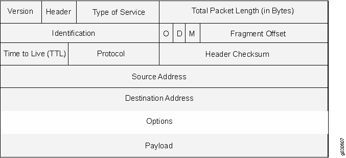
RFC 791 states that these options are “unnecessary for the most common communications” and, in reality, they rarely appear in IP packet headers. These options appear after the destination address in an IP packet header, as shown in Figure 1. When they do appear, they are frequently being put to some illegitimate use.

This topic contains the following sections:
Uses for IP Packet Header Options
Table 1 lists the IP options and their accompanying attributes.
|
Type |
Class |
Number |
Length |
Intended Use |
Nefarious Use |
|---|---|---|---|---|---|
|
End of Options |
0* |
0 |
0 |
Indicates the end of one or more IP options. |
None. |
|
No Options |
0 |
1 |
0 |
Indicates there are no IP options in the header. |
None. |
|
Security |
0 |
2 |
11 bits |
Provides a way for hosts to send security, TCC (closed user group) parameters, and Handling Restriction Codes compatible with Department of Defense (DoD) requirements. (This option, as specified in RFC 791, Internet Protocol, and RFC 1038, Revised IP Security Option, is obsolete.) Currently, this screen option is applicable only to IPv4. |
Unknown. However, because it is obsolete, its presence in an IP header is suspect. |
|
Loose Source Route |
0 |
3 |
Varies |
Specifies a partial route list for a packet to take on its journey from source to destination. The packet must proceed in the order of addresses specified, but it is allowed to pass through other devices in between those specified. |
Evasion. The attacker can use the specified routes to hide the true source of a packet or to gain access to a protected network. |
|
Record Route |
0 |
7 |
Varies |
Records the IP addresses of the network devices along the path that the IP packet travels. The destination machine can then extract and process the route information. (Due to the size limitation of 40 bytes for both the option and storage space, this can only record up to 9 IP addresses.) Currently, this screen option is applicable only to IPv4. |
Reconnaissance. If the destination host is a compromised machine in the attacker's control, he or she can glean information about the topology and addressing scheme of the network through which the packet passed. |
|
Stream ID |
0 |
8 |
4 bits |
(Obsolete) Provided a way for the 16-bit SATNET stream identifier to be carried through networks that did not support the stream concept. Currently, this screen option is applicable only to IPv4. |
Unknown. However, because it is obsolete, its presence in an IP header is suspect. |
|
Strict Source Route |
0 |
9 |
Varies |
Specifies the complete route list for a packet to take on its journey from source to destination. The last address in the list replaces the address in the destination field. Currently, this screen option is applicable only to IPv4. |
Evasion. An attacker can use the specified routes to hide the true source of a packet or to gain access to a protected network. |
|
Timestamp |
2** |
4 |
|
Records the time (in coordinated universal time [UTC]***) when each network device receives the packet during its trip from the point of origin to its destination. The network devices are identified by IP address. This option develops a list of IP addresses of the devices along the path of the packet and the duration of transmission between each one. Currently, this screen option is applicable only to IPv4. |
Reconnaissance. If the destination host is a compromised machine in the attacker's control, he or she can glean information about the topology and addressing scheme of the network through which the packet has passed. |
|
* The class of options identified as 0 was designed to provide extra packet or network control. ** The class of options identified as 2 was designed for diagnostics, debugging, and measurement. *** The timestamp uses the number of milliseconds since midnight UTC. UTC is also known as Greenwich Mean Time (GMT), which is the basis for the international time standard. |
|||||
Screen Options for Detecting IP Options Used for Reconnaissance
The following screen options detect IP options that an attacker can use for reconnaissance or for some unknown but suspect purpose:
-
Record Route—Junos OS detects packets where the IP option is 7 (record route) and records the event in the screen counters list for the ingress interface. Currently, this screen option is applicable only to IPv4.
-
Timestamp—Junos OS detects packets where the IP option list includes option 4 (Internet timestamp) and records the event in the screen counters list for the ingress interface. Currently, this screen option is applicable only to IPv4.
-
Security—Junos OS detects packets where the IP option is 2 (security) and records the event in the screen counters list for the ingress interface. Currently, this screen option is applicable only to IPv4.
-
Stream ID—Junos OS detects packets where the IP option is 8 (stream ID) and records the event in the screen counters list for the ingress interface. Currently, this screen option is applicable only to IPv4.
If a packet with any of the previous IP options is received, Junos OS flags this as a network reconnaissance attack and records the event for the ingress interface.
Example: Detecting Packets That Use IP Screen Options for Reconnaissance
This example shows how to detect packets that use IP screen options for reconnaissance.
Requirements
Before you begin, understand how network reconnaissance works. See Understanding Network Reconnaissance Using IP Options.
Overview
RFC 791, Internet Protocol, specifies a set of options for providing special routing controls, diagnostic tools, and security. The screen options detect IP options that an attacker can use for reconnaissance, including record route, timestamp, security, and stream ID.
In this example, you configure an IP screen screen-1 and enable it in a security zone called zone-1.
You can enable only one screen in one security zone.
Topology
Configuration
Procedure
CLI Quick Configuration
To quickly detect packets with the record route, timestamp, security, and stream ID IP screen options, copy the following commands and paste them into the CLI.
[edit]
set security screen ids-option screen-1 ip record-route-option
set security screen ids-option screen-1 ip timestamp-option
set security screen ids-option screen-1 ip security-option
set security screen ids-option screen-1 ip stream-option
set security zones security-zone zone-1 screen screen-1
Step-by-Step Procedure
The following example requires you to navigate various levels in the configuration hierarchy. For instructions on how to do that, see Using the CLI Editor in Configuration Mode in the CLI User Guide.
To detect packets that use IP screen options for reconnaissance:
Configure IP screen options.
Note:Currently, these screen options support IPv4 only.
[edit security screen]
user@host# set ids-option screen-1 ip record-route-option
user@host# set ids-option screen-1 ip timestamp-option
user@host# set ids-option screen-1 ip security-option
user@host# set ids-option screen-1 ip stream-option
Enable the screen in the security zone.
[edit security zones ]
user@host# set security-zone zone-1 screen screen-1
Results
From configuration mode, confirm your configuration
by entering the show security screen command. If the output
does not display the intended configuration, repeat the configuration
instructions in this example to correct it.
[edit]
[user@host]show security screen
    ids-option screen-1 {
        ip {
            record-route-option;
            timestamp-option;
            security-option;
            stream-option;
        }
    }
[edit]
[user@host]show security zones
    zones {
        security-zone zone-1 {
            screen screen-1;
        }
    }
If you are done configuring the device, enter commit from configuration mode.
Verification
Confirm that the configuration is working properly.
Verifying the Screens in the Security Zone
Purpose
Verify that the screen is enabled in the security zone.
Action
From operational mode, enter the show security
zones command.
[edit]
user@host> show security zones

Security zone: zone-1
  Send reset for non-SYN session TCP packets: Off
  Policy configurable: Yes
  Screen: screen-1
  Interfaces bound: 1
  Interfaces:
    ge-1/0/0.0
Verifying the Security Screen Configuration
Purpose
Display the configuration information about the security screen.
Action
From operational mode, enter the show security
screen ids-option screen-name command.
[edit]
user@host> show security screen ids-option screen-1
Screen object status:

  Name                                       Value
  IP record route option                     enabled
  IP timestamp option                        enabled
  IP security option                         enabled
  IP stream option                           enabled
Understanding IP Address Sweeps
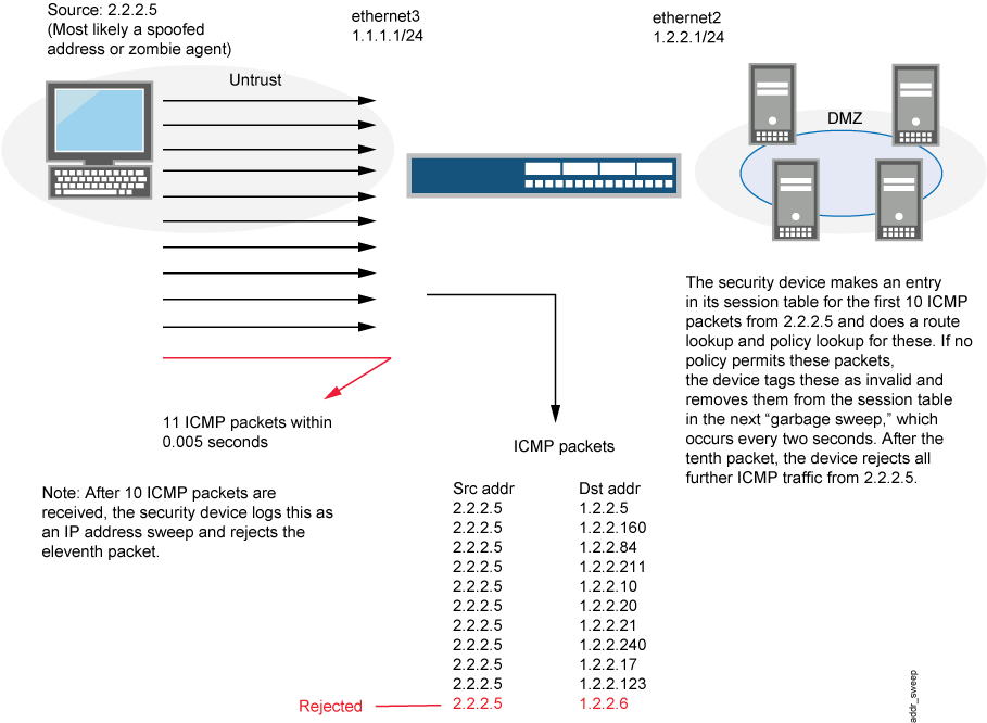
An address sweep occurs when one source IP address sends a defined number of ICMP packets sent to different hosts within a defined interval (5000 microseconds is the default). The purpose of this attack is to send ICMP packets—typically echo requests—to various hosts in the hopes that at least one replies, thus uncovering an address to target.
Junos OS internally logs the number of ICMP packets to different addresses from one remote source. Using the default settings, if a remote host sends ICMP traffic to 10 addresses in 0.005 seconds (5000 microseconds), then the device flags this as an address sweep attack and rejects all further ICMP packets from that host for the remainder of the specified threshold time period. See Figure 2.

Consider enabling this screen option for a security zone only if there is a policy permitting ICMP traffic from that zone. Otherwise, you do not need to enable the screen option. The lack of such a policy denies all ICMP traffic from that zone, precluding an attacker from successfully performing an IP address sweep anyway.
Junos OS supports this screen option for ICMPv6 trafffic also.
Example: Blocking IP Address Sweeps
This example describes how to configure a screen to block an IP address sweep originating from a security zone.
Requirements
Before you begin:
Understand how IP address sweeps work. See Understanding IP Address Sweeps.
Configure security zones. See Security Zones Overview.
Overview
You need to enable a screen for a security zone if you have configured a policy that permits ICMP traffic from that zone. If you have not configured such a policy, then your system denies all ICMP traffic from that zone, and the attacker cannot perform an IP address sweep successfully anyway.
In this example you configure a 5000-ip-sweep screen
to block IP address sweeps originating in the zone-1 security zone.
Topology
Configuration
Procedure
Step-by-Step Procedure
To configure a screen to block IP address sweeps:
Configure a screen.
[edit]
user@host# set security screen ids-option 5000-ip-sweep icmp ip-sweep threshold 5000
Enable the screen in the security zone.
[edit]
user@host# set security zones security-zone zone-1 screen 5000-ip-sweep
If you are done configuring the device, commit the configuration.
[edit]
user@host# commit
Verification
Confirm that the configuration is working properly.
Verifying the Screens in the Security Zone
Purpose
Verify that the screen is enabled in the security zone.
Action
From operational mode, enter the show security
zones command.
[edit]
user@host> show security zones
Security zone: zone-1
  Send reset for non-SYN session TCP packets: Off
  Policy configurable: Yes
  Screen: 5000-ip-sweep
   Interfaces bound: 1
  Interfaces:
    ge-1/0/0.0
Verifying the Security Screen Configuration
Purpose
Display the configuration information about the security screen.
Action
From operational mode, enter the show security
screen ids-option screen-name command.
[edit]
user@host> show security screen ids-option 5000-ip-sweep
Screen object status:

Name                                    Value
ICMP address sweep threshold            5000
Understanding TCP Port Scanning
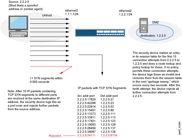
A port scan occurs when one source IP address sends IP packets containing TCP SYN segments to 10 different destination ports within a defined interval (5000 microseconds is the default). The purpose of this attack is to scan the available services in the hopes that at least one port will respond, thus identifying a service to target.
Junos OS internally logs the number of different ports scanned from one remote source. Using the default settings, if a remote host scans 10 ports in 0.005 seconds (5000 microseconds), then the device flags this as a port scan attack and rejects all further packets from the remote source, regardless of the destination IP address, for the remainder of the specified timeout period. See Figure 3.

Junos OS supports port scanning for both IPv4 and IPv6 traffic.
Understanding UDP Port Scanning
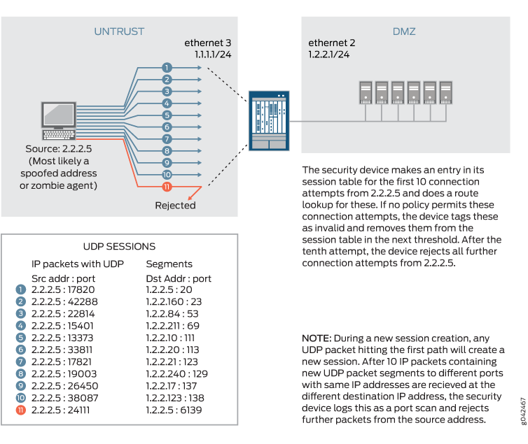
UDP port scan gives statistical information on a session threshold. As the incoming packets traverse the screen, the sessions are established. The number of sessions threshold enforced is based on zone, source IP, and the threshold period and does not allow more than 10 new sessions in the configured threshold period, for each zone and source IP address. The UDP port scan is disabled by default. When the UDP port scan is enabled, the default threshold period is 5000 microseconds. This value can be manually set to a range of 1000-1,000,000 microseconds. This feature protects some exposed public UDP services against DDoS attacks. See Figure 4.

Enhancing Traffic Management by Blocking Port Scans
This example shows how to enhance traffic management by configuring a screen to block port scans originating from a particular security zone.
Requirements
Before you begin, understand how port scanning works. See Understanding TCP Port Scanning.
Overview
You can use a port scan to block IP packets containing TCP SYN segments or UDP segments sent to different ports from the same source address within a defined interval. The purpose of this attack is to scan the available services in the hopes that at least one port will respond. Once a port responds, it is identified as a service to target.
In this example, you configure a 5000 port-scan screen to block port scans originating from a particular security zone and then assign the screen to the zone called zone-1.
Topology
Configuration
Procedure
CLI Quick Configuration
To quickly configure this example, copy the
following commands, paste them into a text file, remove any line breaks,
change any details necessary to match your network configuration,
copy and paste the commands into the CLI at the [edit] hierarchy
level, and then enter commit from configuration
mode.
set security screen ids-option 5000-port-scan tcp port-scan threshold 5000
set security screen ids-option 10000-port-scan udp port-scan threshold 10000
set security zones security-zone zone-1 screen 5000-port-scan
Step-by-Step Procedure
The following example requires you to navigate various levels in the configuration hierarchy. For instructions on how to do that, see Using the CLI Editor in Configuration Mode in the CLI User Guide.
To configure a screen to block port scans:
Configure the screen.
[edit security]
user@host# set security screen ids-option 5000-port-scan tcp port-scan threshold 5000
user@host#set security screen ids-option 10000-port-scan udp port-scan threshold 10000
Enable the screen in the security zone.
[edit security]
user@host# set security zones security-zone zone-1 screen 5000-port-scan
Results
From configuration mode, confirm your configuration
by entering the show security screen ids-option 5000-port-scan and show security zones commands. If the output does
not display the intended configuration, repeat the configuration instructions
in this example to correct it.
[edit]
user@host# show security screen ids-option 5000-port-scan
tcp {
     port-scan threshold 5000;
}
udp {
     port-scan threshold 10000;
}
[edit]
user@host# show security zones
security-zone zone-1 {
     screen 5000-port-scan;
}
If you are done configuring the device, enter commit from configuration mode.
Verification
Confirm that the configuration is working properly.
Verifying the Screens in the Security Zone
Purpose
Verify that the screen is enabled in the security zone.
Action
From operational mode, enter the show security
zones command.
[edit]
user@host> show security zones
Security zone: zone-1
  Send reset for non-SYN session TCP packets: Off
  Policy configurable: Yes
  Screen: 5000-port-scan
  Interfaces bound: 0
  Interfaces:
Meaning
The sample output shows that the screen for zone-1 is enabled for port scan blocking.
Verifying the Security Screen Configuration
Purpose
Verify the configuration information about the security screen.
Action
From operational mode, enter the show security
screen ids-option screen-name command.
[edit]
user@host> show security screen ids-option 5000-port-scan
Screen object status:
Name                                         Value
  TCP port scan threshold                    5000
  UDP port scan threshold                    10000
Meaning
The sample output shows that the port scan blocking is operational with TCP and UDP threshold.
