Understand Virtual Output Queues
This section describes the virtual output queue (VOQ) architecture.
Refer to Feature Explorer for platform and release support information for VOQs.
Introduction to Virtual Output Queues
This topic introduces the VOQ architecture and how it operates with configurable class-of-service (CoS) components.
On supported platforms, Junos hardware CoS features use virtual output queues on the ingress to buffer and queue traffic for each egress output queue. Most platforms support up to eight egress output queues per output port (physical interface).
The traditional method of forwarding traffic through a router is based on buffering ingress traffic in input queues on ingress interfaces, forwarding the traffic across the fabric to output queues on egress interfaces, and then buffering traffic again on the output queues before transmitting the traffic to the next hop. The traditional method of queueing packets on an ingress port is storing traffic destined for different egress ports in the same input queue (buffer).
During periods of congestion, the router might drop packets at the egress port, so the router might spend resources transporting traffic across the switch fabric to an egress port, only to drop that traffic instead of forwarding it. And because input queues store traffic destined for different egress ports, congestion on one egress port could affect traffic on a different egress port, a condition called head-of-line blocking (HOLB).
VOQ architecture takes a different approach:
-
Instead of separate physical buffers for input and output queues, the Junos device uses the physical buffers on the ingress pipeline of each Packet Forwarding Engine (PFE) to store traffic for every egress port. Every output queue on an egress port has buffer storage space on every ingress pipeline on all of the PFEs on the router. The mapping of ingress pipeline storage space to output queues is 1-to-1, so each output queue receives buffer space on each ingress pipeline.
-
Instead of one input queue containing traffic destined for multiple different output queues (a one-to-many mapping), each output queue has a dedicated VOQ comprised of the input buffers on each PFE that are dedicated to that output queue (a 1-to-1 mapping). This architecture prevents communication between any two ports from affecting another port.
-
Instead of storing traffic on a physical output queue until it can be forwarded, a VOQ does not transmit traffic from the ingress port across the fabric to the egress port until the egress port has the resources to forward the traffic. A VOQ is a collection of input queues (buffers) that receive and store traffic destined for one output queue on one egress port. Each output queue on each egress port has its own dedicated VOQ, which consists of all of the input queues that are sending traffic to that output queue.
A VOQ is a collection of input queues (buffers) that receive and store traffic destined for one output queue on one egress port. Each output queue on each egress port has its own dedicated VOQ, which consists of all of the input queues that are sending traffic to that output queue.
VOQ Architecture
A VOQ represents the ingress buffering for a particular output queue. Each of the PFEs uses a specific output queue. The traffic stored on the PFEs comprises the traffic destined for one particular output queue on one port, and is the VOQ for that output queue.
A VOQ is distributed across all of the PFEs in the router that are actively sending traffic to that output queue. Each output queue is the sum of the total buffers assigned to that output queue across all of the PFEs in the router. So the output queue itself is virtual, not physical, although the output queue is comprised of physical input queues.
Round-Trip Time Buffering
Although there is no output queue buffering during periods of congestion (no long-term storage), there is a small physical output queue buffer on egress line cards to accommodate the round-trip time for traffic to traverse the fabric from ingress to egress. The round-trip time consists of the time it takes the ingress port to request egress port resources, receive a grant from the egress port for resources, and transmit the data across the fabric.
That means if a packet is not dropped at the router ingress, and the router forwards the packet across the fabric to the egress port, the packet will not be dropped and will be forwarded to the next hop. All packet drops take place in the ingress pipeline.
VOQ Advantages
VOQ architecture provides two major advantages:
Eliminate Head-of-Line Blocking
VOQ architecture eliminates head-of-line blocking (HOLB) issues. On non-VOQ devices, HOLB occurs when congestion at an egress port affects a different egress port that is not congested. HOLB occurs when the congested port and the non-congested port share the same input queue on an ingress interface.
VOQ architecture avoids HOLB by creating a different dedicated virtual queue for each output queue on each interface.
Because different egress queues do not share the same input queue, a congested egress queue on one port cannot affect an egress queue on a different port. For the same reason, a congested egress queue on one port cannot affect another egress queue on the same port—each output queue has its own dedicated VOQ composed of ingress interface input queues.
Performing queue buffering at the ingress interface ensures that the router only sends traffic across the fabric to an egress queue if that egress queue is ready to receive that traffic. If the egress queue is not ready to receive traffic, the traffic remains buffered at the ingress interface.
Increase Fabric Efficiency and Utilization
Traditional output queue architecture has some inherent inefficiencies that VOQ architecture addresses.
-
Packet buffering—Traditional queueing architecture buffers each packet twice in long-term DRAM storage, once at the ingress interface and once at the egress interface. VOQ architecture buffers each packet only once in long-term DRAM storage, at the ingress interface. The fabric is fast enough to be transparent to egress CoS policies, so instead of buffering packets a second time at the egress interface, the router can forward traffic at a rate that does not require deep egress buffers, without affecting the configured egress CoS policies (scheduling).
-
Consumption of resources—Traditional queueing architecture sends packets from the ingress interface input queue (buffer), across the fabric, to the egress interface output queue (buffer). At the egress interface, packets might be dropped, even though the router has expended resources transporting the packets across the fabric and storing them in the egress queue. VOQ architecture does not send packets across the fabric to the egress interface until the egress interface is ready to transmit the traffic. This increases system utilization because no resources are wasted transporting and storing packets that are dropped later.
Does VOQ Change How I Configure CoS?
There are no changes to the way you configure the CoS features. Figure 1 shows the Junoś CoS components and VOQ selection, illustrating the sequence in which they interact.
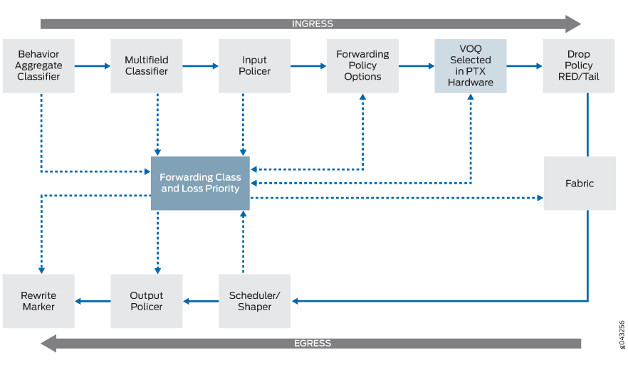
The VOQ selection process is performed by ASICs that use either the behavior aggregate (BA) classifier or the multifield classifier, depending on your configuration, to select one of the eight possible VOQs for an egress port. The VOQs on the ingress buffer data for the egress port based on your CoS configuration.
Although the CoS features do not change, there are some operational differences with VOQ:
-
Random early detection (RED) occurs on the ingress PFEs. With devices that support only egress output queuing, RED and associated congestion drops occur on the egress. Performing RED on the ingress saves valuable resources and increases router performance.
Although RED occurs on the ingress with VOQ, there is no change to how you configure the drop profiles.
-
Fabric scheduling is controlled through request and grant control messages. Packets are buffered in ingress VOQs until the egress PFE sends a grant message to the ingress PFE indicating it is ready to receive them. For details on fabric scheduling, see Fabric Scheduling and Virtual Output Queues on PTX Series Routers.
Understand How VOQs Work
This topic describes how the VOQ process works on supported Junos devices.
Understanding the Components of the VOQ Process
Figure 2 shows the hardware components of the Junos device involved in the VOQ process.
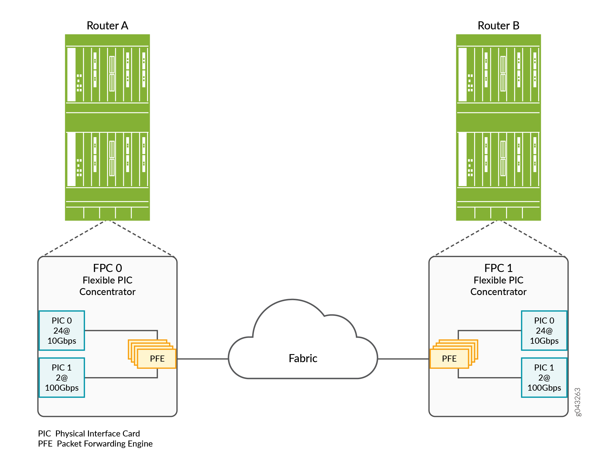
These components perform the following functions:
-
Physical Interface Card (PIC)—Provides the physical connection to various network media types, receiving incoming packets from the network and transmitting outgoing packets to the network.
-
Flexible PIC Concentrator (FPC)—Connects the PICs installed in it to the other packet transport router components.
-
Packet Forwarding Engine (PFE)—Provides L2 and L3 packet switching and encapsulation and de-encapsulation. The PFE also provides forwarding, route lookup functions, and manages packet buffering and the queuing of notifications. The PFE receives incoming packets from the PICs installed on the FPC and forwards the packets through the device planes to the appropriate destination port.
-
Output queues—(Not shown) These output queues are controlled by the CoS scheduler configuration, which establishes how to handle the traffic within the output queues for transmission onto the device fabric. In addition, these output queues control when packets are sent from the VOQs on the ingress to the egress output queues.
Understanding the VOQ Process
Output queues are controlled by the CoS scheduler configuration, which establishes how to handle the traffic within the output queues for transmission onto the fabric. In addition, these output queues control when packets are sent from the VOQs on the ingress to the egress output queues.
For every egress output queue, the VOQ architecture provides virtual queues on each and every ingress PFE. These queues are referred to as virtual because the queues physically exist on the ingress PFE only when the line card actually has packets enqueued to it.
Figure 3 shows three ingress PFEs—PFE0, PFE1, and PFE2. Each ingress PFE provides up to eight VOQs (PFEn.e0.q0 through PFEn.e0.q7) for the single egress port 0. The egress PFE (PFEn) distributes the bandwidth to each ingress VOQ in a round-robin fashion.
For example, egress PFE n's VOQ e0.q0 has 10 Gbps of bandwidth available to it. PFE 0 has an offered load 10 Gbps to e0.qo, PFE1 and PFE2 have an offered load of 1 Gbps to e0.q0. The result is that PFE1 And PFE2 will get 100 percent of their traffic through, while PFE0 will only get 80 percent of its traffic through.
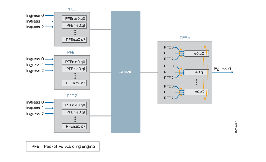
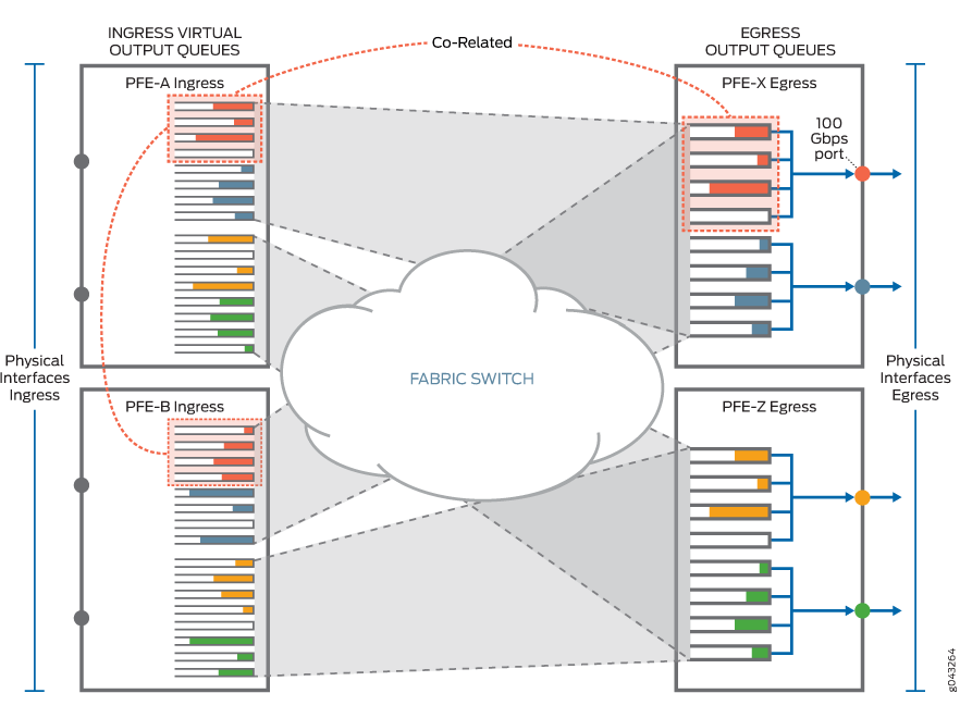
Figure 4 illustrates an example of the correlation between the egress output queues and the ingress virtual output queues. On the egress side, PFE-X has a 100 Gbps port, which is configured with four different forwarding classes. As a result, the 100 Gbps egress output port on PFE-X uses four out of eight available egress output queues (as denoted by the four queues highlighted with dashed-orange lines on PFE-X), and the VOQ architecture provides four corresponding virtual output queues on each ingress PFE (as denoted by the four virtual queues on PFE-A and PFE-B highlighted with dashed-orange lines). The virtual queues on PFE-A and PFE-B exist only when there is traffic to be sent.
Fabric Scheduling and VOQs
This topic describes the fabric scheduling process on Junos devices that use VOQs.
VOQs use request and grant messages to control fabric scheduling on Junos devices. The egress Packet Forwarding Engines control data delivery from the ingress VOQs by using request and grant messages. The virtual queues buffer packets on the ingress until the egress Packet Forwarding Engine confirms that it is ready to receive the packets by sending a grant message to the ingress Packet Forwarding Engine.
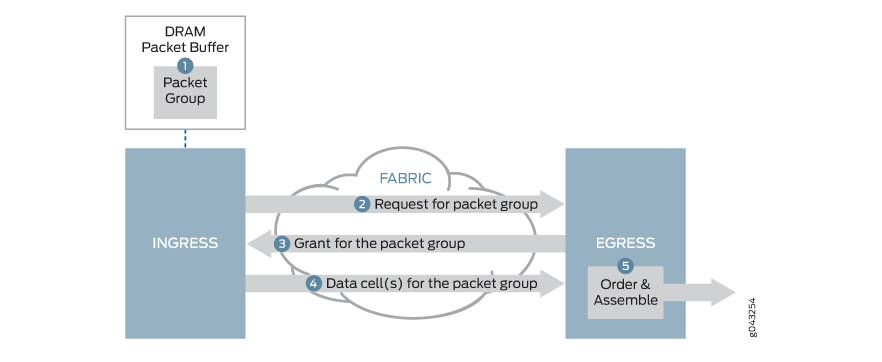
Figure 5 illustrates the fabric scheduling process used by Junos devices with VOQs. When packets arrive at an ingress port, the ingress pipeline stores the packet in the ingress queue associated with the destination output queue. The router makes the buffering decision after performing the packet lookup. If the packet belongs to a forwarding class for which the maximum traffic threshold has been exceeded, the packet might not be buffered and might be dropped. The scheduling process works as follows:
-
An ingress Packet Forwarding Engine receives a packet and buffers it in virtual queues, then groups the packet with other packets destined for the same egress interface and data output queue.
-
The ingress line card Packet Forwarding Engine sends a request, which contains a reference to the packet group, over the fabric to the egress Packet Forwarding Engine.
-
When there is available egress bandwidth, the egress line card grant scheduler responds by sending a bandwidth grant to the ingress line card Packet Forwarding Engine. .
-
When the ingress line card Packet Forwarding Engine receives the grant from the egress line card Packet Forwarding Engine, the ingress Packet Forwarding Engine segments the packet group and sends all of the pieces over the fabric to the egress Packet Forwarding Engine.
-
The egress Packet Forwarding Engine receives the pieces, reassembles the pieces into the packet group, and enqueues individual packets to a data output queue corresponding to the VOQ.
Ingress packets remain in the VOQ on the ingress port input queues until the output queue is ready to accept and forward more traffic.
Under most conditions, the fabric is fast enough to be transparent to egress CoS policies. Therefore the process of forwarding traffic from the ingress pipeline, across the fabric, to egress ports, does not affect the configured CoS policies for the traffic. The fabric only affects CoS policy if there is a fabric failure or an issue of port fairness.
When a packet ingresses and egresses the same Packet Forwarding Engine (local switching), the packet does not traverse the fabric. However, the router uses the same request and grant mechanism to receive egress bandwidth as packets that cross the fabric, so locally routed packets and packets that arrive at a Packet Forwarding Engine after crossing the fabric are treated fairly when the traffic is vying for the same output queue.
Understanding the Packet Forwarding Engine Fairness and VOQ Process
This topic describes the Packet Forwarding Engine fairness scheme used with VOQ on Junos devices.
Packet Forwarding Engine fairness means that all Packet Forwarding Engines are treated equally from a egress perspective. If multiple egress Packet Forwarding Engines need to transmit data from the same VOQ, the Packet Forwarding Engines are serviced in round-robin fashion. Servicing of VOQs is not dependent upon the load that is present at each of the source Packet Forwarding Engines.
Figure 6 illustrates the Packet Forwarding Engine fairness scheme used with VOQ in a simple example with three Packet Forwarding Engines. Ingress PFE-A has a single stream of 10 Gbps data destined for VOQx on PFE-C. PFE-B has a single stream of 100 Gbps data also destined for VOQx on PFE-C. On PFE-C, VOQx is serviced by a 100 Gbps interface, and that is the only active VOQ on that interface.
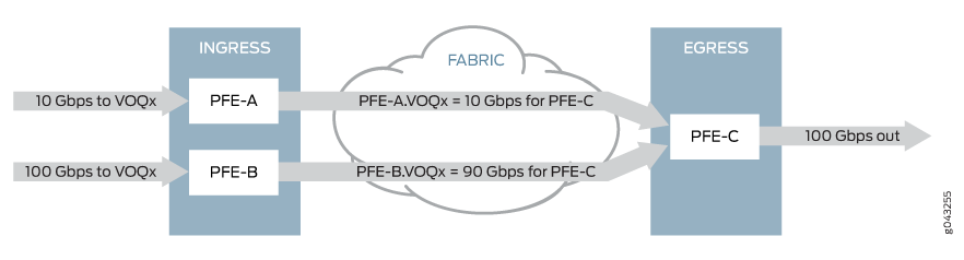
In Figure 6, we have a total of 110 Gbps of source data destined for a 100 Gbps output interface. As a result, we need to drop 10 Gbps of data. Where does the drop occur and how does this drop affect traffic from PFE-A versus PFE-B?
Because PFE-A and PFE-B are serviced in round-robin fashion by egress PFE-C, all 10 Gbps of traffic from PFE-A makes it through to the egress output port. However, 10 Gbps of data is dropped on PFE-B, allowing only 90 Gbps of data from PFE-B to be sent to PFE-C. So, the 10 Gbps stream has a 0% drop and the 100 Gbps stream has only a 10% drop.
However, if PFE-A and PFE-B were each sourcing 100 Gbps of data, then they would each drop 50 Gbps of data. This is because the egress PFE-C actually controls the servicing and drain rate on the ingress virtual queues using the round-robin algorithm. With the round-robin algorithm, higher bandwidth sources are always penalized when multiple sources are present. The algorithm attempts to make the two sources equal in bandwidth; however, because it cannot raise the bandwidth of the slower source, it drops the bandwidth of the higher source. The round robin algorithm continues this sequence until the sources have equal egress bandwidth.
Each ingress Packet Forwarding Engine provides up to eight VOQs for a single egress port. The egress Packet Forwarding Engine distributes the bandwidth to each ingress VOQ; therefore the VOQs receive equal treatment regardless of their presented load. The drain-rate of a queue is the rate at which a queue is draining. The egress Packet Forwarding Engine divides its bandwidth for each output queue equally across the ingress Packet Forwarding Engines. So, the drain-rate of each ingress Packet Forwarding Engine=Drain-rate of output queue/Number of ingress Packet Forwarding Engines.
Handling Congestion
There are two main types of congestion that can occur:
-
Ingress congestion — Occurs when the ingress Packet Forwarding Engine has more offered load than the egress can handle. The ingress congestion case is very similarly to a traditional router in that the queues build-up and once the queues cross their configured threshold, packets are dropped.
-
Egress congestion — Occurs when the sum of all the ingress Packet Forwarding Engines exceeds the capability of the egress router. All drops are performed on the ingress Packet Forwarding Engines. However, the size of the ingress queue is attenuated by the queue’s drain-rate (how fast the egress Packet Forwarding Engine is requesting packets). This rate is essentially determined by the rate that requests are being converted in to grants by the egress Packet Forwarding Engine. The egress Packet Forwarding Engine services the request-to-grant conversion in round-robin fashion; it is not dependent on the ingress Packet Forwarding Engines offered load. For instance, if the ingress Packet Forwarding Engine’s drain-rate is half of what it expects it to be (as is the case when 2 ingress Packet Forwarding Engines are presenting an oversubscribed load for the target output queue), then the ingress Packet Forwarding Engine’s reduce the size of this queue to be half of its original size (when it was getting its full drain rate).
VOQ Queue-depth Monitoring
VOQ queue-depth monitoring, or latency monitoring, measures peak queue occupancy of a VOQ. This feature enables the reporting of peak queue length for a given physical interface for each individual Packet Forwarding Engine.
In addition to the peak queue-length data, each queue also maintains drop statistics and time-averaged queue length on the ingress data path. Also, each queue maintains queue transmission statistics on the egress data path.
In a typical deployment scenario that uses strict-priority scheduling, a
HIGH priority queue can starve LOW priority
queues. Thus the packets in such LOW priority queues can remain
longer than desired. You can use this VOQ queue-depth monitoring feature, along with
queue transmission statistics, to detect such stalled conditions.
You can only enable VOQ queue-depth monitoring on transit WAN interfaces.
To enable VOQ queue-depth monitoring on an interface, you first create a monitoring
profile, and then attach that profile to the interface. If you attach a monitoring
profile to an aggregated Ethernet (ae-) interface, each member interface has its own
dedicated hardware VOQ monitor, unless you also apply the shared
option to the monitoring profile attached to the ae- interface.
The monitoring profile reports virtual output queue (VOQ) depth individually on each
interface. However, given finite number of hardware monitoring profile IDs on a
system, this process can quickly consume the maximum supported hardware monitoring
profile IDs on large systems. By default, a monitoring profile that you assign to an
ae- interface replicates across all members of the ae- interface. Therefore, to
conserve monitoring profile IDs, include the shared option at the
[set class-of-service interfaces ae-interface
                    monitoring-profile
                    profile-name]
hierarchy level. The configured
shared option creates only one monitoring profile ID to share
across all member interfaces. The option also reports the largest peak on a member
interface as the common peak for the ae- interface.
You cannot enable the shared option on mixed mode ae-
interfaces.
Each monitoring profile consists of one or more export filters. An export filter defines a peak queue-length percentage threshold for one or more queues on the physical interface. Once the defined peak queue-length percentage threshold is met for any queue in the export filter, Junos exports the VOQ telemetry data for all queues in the export filter.
The queue-depth monitoring data goes out only through a telemetry channel. In addition to configuring a monitoring profile (as shown below) you must initiate a regular sensor subscription in order for the data to go out. There is no CLI display option.
Configure VOQ Queue-depth Monitoring
Configure VOQ queue-depth monitoring to export queue utilization data. You can use this data to monitor micro-bursts and also assist in identifying stalled transit output queues. To configure VOQ queue-depth monitoring:
- Configure the monitoring profile.
- Attach the monitoring profile to an interface.
To configure the monitoring profile:
- Name the monitoring profile. For
example:
[edit class-of-service]
set monitoring-profile mp1
- Name an export filter for the montoring profile. For
example:
[edit class-of-service monitoring-profile mp1]
set export-filters ef1
- Define which queues (0 through 7) belong to the export filter. For
example:
[edit class-of-service monitoring-profile mp1 export-filters ef1]
set queue [0 1]
- (Optional) Define the threshold peak queue length percentage to export VOQ
telemetry data. The default percentage is 0. For
example:
[edit class-of-service monitoring-profile mp1 export-filters ef1]
set peak-queue-length percent 50
- (Optional) Define one or more other export filters for the monitoring
profile. For
example:
[edit class-of-service monitoring-profile mp1]
set export-filters ef2 queue [2 3]
- Commit your changes.
To attach the monitoring profile to an interface:
- Attach the monitoring profile to an interface. For
example:
[edit class-of-service]
set interfaces et-0/0/1 monitoring-profile mp1
set interfaces ae0 monitoring-profile mp1 shared
- Commit your changes.
Check your configuration. For example:
[edit class-of-service]
user@host# show
monitoring-profile mp1 {
    export-filters ef1 {
        peak-queue-length {
            percent 50;
        }
        queue [ 0 1 ];
    }
    export-filters ef2 {
        queue [ 2 3 ];
    }
}
interfaces {

    ae0 {
        monitoring-profile mp1 shared;
    }
    et-0/0/1 {
        monitoring-profile mp1;
    }
}
Run these show commands to verify your configuration:
user@host> show class-of-service interface et-0/0/1
Physical interface: et-0/0/1, Index: 1098
Maximum usable queues: 8, Queues in use: 4
Exclude aggregate overhead bytes: disabled
Logical interface aggregate statistics: disabled
  Scheduler map: default, Index: 0
  Congestion-notification: Disabled
  Monitoring Profile Name: mp1

  Logical interface: et-0/0/1.16386, Index: 1057

user@host> show class-of-service interface ae0
Physical interface: ae0, Index: 7860
Maximum usable queues: 8, Queues in use: 4
Exclude aggregate overhead bytes: disabled
Logical interface aggregate statistics: disabled
  Scheduler map: default, Index: 0
  Congestion-notification: Disabled
  Monitoring Profile Name: mp1 [shared]


user@host> show class-of-service monitoring-profile
Monitoring profile: mp1
  Export filter         Queue Number                    Peak Queue Length
  ef1                    0                                 50%
  ef1                    1                                 50%
  ef2                    2                                 0%
  ef2                    3                                 0%
As you can see from this example, not setting a peak-queue-length
percent for an export filter defaults the percentage to 0
percent, as export filter ef2 shows. This example shows
different queues on the physical interface having different peak queue
length thresholds for exporting VOQ telemetry data.