Packet Flow Through the Junos CoS Process
Perhaps the best way to understand Junos CoS is to examine how a packet is treated on its way through the CoS process. This topic includes a description of each step and figures illustrating the process.
The following steps describe the CoS process:
A logical interface has one or more classifiers of different types applied to it (at the
[edit class-of-service interfaces]hierarchy level). The types of classifiers are based on which part of the incoming packet the classifier examines (for example, EXP bits, IEEE 802.1p bits, or DSCP bits). You can use a translation table to rewrite the values of these bits on ingress.The classifier assigns the packet to a forwarding class and a loss priority (at the
[edit class-of-service classifiers]hierarchy level).Each forwarding class is assigned to a queue (at the
[edit class-of-service forwarding-classes]hierarchy level).Input (and output) policers meter traffic and might change the forwarding class and loss priority if a traffic flow exceeds its service level.
The physical or logical interface has a scheduler map applied to it (at the
[edit class-of-service interfaces]hierarchy level).At the
[edit class-of-service interfaces]hierarchy level, thescheduler-mapandrewrite-rulesstatements affect the outgoing packets, and theclassifiersstatement affects the incoming packets.The scheduler defines how traffic is treated in the output queue—for example, the transmit rate, buffer size, priority, and drop profile (at the
[edit class-of-service schedulers]hierarchy level).The scheduler map assigns a scheduler to each forwarding class (at the
[edit class-of-service scheduler-maps]hierarchy level).The drop-profile defines how aggressively to drop packets that are using a particular scheduler (at the
[edit class-of-service
drop-profiles]
hierarchy level).The rewrite rule takes effect as the packet leaves a logical interface that has a rewrite rule configured (at the
[edit class-of-service
rewrite-rules]
hierarchy level). The rewrite rule writes information to the packet (for example, EXP or DSCP bits) according to the forwarding class and loss priority of the packet.
Figure 1 and Figure 2 show the components of the Junos CoS features, illustrating the sequence in which they interact.
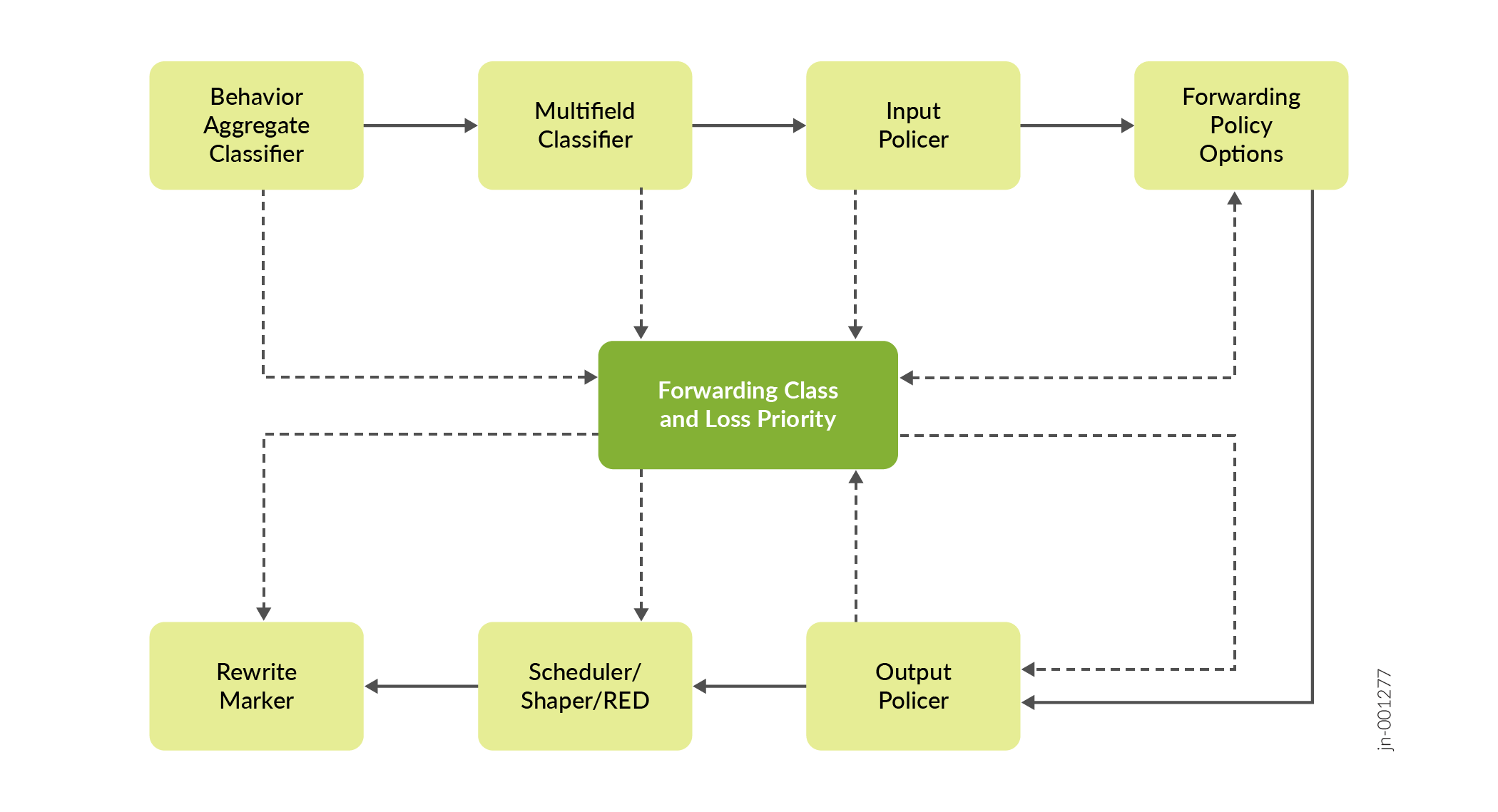
Each outer box in Figure 2 represents a process component. The components in the upper row apply to inbound packets, and the components in the lower row apply to outbound packets. The arrows with the solid lines point in the direction of packet flow.
The middle box (forwarding class and loss priority) represents two data values that can either be inputs to or outputs of the process components. The arrows with the dotted lines indicate inputs and outputs (or settings and actions based on settings). For example, the multifield classifier sets the forwarding class and loss priority of incoming packets. This means that the forwarding class and loss priority are outputs of the classifier; thus, the arrow points away from the classifier. The scheduler receives the forwarding class and loss priority settings, and queues the outgoing packet based on those settings. This means that the forwarding class and loss priority are inputs to the scheduler; thus, the arrow points to the scheduler.
Typically, only a combination of some components (not all) is used to define a CoS service offering.
Packet Flow Within Routers Overview
Although the architecture of Juniper Networks devices differ in detail, the overall flow of a packet within each device remains consistent.
When a packet enters a Juniper Networks device, the PIC or other interface type receiving the packet retrieves it from the network and verifies that the link-layer information is valid. The packet is then passed to the concentrator device such as a Flexible PIC Concentrator (FPC), where the data link and network layer information is verified. In addition, the FPC is responsible for segmenting the packet into 64-byte units called J-cells. These cells are then written into packet storage memory while a notification cell is sent to the route lookup engine. The destination address listed in the notification cell is located in the forwarding table, and the next hop of the packet is written into the result cell. This result cell is queued on the appropriate outbound FPC until the outgoing interface is ready to transmit the packet. The FPC then reads the J-cells out of memory, re-forms the original packet, and sends the packet to the outgoing PIC, where it is transmitted back into the network.