CoS Three-Level Hierarchical Scheduling on MPLS Pseudowire Subscriber Interfaces
In three-level hierarchical scheduling, the CoS scheduler nodes at level 1, level 2, and level 3 form a scheduling hierarchy. You can configure many different three-level scheduling hierarchies, depending on the location of the interface set and the use of underlying interfaces. In all variations, the physical interface on which the logical tunnel resides is a level 1 CoS scheduler node and the queues reside at level 4. Three-level scheduling hierarchies can have up to eight class of service queues. Table 1summarizes the most common three-level hierarchical scheduling configurations and shows the interface hierarchy and CoS scheduler nodes.
|
Level 1 |
Level 2 |
Level 3 |
Level 4 |
|---|---|---|---|
|
Physical interface |
Pseudowire interface set |
Pseudowire service logical interfaces |
One or more queues |
|
Physical interface |
Pseudowire transport logical interface |
Pseudowire interface set |
One or more queues |
|
Physical interface |
Pseudowire transport logical interface |
Pseudowire service logical interfaces |
One or more queues |
Three-Level Scheduling Hierarchy: Pseudowire Logical Interfaces over a Transport Logical Interface
Figure 1 shows an MPLS pseudowire three-level scheduling hierarchy that includes two pseudowire service logical interfaces over a pseudowire transport logical interface. This variation uses the following scheduler nodes:
-
Level 4—Forwarding class-based queues
-
Level 3—Pseudowire service logical interfaces (ps0.1 and ps0.2) for subscriber sessions
-
Level 2—Pseudowire transport logical interface (ps0.0)
-
Level 1—Common/shared physical interface of the logical tunnel anchor point
You apply the traffic-control profiles at the pseudowire transport logical interfaces (level 2) and the pseudowire service logical interfaces (level 3).
Three-Level Scheduling Hierarchy : Pseudowire Service Logical Interfaces over a Pseudowire Service Interface Set
Figure 2 shows another variation of MPLS pseudowire three-level hierarchical scheduling that includes two pseudowire service logical interfaces over a pseudowire service interface set. This variation uses the following CoS scheduler nodes:
-
Level 4—Forwarding class-based queues
-
Level 3—Pseudowire service logical interfaces (ps0.1 and ps0.2)
-
Level 2—Pseudowire service interface set
-
Level 1—Common/shared physical interface of the logical tunnel anchor point
You apply the traffic-control profile at the pseudowire service interfaces (level 3) and at the interface set (level 2). This variation is most useful for subscriber edge deployments.
Three-Level Scheduling Hierarchy Combined Deployment Scenario
Figure 3 shows a deployment scenario that combines the three-level hierarchical scheduling scenarios in Figure 1 and Figure 2.
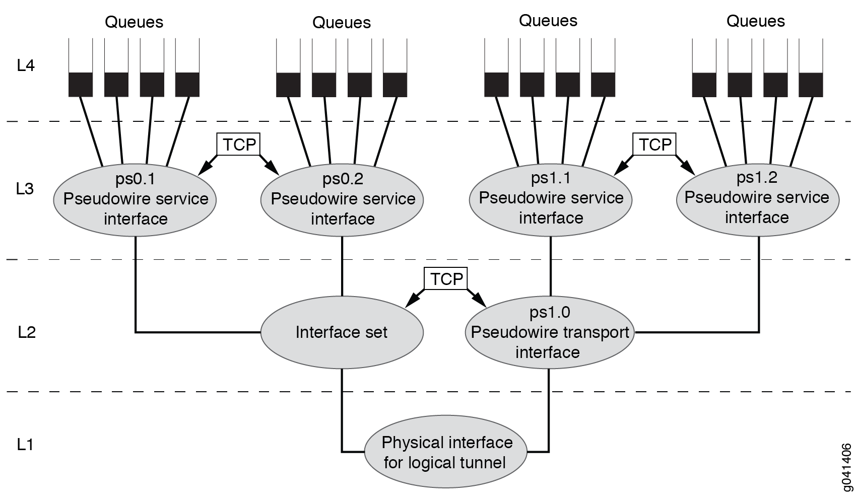
This variation uses the following CoS scheduler nodes:
-
Level 4—Forwarding class-based queues
-
Level 3—Pseudowire service logical interfaces (ps0.1, ps0.2, ps1.1, and ps1.2)
-
Level 2—Service interface set for pseudowire service interfaces (ps0.1 and ps0.2) and transport logical interface (ps1.0) for the pseudowire service logical interfaces (ps1.1 and ps1.2)
-
Level 1—Common/shared physical interface of the logical tunnel anchor point
You apply the traffic-control profiles to the interfaces at both level 2 and level 3, as well as the interface set at level 2.