Chassis Cluster Support on SRX100, SRX210, SRX220, SRX240, SRX550M, SRX650, SRX1400, SRX3400, and SRX3600 Devices
This topic includes the supported information for SRX100, SRX210, SRX220, SRX240, SRX550M, SRX650, SRX1400, SRX3400, and SRX3600 devices.
SRX Series Chassis Cluster Configuration Overview
Following are the prerequisites for configuring a chassis cluster:
Flow and Processing
Flowd monitoring is supported on SRX100, SRX210, SRX 220, SRX240, SRX550M, and SRX650 devices.
Monitoring
The maximum number of monitoring IPs that can be configured per cluster is 64 for SRX550M devices. On SRX550M devices, logs cannot be sent to NSM when logging is configured in the stream mode.
Installation and Upgrade
For SRX550M devices, the reboot parameter is not available, because
the devices in a cluster are automatically rebooted following an in-band cluster
upgrade (ICU).
ICU is available with the no-sync option only for SRX550M devices.
For SRX550M devices, the devices in a chassis cluster can be upgraded with a minimal service disruption of approximately 30 seconds using ICU with the no-sync option.
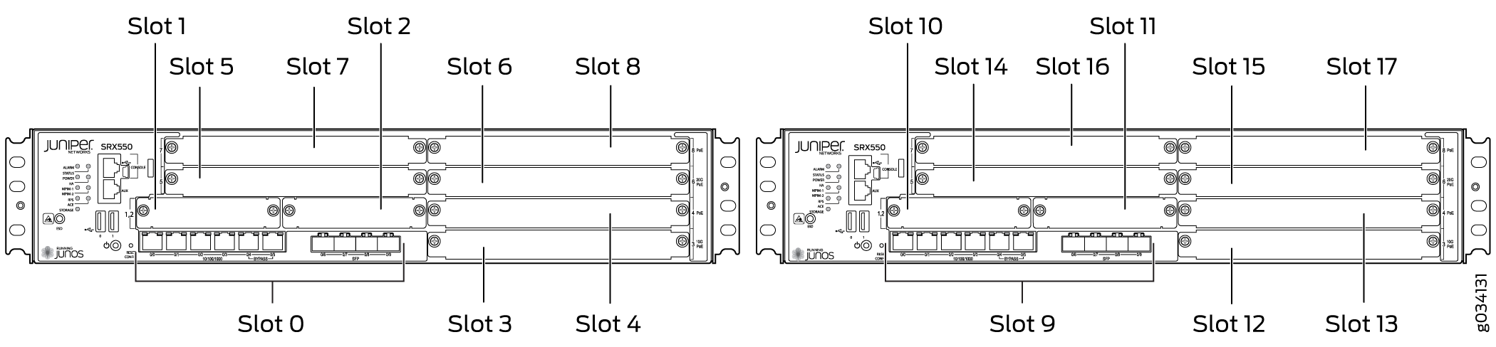
Chassis Cluster Slot Numbering and Physical Port and Logical Interface Naming for SRX100, SRX210, SRX220, SRX240, SRX550M, and SRX650.
Following are the prerequisites for configuring a chassis cluster:
-
On SRX550M any existing configurations associated with interfaces that transform to the fxp0 management port and the control port should be removed.
-
For SRX550M chassis clusters, the placement and type of GPIMs, XGPIMs, XPIMs, and Mini-PIMs (as applicable) must match in the two devices.
For SRX550M devices, control interfaces are dedicated Gigabit Ethernet ports.
Information about chassis cluster slot numbering is also provided in Figure 1, Figure 2, Figure 3, Figure 4, and Figure 5.
Layer 2 switching must not be enabled on an SRX Series Firewall when chassis clustering is enabled. If you have enabled Layer 2 switching, make sure you disable it before enabling chassis clustering.
The factory default configuration for SRX100, SRX210, and SRX220 devices automatically enables Layer 2 Ethernet switching. Because Layer 2 Ethernet switching is not supported in chassis cluster mode, if you use the factory default configuration for these devices, you must delete the Ethernet switching configuration before you enable chassis clustering. See Disabling Switching on SRX100, SRX210, and SRX220 Devices Before Enabling Chassis Clustering.
In chassis cluster mode, the interfaces on the secondary node are renumbered internally. For example, the management interface port on the front panel of each SRX210 device is still labeled fe-0/0/6, but internally, the node 1 port is referred to as fe-2/0/6.
For SRX650 devices, control interfaces are dedicated Gigabit Ethernet ports.
For SRX100, SRX220, and SRX210 devices, after you enable chassis clustering and reboot the system, the built-in interface named fe-0/0/6 is repurposed as the management interface and is automatically renamed fxp0.
For SRX550 devices, control interfaces are dedicated Gigabit Ethernet ports.
For SRX210 devices, after you enable chassis clustering and reboot the system, the built-in interface named fe-0/0/7 is repurposed as the control interface and is automatically renamed fxp1.
In chassis cluster mode, the interfaces on the secondary node are renumbered internally. For example, the management interface port on the front panel of each SRX210 device is still labeled fe-0/0/6, but internally, the node 1 port is referred to as fe-2/0/6.
For SRX240 devices, control interfaces are dedicated Gigabit
Ethernet ports. For SRX100 and SRX220 devices, after you enable chassis
clustering and reboot the system, the built-in interface named fe-0/0/7 is repurposed as the control interface and is automatically
renamed fxp1.
For SRX210 Services Gateways, the base and enhanced versions of a model can be used to form a cluster. For example:
SRX210B and SRX210BE
SRX210H and SRX210HE
However, the following combinations cannot be used to form a cluster:
SRX210B and SRX210H
SRX210B and SRX210HE
SRX210BE and SRX210H
SRX210BE and SRX210HE
Figure 6, Figure 7, Figure 8, Figure 9, Figure 10, Figure 11 and all show pairs of SRX Series Firewalls with the fabric links and control links connected.
The fabric link connection for the SRX100 and SRX210 must be a pair of either Fast Ethernet or Gigabit Ethernet interfaces. The fabric link connection must be any pair of either Gigabit Ethernet or 10-Gigabit Ethernet interfaces on all SRX Series Firewalls.
For some SRX Series Firewalls, such as the SRX100 and SRX200 line devices, do not have a dedicated port for fxp0. For SRX100, SRX210, the fxp0 interface is repurposed from a built-in interface.
|
SRX Series Services Gateway |
Renumbering Constant |
Node 0 Interface Name |
Node 1 Interface Name |
|---|---|---|---|
|
SRX550M |
9 |
ge-0/0/0 |
ge-9/0/0 |
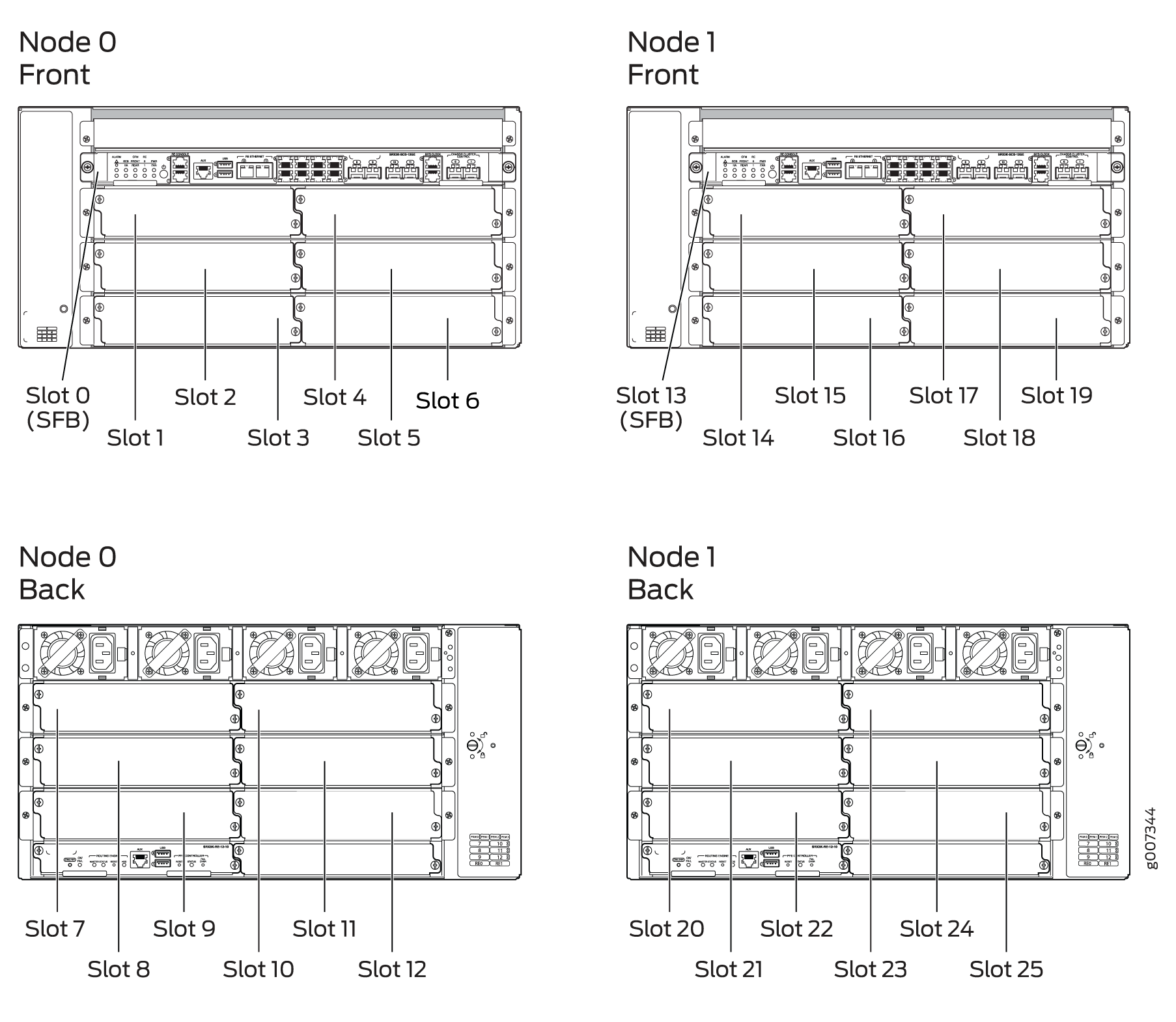
Chassis Cluster Slot Numbering and Physical Port and Logical Interface Naming for SRX3600, SRX3400, and SRX1400
Table 2 shows the slot numbering, as well as the physical port and logical interface numbering, for both of the SRX Series Firewalls that become node 0 and node 1 of the chassis cluster after the cluster is formed.
Model |
Chassis |
Maximum Slots Per Node |
Slot Numbering in a Cluster |
Management Physical Port/Logical Interface |
Control Physical Port/Logical Interface |
Fabric Physical Port/Logical Interface |
|---|---|---|---|---|---|---|
|
SRX550M |
Node 0 |
9 (PIM slots) |
0-8 |
ge-0/0/0 |
ge-0/0/1 |
Any Ethernet port |
|
fxp0 |
fxp1 |
fab0 |
||||
|
Node 1 |
9—17 |
ge-9/0/0 |
ge-9/0/1 |
Any Ethernet port |
||
|
fxp0 |
fxp1 |
fab1 |
||||
SRX3600 |
Node 0 |
13 (CFM slots) |
0 — 12 |
Dedicated Gigabit Ethernet port |
Dedicated Gigabit Ethernet port |
Any Ethernet port |
fxp0 |
em0 |
fab0 |
||||
Node 1 |
13 — 25 |
Dedicated Gigabit Ethernet port |
Dedicated Gigabit Ethernet port |
Any Ethernet port |
||
fxp0 |
em0 |
fab1 |
||||
SRX3400 |
Node 0 |
8 (CFM slots) |
0 — 7 |
Dedicated Gigabit Ethernet port |
Dedicated Gigabit Ethernet port |
Any Ethernet port |
fxp0 |
em0 |
fab0 |
||||
Node 1 |
8 — 15 |
Dedicated Gigabit Ethernet port |
Dedicated Gigabit Ethernet port |
Any Ethernet port |
||
fxp0 |
em0 |
fab1 |
||||
SRX1400 |
Node 0 |
4 (FPC slots) |
0 — 3 |
Dedicated Gigabit Ethernet port |
Dedicated Gigabit Ethernet port |
Any Ethernet port |
fxp0 |
em0 |
fab0 |
||||
Node 1 |
4 — 7 |
Dedicated Gigabit Ethernet port |
Dedicated Gigabit Ethernet port |
Any Ethernet port |
||
fxp0 |
em0 |
fab1 |
Information about chassis cluster slot numbering is also provided in Figure 12, Figure 13, Figure 15, and Figure 14.
In a large chassis cluster configuration on an SRX3400 or SRX3600 device, the heartbeat timers are recommended to increase the wait time to 8 seconds.
For SRX550M devices, connect the ge-0/0/1 on node 0 to the ge-9/0/1 on node 1.
You can connect two control links (SRX1400 and SRX3000 lines only) and two fabric links between the two devices in the cluster to reduce the chance of control link and fabric link failure. See Understanding Chassis Cluster Dual Control Links and Understanding Chassis Cluster Dual Fabric Links.
Figure 19 show pairs of SRX Series Firewalls with the fabric links and control links connected.
Figure 17 and Figure 18 show pairs of SRX Series Firewalls with the fabric links and control links connected.

For dual control links on SRX3000 line devices, the Routing Engine must be in slot 0 and the SRX Clustering Module (SCM) in slot 1. The opposite configuration (SCM in slot 0 and Routing Engine in slot 1) is not supported.
Supported Fabric Interface Types for SRX Series Firewalls (SRX210, SRX240, SRX220, SRX100, and SRX650 Devices)
For SRX210 devices, the fabric link can be any pair of Gigabit Ethernet interfaces or Fast Ethernet interfaces (as applicable). Interfaces on SRX210 devices are Fast Ethernet or Gigabit Ethernet (the paired interfaces must be of a similar type) and all interfaces on SRX100 devices are Fast Ethernet interfaces.
For SRX550 devices, the fabric link can be any pair of Gigabit Ethernet interfaces or Fast Ethernet interfaces (as applicable).
For SRX Series chassis clusters made up of SRX550M devices, SFP interfaces on Mini-PIMs cannot be used as the fabric link.
For SRX550M devices, the total number of logical interfaces that you can configure across all the redundant Ethernet (reth) interfaces in a chassis cluster deployment is 1024.
For SRX Series chassis clusters, the fabric link can be any pair of Ethernet interfaces spanning the cluster; the fabric link can be any pair of Gigabit Ethernet interface.
Table 3 shows the fabric interface types that are supported for SRX Series Firewalls.
SRX550 |
SRX650 |
SRX240 |
SRX220 |
SRX100 |
SRX210 |
|---|---|---|---|---|---|
Fast Ethernet |
Fast Ethernet |
Fast Ethernet |
Fast Ethernet |
Fast Ethernet |
|
Gigabit Ethernet |
Gigabit Ethernet |
Gigabit Ethernet |
Gigabit Ethernet |
Gigabit Ethernet |
Redundant Ethernet Interfaces
Device |
Maximum Number of reth Interfaces |
|---|---|
SRX100 |
8 |
SRX210 |
8 |
SRX220 |
8 |
SRX240 |
24 |
|
SRX550M |
58 |
SRX650 |
68 |
Point-to-Point Protocol over Ethernet (PPPoE) over redundant Ethernet (reth) interface is supported on SRX100, SRX210, SRX220, SRX240, SRX550M, and SRX650 devices in chassis cluster mode. This feature allows an existing PPPoE session to continue without starting a new PPP0E session in the event of a failover.
-
On SRX550M devices, the number of child interfaces is restricted to 16 on the reth interface (eight per node).
For SRX100, SRX220, and SRX240 devices, the total number of logical interfaces that you can configure across all the redundant Ethernet (reth) interfaces in a chassis cluster deployment is 1024.
On SRX550M devices, the speed mode and link mode configuration is available for member interfaces of a reth interface.
IP address monitoring cannot be used on a chassis cluster running in transparent mode. The maximum number of monitoring IP addresses that can be configured per cluster is 32 for the SRX1400 device and the SRX3000 line of devices.
Control Links
For SRX100, SRX210, and SRX220 devices, the control link uses the fe-0/0/7 interface.
For SRX210 devices, the total number of logical interfaces that you can configure across all the redundant Ethernet (reth) interfaces in a chassis cluster deployment is 1024.
For SRX240, SRX650M, devices, the control link uses the
ge-0/0/1interface.
|
Device |
Management (fxp0) |
HA Control (fxp1) |
Fabric (fab0 and fab1)—must be configured |
|---|---|---|---|
|
SRX550M |
ge-0/0/0 |
ge-0/0/1 |
Any ge or xe interface |
|
Command |
SRX100 |
SRX210 |
SRX220 |
SRX240 |
SRX550M |
|---|---|---|---|---|---|
|
set interfaces fab0 fabric-options member-interfaces |
|
|
|
|
|
|
set interfaces fab1 fabric-options member-interfaces |
|
|
|
|
|
|
set chassis cluster redundancy-group 1 interface-monitor |
|
|
|
|
|
|
set chassis cluster redundancy-group 1 interface-monitor |
|
|
|
|
|
|
set chassis cluster redundancy-group 1 interface-monitor |
|
|
|
|
|
|
set chassis cluster redundancy-group 1 interface-monitor |
|
|
|
|
|
|
|
|
|
|
|
|
|
|
|
|
|
|
|
|
|
|
|
|
|
|
|
|
|
|
|
|
|
ISSU System Requirements for SRX1400, SRX3400 and SRX3600
To perform an ISSU, your device must be running a Junos OS release that supports ISSU for the specific platform. See Table 7 for platform support.
Device |
Junos OS Release |
|---|---|
SRX1400 |
12.1X47-D10 |
SRX3400 |
12.1X47-D10 |
SRX3600 |
12.1X47-D10 |
Example: Configure IRB and VLAN with Members Across Two Nodes on a Security Device using Tagged
Our content testing team has validated and updated this example.
Requirements
This example uses the following hardware and software components:
-
configure a switching fabric interface on both nodes to configure Ethernet switching-related features on the nodes. See Example: Configuring Switch Fabric Interfaces to Enable Switching in Chassis Cluster Mode on a Security Device
-
SRX550 security device
-
interface-modeis supported in 15.1X49 release. -
port-modeis supported in 12.1 and 12.3X48 releases.
Overview
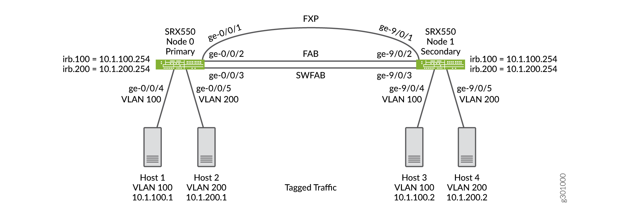
This example shows the configuration of a VLAN with members across node 0 and node 1.
Topology
Figure 20 shows the Layer 2 Ethernet switching across chassis cluster nodes using tagged traffic.
Configuration
Procedure
CLI Quick Configuration
To quickly configure this section of the example, copy the following
commands, paste them into a text file, remove any line breaks, change
any details necessary to match your network configuration, copy and
paste the commands into the CLI at the [edit] hierarchy
level, and then enter commit from configuration
mode.
set security zones security-zone trust host-inbound-traffic system-services all
set security zones security-zone trust interfaces irb.100
set security zones security-zone trust interfaces irb.200
set interfaces ge-0/0/4 unit 0 family ethernet-switching interface-mode trunk
set interfaces ge-0/0/4 unit 0 family ethernet-switching vlan members v100
set interfaces ge-0/0/5 unit 0 family ethernet-switching interface-mode trunk
set interfaces ge-0/0/5 unit 0 family ethernet-switching vlan members v200
set interfaces ge-9/0/4 unit 0 family ethernet-switching interface-mode trunk
set interfaces ge-9/0/4 unit 0 family ethernet-switching vlan members v100
set interfaces ge-9/0/5 unit 0 family ethernet-switching interface-mode trunk
set interfaces ge-9/0/5 unit 0 family ethernet-switching vlan members v200
set interfaces fab0 fabric-options member-interfaces ge-0/0/2
set interfaces fab1 fabric-options member-interfaces ge-9/0/2
set interfaces irb unit 100 family inet address 10.1.100.254/24
set interfaces irb unit 200 family inet address 10.1.200.254/24
set interfaces swfab0 fabric-options member-interfaces ge-0/0/3
set interfaces swfab1 fabric-options member-interfaces ge-9/0/3
set vlans v100 vlan-id 100
set vlans v100 l3-interface irb.100
set vlans v200 vlan-id 200
set vlans v200 l3-interface irb.200
Step-by-Step Procedure
To configure IRB and a VLAN:
-
Configure security zones.
{primary:node0} [edit security zones] user@host# set security-zone trust host-inbound-traffic system-services all user@host# set security-zone trust interfaces irb.100 user@host# set security-zone trust interfaces irb.200 -
Configure Ethernet switching on the node0 interfaces.
{primary:node0} [edit interfaces] user@host# set ge-0/0/4 unit 0 family ethernet-switching interface-mode trunk user@host# set ge-0/0/4 unit 0 family ethernet-switching vlan members v100 user@host# set ge-0/0/5 unit 0 family ethernet-switching interface-mode trunk user@host# set ge-0/0/5 unit 0 family ethernet-switching vlan members v200 user@host# set ge-9/0/4 unit 0 family ethernet-switching interface-mode trunk user@host# set ge-9/0/4 unit 0 family ethernet-switching vlan members v100 user@host# set ge-9/0/5 unit 0 family ethernet-switching interface-mode trunk user@host# set ge-9/0/5 unit 0 family ethernet-switching vlan members v200 -
Define the interfaces used for the fab connection (data plane links for RTOsync) by using physical ports from each node. These interfaces must be connected back-to-back, or through a Layer 2 infrastructure.
{primary:node0} [edit interfaces] user@host# set fab0 fabric-options member-interfaces ge-0/0/2 user@host# set fab1 fabric-options member-interfaces ge-9/0/2 -
configure a switching fabric interface on both nodes to configure Ethernet switching-related features on the nodes.
{primary:node0} [edit interfaces] user@host# set swfab0 fabric-options member-interfaces ge-0/0/3 user@host# set swfab1 fabric-options member-interfaces ge-9/0/3 -
Configure the irb interface.
{primary:node0} [edit interfaces] user@host# set irb unit 100 family inet address 10.1.100.254/24 user@host# set irb unit 200 family inet address 10.1.200.254/24 -
Create and associate a VLAN interface with the VLAN.
{primary:node0} [edit vlans] user@host# set v100 vlan-id 100 user@host# set v100 l3-interface irb.100 user@host# set v200 vlan-id 200 user@host# set v200 l3-interface irb.200 -
If you are done configuring the device, commit the configuration.
[edit]
user@host# commit
Results
From configuration mode, confirm your configuration by entering the
show security, show interfaces,
and show vlans commands. If the output does not display
the intended configuration, repeat the configuration instructions in
this example to correct the configuration.
[edit]
user@host# show security
zones {
    security-zone trust {
        host-inbound-traffic {
            system-services {
                all;
            }
        }
        interfaces {
            irb.100;
            irb.200;
        }
    }
}
[edit]
user@host# show interfaces
ge-0/0/4 {
    unit 0 {
        family ethernet-switching {
            interface-mode trunk;
            vlan {
                members v100;
            }
        }
    }
}
ge-0/0/5 {
    unit 0 {
        family ethernet-switching {
            interface-mode trunk;
            vlan {
                members v200;
            }
        }
    }
}
ge-9/0/4 {
    unit 0 {
        family ethernet-switching {
            interface-mode trunk;
            vlan {
                members v100;
            }
        }
    }
}
ge-9/0/5 {
    unit 0 {
        family ethernet-switching {
            interface-mode trunk;
            vlan {
                members v200;
            }
        }
    }
}
fab0 {
    fabric-options {
        member-interfaces {
            ge-0/0/2;
        }
    }
}
fab1 {
    fabric-options {
        member-interfaces {
            ge-9/0/2;
        }
    }
}
irb {
    unit 100 {
        family inet {
            address 10.1.100.254/24;
        }
    }
    unit 200 {
        family inet {
            address 10.1.200.254/24;
        }
    }
}
swfab0 {
    fabric-options {
        member-interfaces {
            ge-0/0/3;
        }
    }
}
swfab1 {
    fabric-options {
        member-interfaces {
            ge-9/0/3;
        }
    }
}
[edit]
user@host# show vlans
v100 {
    vlan-id 100;
    l3-interface irb.100;
}
v200 {
    vlan-id 200;
    l3-interface irb.200;
}
Verification
Verifying Tagged VLAN With IRB
Purpose
Verify that the configuration for tagged VLAN with IRB is working properly.
Action
From operational mode, enter the show chassis cluster
interfaces command.
user@host> show chassis cluster interfaces
Control link status: Up

Control interfaces:
    Index   Interface   Monitored-Status   Internal-SA   Security
    0       fxp1        Up                 Disabled      Disabled

Fabric link status: Up

Fabric interfaces:
    Name    Child-interface    Status                    Security
                               (Physical/Monitored)
    fab0    ge-0/0/2           Up   / Up                 Enabled
    fab0
    fab1    ge-9/0/2           Up   / Up                 Enabled
    fab1

Redundant-pseudo-interface Information:
    Name         Status      Redundancy-group
    lo0          Up          0
From operational mode, enter the show ethernet-switching
table command.
user@host> show ethernet-switching table
MAC flags (S - static MAC, D - dynamic MAC, L - locally learned, P - Persistent static, C - Control MAC
           SE - statistics enabled, NM - non configured MAC, R - remote PE MAC, O - ovsdb MAC)


Ethernet switching table : 4 entries, 4 learned
Routing instance : default-switch
    Vlan                MAC                 MAC         Age    Logical                NH        RTR
    name                address             flags              interface              Index     ID
    v100                08:81:f4:8a:eb:52   D             -   ge-9/0/4.0             0         0
    v100                08:81:f4:8a:eb:54   D             -   ge-0/0/4.0             0         0
    v200                08:81:f4:8a:eb:53   D             -   ge-9/0/5.0             0         0
    v200                08:81:f4:8a:eb:55   D             -   ge-0/0/5.0             0         0
From operational mode, enter the show arp
command.
user@host> show arp
MAC Address       Address         Name                      Interface               Flags
08:81:f4:8a:eb:54 10.1.100.1      10.1.100.1                irb.100                 none
08:81:f4:8a:eb:52 10.1.100.2      10.1.100.2                irb.100                 none
08:81:f4:8a:eb:55 10.1.200.1      10.1.200.1                irb.200                 none
08:81:f4:8a:eb:53 10.1.200.2      10.1.200.2                irb.200                 none
ec:3e:f7:c6:81:b0 30.17.0.2       30.17.0.2                 fab0.0                  permanent
f0:4b:3a:09:cb:30 30.18.0.1       30.18.0.1                 fab1.0                  permanent
ec:3e:f7:c6:80:81 130.16.0.1      130.16.0.1                fxp1.0                  none
Total entries: 7
From operational mode, enter the show ethernet-switching
interface command to view the information about
Ethernet switching interfaces.
user@host> show ethernet-switching interface
Routing Instance Name : default-switch
Logical Interface flags (DL - disable learning, AD - packet action drop,
                         LH - MAC limit hit, DN - interface down,
                         MMAS - Mac-move action shutdown,  AS - Autostate-exclude enabled,
                         SCTL - shutdown by Storm-control, MI - MAC+IP limit hit)

Logical         Vlan                   TAG   MAC    MAC+IP STP         Logical          Tagging
interface       members                      limit  limit  state       interface flags
ge-0/0/5.0                                   16383  8192                                tagged
                v200                   200   1024   1024   Forwarding                   tagged
Routing Instance Name : default-switch
Logical Interface flags (DL - disable learning, AD - packet action drop,
                         LH - MAC limit hit, DN - interface down,
                         MMAS - Mac-move action shutdown,  AS - Autostate-exclude enabled,
                         SCTL - shutdown by Storm-control, MI - MAC+IP limit hit)

Logical         Vlan                   TAG   MAC    MAC+IP STP         Logical          Tagging
interface       members                      limit  limit  state       interface flags
ge-0/0/4.0                                   16383  8192                                tagged
                v100                   100   1024   1024   Forwarding                   tagged
Routing Instance Name : default-switch
Logical Interface flags (DL - disable learning, AD - packet action drop,
                         LH - MAC limit hit, DN - interface down,
                         MMAS - Mac-move action shutdown,  AS - Autostate-exclude enabled,
                         SCTL - shutdown by Storm-control, MI - MAC+IP limit hit)

Logical         Vlan                   TAG   MAC    MAC+IP STP         Logical          Tagging
interface       members                      limit  limit  state       interface flags
ge-9/0/4.0                                   16383  8192                                tagged
                v100                   100   1024   1024   Forwarding                   tagged
Routing Instance Name : default-switch
Logical Interface flags (DL - disable learning, AD - packet action drop,
                         LH - MAC limit hit, DN - interface down,
                         MMAS - Mac-move action shutdown,  AS - Autostate-exclude enabled,
                         SCTL - shutdown by Storm-control, MI - MAC+IP limit hit)

Logical         Vlan                   TAG   MAC    MAC+IP STP         Logical          Tagging
interface       members                      limit  limit  state       interface flags
ge-9/0/5.0                                   16383  8192                                tagged
                v200                   200   1024   1024   Forwarding                   tagged
Meaning
The output shows the VLANs are configured and working fine.
Example: Configure IRB and VLAN with Members Across Two Nodes on a Security Device using Untagged Traffic
Our content testing team has validated and updated this example.
Requirements
This example uses the following hardware and software components:
-
configure a switching fabric interface on both nodes to configure Ethernet switching-related features on the nodes. See Example: Configuring Switch Fabric Interfaces to Enable Switching in Chassis Cluster Mode on a Security Device
-
SRX550 security device
-
interface-modeis supported in 15.1X49 release. -
port-modeis supported in 12.1 and 12.3X48 releases.
Overview
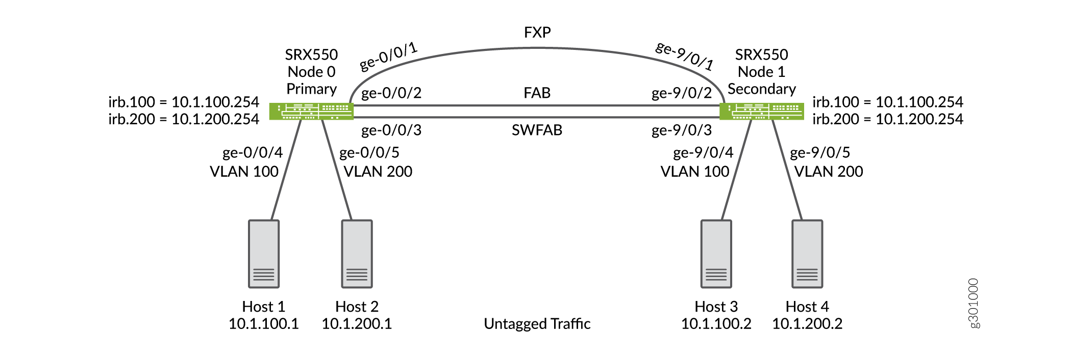
This example shows the configuration of a VLAN with members across node 0 and node 1.
Topology
Figure 21 shows the Layer 2 Ethernet switching across chassis cluster nodes using untagged traffic.
Configuration
Procedure
CLI Quick Configuration
To quickly configure this section of the example, copy the following
commands, paste them into a text file, remove any line breaks, change
any details necessary to match your network configuration, copy and
paste the commands into the CLI at the [edit] hierarchy
level, and then enter commit from configuration
mode.
set security zones security-zone trust host-inbound-traffic system-services all
set security zones security-zone trust interfaces irb.100
set security zones security-zone trust interfaces irb.200
set interfaces ge-0/0/4 unit 0 family ethernet-switching interface-mode access
set interfaces ge-0/0/4 unit 0 family ethernet-switching vlan members v100
set interfaces ge-0/0/5 unit 0 family ethernet-switching interface-mode access
set interfaces ge-0/0/5 unit 0 family ethernet-switching vlan members v200
set interfaces ge-9/0/4 unit 0 family ethernet-switching interface-mode access
set interfaces ge-9/0/4 unit 0 family ethernet-switching vlan members v100
set interfaces ge-9/0/5 unit 0 family ethernet-switching interface-mode access
set interfaces ge-9/0/5 unit 0 family ethernet-switching vlan members v200
set interfaces fab0 fabric-options member-interfaces ge-0/0/2
set interfaces fab1 fabric-options member-interfaces ge-9/0/2
set interfaces irb unit 100 family inet address 10.1.100.254/24
set interfaces irb unit 200 family inet address 10.1.200.254/24
set interfaces swfab0 fabric-options member-interfaces ge-0/0/3
set interfaces swfab1 fabric-options member-interfaces ge-9/0/3
set vlans v100 vlan-id 100
set vlans v100 l3-interface irb.100
set vlans v200 vlan-id 200
set vlans v200 l3-interface irb.200
Step-by-Step Procedure
To configure IRB and a VLAN:
-
Configure security zones.
{primary:node0} [edit security zones] user@host# set security-zone trust host-inbound-traffic system-services all user@host# set security-zone trust interfaces irb.100 user@host# set security-zone trust interfaces irb.200 -
Configure Ethernet switching on the node0 interfaces.
{primary:node0} [edit interfaces] user@host# set ge-0/0/4 unit 0 family ethernet-switching interface-mode access user@host# set ge-0/0/4 unit 0 family ethernet-switching vlan members v100 user@host# set ge-0/0/5 unit 0 family ethernet-switching interface-mode access user@host# set ge-0/0/5 unit 0 family ethernet-switching vlan members v200 user@host# set ge-9/0/4 unit 0 family ethernet-switching interface-mode access user@host# set ge-9/0/4 unit 0 family ethernet-switching vlan members v100 user@host# set ge-9/0/5 unit 0 family ethernet-switching interface-mode access user@host# set ge-9/0/5 unit 0 family ethernet-switching vlan members v200 -
Define the interfaces used for the fab connections (data plane links for RTOsync) by using physical ports from each node. These interfaces must be connected back-to-back, or through a Layer 2 infrastructure.
{primary:node0} [edit interfaces] user@host# set fab0 fabric-options member-interfaces ge-0/0/2 user@host# set fab1 fabric-options member-interfaces ge-9/0/2 -
configure a switching fabric interface on both nodes to configure Ethernet switching-related features on the nodes.
{primary:node0} [edit interfaces] user@host# set swfab0 fabric-options member-interfaces ge-0/0/3 user@host# set swfab1 fabric-options member-interfaces ge-9/0/3 -
Configure the irb interface.
{primary:node0} [edit interfaces] user@host# set irb unit 100 family inet address 10.1.100.254/24 user@host# set irb unit 200 family inet address 10.1.200.254/24 -
Create and associate a VLAN interface with the VLAN.
{primary:node0} [edit vlans] user@host# set v100 vlan-id 100 user@host# set v100 l3-interface irb.100 user@host# set v200 vlan-id 200 user@host# set v200 l3-interface irb.200 -
If you are done configuring the device, commit the configuration.
[edit]
user@host# commit
Results
From configuration mode, confirm your configuration by entering the
show security, show interfaces,
and show vlans commands. If the output does not display
the intended configuration, repeat the configuration instructions in
this example to correct the configuration.
[edit]
user@host# show security
zones {
    security-zone trust {
        host-inbound-traffic {
            system-services {
                all;
            }
        }
        interfaces {
            irb.100;
            irb.200;
        }
    }
}
[edit]
user@host# show interfaces
ge-0/0/4 {
    unit 0 {
        family ethernet-switching {
            interface-mode access;
            vlan {
                members v100;
            }
        }
    }
}
ge-0/0/5 {
    unit 0 {
        family ethernet-switching {
            interface-mode access;
            vlan {
                members v200;
            }
        }
    }
}
ge-9/0/4 {
    unit 0 {
        family ethernet-switching {
            interface-mode access;
            vlan {
                members v100;
            }
        }
    }
}
ge-9/0/5 {
    unit 0 {
        family ethernet-switching {
            interface-mode access;
            vlan {
                members v200;
            }
        }
    }
}
fab0 {
    fabric-options {
        member-interfaces {
            ge-0/0/2;
        }
    }
}
fab1 {
    fabric-options {
        member-interfaces {
            ge-9/0/2;
        }
    }
}
irb {
    unit 100 {
        family inet {
            address 10.1.100.254/24;
        }
    }
    unit 200 {
        family inet {
            address 10.1.200.254/24;
        }
    }
}
swfab0 {
    fabric-options {
        member-interfaces {
            ge-0/0/3;
        }
    }
}
swfab1 {
    fabric-options {
        member-interfaces {
            ge-9/0/3;
        }
    }
}
[edit]
user@host# show vlans
v100 {
    vlan-id 100;
    l3-interface irb.100;
}
v200 {
    vlan-id 200;
    l3-interface irb.200;
}
Verification
Verifying Untagged VLAN With IRB
Purpose
Verify that the configuration of untagged VLAN with IRB is working properly.
Action
From operational mode, enter the show chassis cluster
interfaces command.
user@host> show chassis cluster interfaces
Control link status: Up

Control interfaces:
    Index   Interface   Monitored-Status   Internal-SA   Security
    0       fxp1        Up                 Disabled      Disabled

Fabric link status: Up

Fabric interfaces:
    Name    Child-interface    Status                    Security
                               (Physical/Monitored)
    fab0    ge-0/0/2           Up   / Up                 Enabled
    fab0
    fab1    ge-9/0/2           Up   / Up                 Enabled
    fab1

Redundant-pseudo-interface Information:
    Name         Status      Redundancy-group
    lo0          Up          0
From operational mode, enter the show ethernet-switching
table command.
user@host> show ethernet-switching table
MAC flags (S - static MAC, D - dynamic MAC, L - locally learned, P - Persistent static, C - Control MAC
           SE - statistics enabled, NM - non configured MAC, R - remote PE MAC, O - ovsdb MAC)


Ethernet switching table : 4 entries, 4 learned
Routing instance : default-switch
    Vlan                MAC                 MAC         Age    Logical                NH        RTR
    name                address             flags              interface              Index     ID
    v100                08:81:f4:8a:eb:52   D             -   ge-9/0/4.0             0         0
    v100                08:81:f4:8a:eb:54   D             -   ge-0/0/4.0             0         0
    v200                08:81:f4:8a:eb:53   D             -   ge-9/0/5.0             0         0
    v200                08:81:f4:8a:eb:55   D             -   ge-0/0/5.0             0         0
From operational mode, enter the show arp
command.
user@host> show arp
MAC Address       Address         Name                      Interface               Flags
08:81:f4:8a:eb:54 10.1.100.1      10.1.100.1                irb.100                 none
08:81:f4:8a:eb:52 10.1.100.2      10.1.100.2                irb.100                 none
08:81:f4:8a:eb:55 10.1.200.1      10.1.200.1                irb.200                 none
08:81:f4:8a:eb:53 10.1.200.2      10.1.200.2                irb.200                 none
ec:3e:f7:c6:81:b0 30.17.0.2       30.17.0.2                 fab0.0                  permanent
f0:4b:3a:09:cb:30 30.18.0.1       30.18.0.1                 fab1.0                  permanent
ec:3e:f7:c6:80:81 130.16.0.1      130.16.0.1                fxp1.0                  none
Total entries: 7
From operational mode, enter the show ethernet-switching
interface command to view the information about
Ethernet switching interfaces.
user@host> show ethernet-switching interface
Routing Instance Name : default-switch
Logical Interface flags (DL - disable learning, AD - packet action drop,
                         LH - MAC limit hit, DN - interface down,
                         MMAS - Mac-move action shutdown,  AS - Autostate-exclude enabled,
                         SCTL - shutdown by Storm-control, MI - MAC+IP limit hit)

Logical         Vlan                   TAG   MAC    MAC+IP STP         Logical          Tagging
interface       members                      limit  limit  state       interface flags
ge-0/0/5.0                                   16383  8192                                untagged
                v200                   200   1024   1024   Forwarding                   untagged
Routing Instance Name : default-switch
Logical Interface flags (DL - disable learning, AD - packet action drop,
                         LH - MAC limit hit, DN - interface down,
                         MMAS - Mac-move action shutdown,  AS - Autostate-exclude enabled,
                         SCTL - shutdown by Storm-control, MI - MAC+IP limit hit)

Logical         Vlan                   TAG   MAC    MAC+IP STP         Logical          Tagging
interface       members                      limit  limit  state       interface flags
ge-0/0/4.0                                   16383  8192                                untagged
                v100                   100   1024   1024   Forwarding                   untagged
Routing Instance Name : default-switch
Logical Interface flags (DL - disable learning, AD - packet action drop,
                         LH - MAC limit hit, DN - interface down,
                         MMAS - Mac-move action shutdown,  AS - Autostate-exclude enabled,
                         SCTL - shutdown by Storm-control, MI - MAC+IP limit hit)

Logical         Vlan                   TAG   MAC    MAC+IP STP         Logical          Tagging
interface       members                      limit  limit  state       interface flags
ge-9/0/4.0                                   16383  8192                                untagged
                v100                   100   1024   1024   Forwarding                   untagged
Routing Instance Name : default-switch
Logical Interface flags (DL - disable learning, AD - packet action drop,
                         LH - MAC limit hit, DN - interface down,
                         MMAS - Mac-move action shutdown,  AS - Autostate-exclude enabled,
                         SCTL - shutdown by Storm-control, MI - MAC+IP limit hit)

Logical         Vlan                   TAG   MAC    MAC+IP STP         Logical          Tagging
interface       members                      limit  limit  state       interface flags
ge-9/0/5.0                                   16383  8192                                untagged
                v200                   200   1024   1024   Forwarding                   untagged
Meaning
The output shows the VLANs are configured and working fine.
Example: Configuring VLAN with Members Across Two Nodes on a Security Device
Requirements
This example uses the following hardware and software components:
configure a switching fabric interface on both nodes to configure Ethernet switching-related features on the nodes. See Example: Configuring Switch Fabric Interfaces to Enable Switching in Chassis Cluster Mode on a Security Device
SRX240 security device
Junos OS 12.3X48-D90
interface-mode is supported in 15.1X49 release.
port-mode is supported in 12.1 and 12.3X48 releases.
Overview
This example shows the configuration of a VLAN with members across node 0 and node 1.
Configuration
Procedure
CLI Quick Configuration
To quickly configure this section of the example,
copy the following commands, paste them into a text file, remove any
line breaks, change any details necessary to match your network configuration,
copy and paste the commands into the CLI at the [edit] hierarchy
level, and then enter commit from configuration mode.
set interfaces ge-0/0/3 unit 0 family ethernet-switching port-mode access
set interfaces ge-0/0/3 unit 0 family ethernet-switching vlan members vlan100
set interfaces ge0/0/4 unit 0 family ethernrt-switching port-mode access
set interfaces ge-0/0/4 unit 0 family ethernet-switching vlan members vlan100
set interfaces ge-7/0/5 unit 0 family ethernet-switching port-mode trunk
set interfaces ge-7/0/5 unit 0 family ethernet-switching vlan members vlan100
set interfaces vlan unit 100 family inet address 11.1.1.1/24
set vlans vlan100 vlan-id 100
set vlans vlan100 l3-interface vlan.100
Step-by-Step Procedure
To configure VLAN:
Configure Ethernet switching on the node0 interface.
{primary:node0} [edit]
user@host# set interfaces ge-0/0/3 unit 0 family ethernet-switching port-mode access
user@host# set interfaces ge0/0/4 unit 0 family ethernet-switching port-mode access
Configure Ethernet switching on the node1 interface.
{primary:node0} [edit]
user@host# set interfaces ge-7/0/5 unit 0 family ethernet-switching port-mode trunk
Create VLAN vlan100 with vlan-id 100.
{primary:node0} [edit]
user@host# set vlans vlan100 vlan-id 100
Add interfaces from both nodes to the VLAN.
{primary:node0} [edit]
user@host# set interfaces ge-0/0/3 unit 0 family ethernet-switching vlan members vlan100
user@host# set interfaces ge-0/0/4 unit 0 family ethernet-switching vlan members vlan100
user@host# set interfaces ge-7/0/5 unit 0 family ethernet-switching vlan members vlan100
Create a VLAN interface.
user@host# set interfaces vlan unit 100 family inet address 11.1.1.1/24
Associate an VLAN interface with the VLAN.
user@host# set vlans vlan100 l3-interface vlan.100
If you are done configuring the device, commit the configuration.
[edit]
user@host# commit
Results
From configuration mode, confirm your configuration
by entering the show vlans and show interfaces commands. If the output does not display the intended configuration,
repeat the configuration instructions in this example to correct the
configuration.
[edit]
user@host# show vlans
vlan100 {
     vlan-id 100;
    l3-interface vlan.100;
}
[edit]
user@host# show interfaces
ge-0/0/3 {
    unit 0 {
        family ethernet-switching {
            port-mode access;
            vlan {
                members vlan100;
            }
        }
    }
}
ge-0/0/4 {
    unit 0 {
        family ethernet-switching {
            port-mode access;
            vlan {
                members vlan100;
            }
        }
    }
}
ge-7/0/5 {
    unit 0 {
        family ethernet-switching {
            port-mode trunk;
            vlan {
                members vlan100;
            }
        }
    }
}
Verification
Verifying VLAN
Purpose
Verify that the configuration of VLAN is working properly.
Action
From operational mode, enter the show interfaces
terse ge-0/0/3 command to view the node 0 interface.
user@host> show interfaces terse ge-0/0/3
Interface               Admin Link Proto    Local                 Remote
ge-0/0/3                up    up
ge-0/0/3.0              up    up   eth-switch
From operational mode, enter the show interfaces terse
ge-0/0/4 command to view the node 0 interface.
user@host> show interfaces terse ge-0/0/4
Interface               Admin Link Proto    Local                 Remote
ge-0/0/4                up    up
ge-0/0/4.0              up    up   eth-switch
From operational mode, enter the show interfaces terse
ge-7/0/5 command to view the node1 interface.
user@host> show interfaces terse ge-7/0/5
Interface               Admin Link Proto    Local                 Remote
ge-7/0/5                up    up
ge-7/0/5.0              up    up   eth-switch
From operational mode, enter the show vlans command
to view the VLAN interface.
user@host> show vlans
Routing instance      VLAN name     Tag      Interfaces
default-switch        default        1
default-switch        vlan100        100     ge-0/0/3.0*
                                             ge-0/0/4.0*
                                             ge-7/0/5.0*
From operational mode, enter the show ethernet-switching
interface command to view the information about Ethernet switching
interfaces.
Routing Instance Name : default-switch
Logical Interface flags (DL - disable learning, AD - packet action drop,
                         LH - MAC limit hit, DN - interface down,
                         MMAS - Mac-move action shutdown,  AS - Autostate-exclude enabled,
                         SCTL - shutdown by Storm-control )

Logical         Vlan                   TAG   MAC    STP         Logical          Tagging
interface       members                      limit  state       interface flags
ge-0/0/3.0                                   16383              DN               untagged
                vlan100                100   1024   Discarding                   untagged
ge-0/0/4.0                                   16383              DN               untagged
                vlan100                100   1024   Discarding                   untagged
ge-7/0/5.0                                   16383              DN               tagged
                vlan100                100   1024   Discarding                   tagged
Meaning
The output shows the VLANs are configured and working fine.