Multiprotocol BGP
Understanding Multiprotocol BGP
Multiprotocol BGP (MP-BGP) is an extension to BGP that enables BGP to carry routing information for multiple network layers and address families. MP-BGP can carry the unicast routes used for multicast routing separately from the routes used for unicast IP forwarding.
To enable MP-BGP, you configure BGP to carry network layer reachability
information (NLRI) for address families other than unicast IPv4 by
including the family inet statement:
family inet {
    (any | flow | labeled-unicast | multicast | unicast) {
        accepted-prefix-limit {
            maximum number;
            teardown <percentage> <idle-timeout (forever | minutes)>;
            drop-excess <percentage>;
            hide-excess <percentage>;}
}
        <loops number>;
        prefix-limit {
            maximum number;
            teardown <percentage> <idle-timeout (forever | minutes)>;
            drop-excess <percentage>;
            hide-excess <percentage>;}
 }
        rib-group group-name;
        topology name {
            community {
                target identifier;
            }
        }
    }
}
To enable MP-BGP to carry NLRI for the IPv6 address family,
include the family inet6 statement:
family inet6 {
    (any | labeled-unicast | multicast | unicast) {
        accepted-prefix-limit {
            maximum number;
            teardown <percentage> <idle-timeout (forever | minutes)>;
            drop-excess <percentage>;
            hide-excess <percentage>;}
}
        <loops number>;
        prefix-limit {
            maximum number;
            teardown <percentage> <idle-timeout (forever | minutes)>;
            drop-excess <percentage>;
            hide-excess <percentage>;}
 }
        rib-group group-name;
    }
}
On routers only, to enable MP-BGP to carry Layer 3 virtual
private network (VPN) NLRI for the IPv4 address family, include the family inet-vpn statement:
family inet-vpn {
    (any | flow | multicast | unicast) {
        accepted-prefix-limit {
            maximum number;
            teardown <percentage> <idle-timeout (forever | minutes)>;
            drop-excess <percentage>;
            hide-excess <percentage>;}
}
        <loops number>;
        prefix-limit {
            maximum number;
            teardown <percentage> <idle-timeout (forever | minutes)>;
            drop-excess <percentage>;
            hide-excess <percentage>;}
}
        rib-group group-name;
    }
}
On routers only, to enable MP-BGP to carry Layer 3 VPN
NLRI for the IPv6 address family, include the family inet6-vpn statement:
family inet6-vpn {
    (any | multicast | unicast) {
        accepted-prefix-limit {
            maximum number;
            teardown <percentage> <idle-timeout (forever | minutes)>;
            drop-excess <percentage>;
            hide-excess <percentage>;}
}
        <loops number>;
        prefix-limit {
            maximum number;
            teardown <percentage> <idle-timeout (forever | minutes)>;
            drop-excess <percentage>;
            hide-excess <percentage>;}}
        rib-group group-name;
    }
}
On routers only, to enable MP-BGP to carry multicast VPN NLRI
for the IPv4 address family and to enable VPN signaling, include the family inet-mvpn statement:
family inet-mvpn {
    signaling {
        accepted-prefix-limit {
            maximum number;
            teardown <percentage> <idle-timeout (forever | minutes)>;
            drop-excess <percentage>;
            hide-excess <percentage>;}}
        <loops number>;
        prefix-limit {
            maximum number;
            teardown <percentage> <idle-timeout (forever | minutes)>;
            drop-excess <percentage>;
            hide-excess <percentage>;}}
    }
}
To enable MP-BGP to carry multicast VPN NLRI for the IPv6 address
family and to enable VPN signaling, include the family inet6-mvpn statement:
family inet6-mvpn {
    signaling {
        accepted-prefix-limit {
            maximum number;
            teardown <percentage> <idle-timeout (forever | minutes)>;
            drop-excess <percentage>;
            hide-excess <percentage>;}}
        <loops number>;
        prefix-limit {
            maximum number;
            teardown <percentage> <idle-timeout <forever | minutes>;
            drop-excess <percentage>;
            hide-excess <percentage>;}}
    }
}
For more information about multiprotocol BGP-based multicast VPNs, see the Junos OS Multicast Protocols User Guide.
For a list of hierarchy levels at which you can include these statements, see the statement summary sections for these statements.
If you change the address family specified in the [edit protocols bgp family]
hierarchy level, all current BGP sessions on the routing device are dropped and then
reestablished.
In Junos OS Release 9.6 and later, you can specify a loops value for a specific BGP address family.
By default, BGP peers carry only unicast routes used for unicast
forwarding purposes. To configure BGP peers to carry only multicast
routes, specify the multicast option. To configure BGP
peers to carry both unicast and multicast routes, specify the any option.
When MP-BGP is configured, BGP installs the MP-BGP routes into different routing tables. Each routing table is identified by the protocol family or address family indicator (AFI) and a subsequent address family identifier (SAFI).
The following list shows all possible AFI and SAFI combinations:
AFI=1, SAFI=1, IPv4 unicast
AFI=1, SAFI=2, IPv4 multicast
AFI=1, SAFI=128, L3VPN IPv4 unicast
AFI=1, SAFI=129, L3VPN IPv4 multicast
AFI=2, SAFI=1, IPv6 unicast
AFI=2, SAFI=2, IPv6 multicast
AFI=25, SAFI=65, BGP-VPLS/BGP-L2VPN
AFI=2, SAFI=128, L3VPN IPv6 unicast
AFI=2, SAFI=129, L3VPN IPv6 multicast
AFI=1, SAFI=132, RT-Constrain
AFI=1, SAFI=133, Flow-spec
AFI=1, SAFI=134, Flow-spec
AFI=3, SAFI=128, CLNS VPN
AFI=1, SAFI=5, NG-MVPN IPv4
AFI=2, SAFI=5, NG-MVPN IPv6
AFI=1, SAFI=66, MDT-SAFI
AFI=1, SAFI=4, labeled IPv4
AFI=2, SAFI=4, labeled IPv6 (6PE)
Routes installed in the inet.2 routing table can only be exported to MP-BGP peers because they use the SAFI, identifying them as routes to multicast sources. Routes installed in the inet.0 routing table can only be exported to standard BGP peers.
The inet.2 routing table should be a subset of the routes that
you have in inet.0, since it is unlikely that you would have a route
to a multicast source to which you could not send unicast traffic.
The inet.2 routing table stores the unicast routes that are used for
multicast reverse-path-forwarding checks and the additional reachability
information learned by MP-BGP from the NLRI multicast updates. An
inet.2 routing table is automatically created when you configure MP-BGP
(by setting NLRI to any).
When you enable MP-BGP, you can do the following:
- Limiting the Number of Prefixes Received on a BGP Peer Session
- Limiting the Number of Prefixes Accepted on a BGP Peer Session
- Configuring BGP Routing Table Groups
- Resolving Routes to PE Routing Devices Located in Other ASs
- Allowing Labeled and Unlabeled Routes
Limiting the Number of Prefixes Received on a BGP Peer Session
You can limit the number of prefixes received on a BGP peer session, and log rate-limited messages when the number of injected prefixes exceeds a set limit. You can also tear down the peering when the number of prefixes exceeds the limit.
To configure a limit to the number of prefixes that can be received
on a BGP session, include the prefix-limit statement:
prefix-limit {
    maximum number;
    teardown <percentage> <idle-timeout (forever | minutes)>;
    drop-excess <percentage>;
    hide-excess <percentage>;
}
For a list of hierarchy levels at which you can include this statement, see the statement summary section for this statement.
For maximum number, specify
a value in the range from 1 through 4,294,967,295. When
the specified maximum number of prefixes is exceeded, a system log
message is sent.
If you include the teardown statement, the session is torn down when the maximum
number of prefixes is exceeded. If you specify a percentage, messages are logged
when the number of prefixes exceeds that percentage of the specified maximum limit.
After the session is torn down, it is reestablished in a short time (unless you
include the idle-timeout statement). If you include the
idle-timeout statement, the session can be kept down for a
specified amount of time, or forever. If you specify forever, the
session is reestablished only after the you issue a clear bgp
neighbor command. If you include the drop-excess
<percentage> option, the excess routes are
dropped when the maximum number of prefixes is reached. If you specify a percentage,
the routes are logged when the number of prefixes exceeds that percentage value of
the maximum number. If you include the hide-excess
<percentage> option, the excess routes are
hidden when the maximum number of prefixes is reached. If you specify a percentage,
the routes are logged when the number of prefixes exceeds that percentage value of
the maximum number. If the percentage is modified, the routes are re-evaluated
automatically. If the active routes drop below the specified percentage, those
routes are kept as hidden.
In Junos OS Release 9.2 and later, you can alternatively configure a limit to the number of prefixes that can be accepted on a BGP peer session. For more information, see Limiting the Number of Prefixes Accepted on a BGP Peer Session.
Limiting the Number of Prefixes Accepted on a BGP Peer Session
In Junos OS Release 9.2 and later, you can limit the number of prefixes that can be accepted on a BGP peer session. When that specified limit is exceeded, a system log message is sent. You can also specify to reset the BGP session if the limit to the number of specified prefixes is exceeded.
To configure a limit to the number of prefixes that can be accepted
on a BGP peer session, include the accepted-prefix-limit statement:
accepted-prefix-limit { maximum number; teardown <percentage> <idle-timeout (forever | minutes)>; drop <percentage>; hide <percentage>; }
For a list of hierarchy levels at which you can include this statement, see the statement summary section for this statement.
For maximum number, specify a value in the range from 1 through 4,294,967,295.
Include the teardown statement to reset the BGP peer session when the number of
accepted prefixes exceeds the configured limit. You can also include a percentage
value from 1 through 100 to have a system log message sent when the number of
accepted prefixes exceeds that percentage of the maximum limit. By default, a BGP
session that is reset is reestablished within a short time. Include the
idle-timeout statement to prevent the BGP session from being
reestablished for a specified period of time. You can configure a timeout value
from 1 through 2400 minutes. Include the forever option to
prevent the BGP session from being reestablished until you issue the clear
bgp neighbor command. If you include the drop-excess
<percentage> statement and specify a
percentage, the excess routes are dropped when the number of prefixes exceeds the
percentage. If you include the hide-excess
<percentage> statement and specify a
percentage, the excess routes are hidden when the number of prefixes exceeds the
percentage. If the percentage is modified, the routes are re-evaluated
automatically.
When nonstop active routing (NSR) is enabled and a switchover
to a backup Routing Engine occurs, BGP peers that are down are automatically
restarted. The peers are restarted even if the idle-timeout forever statement is configured.
Alternatively, you can configure a limit to the number of prefixes that can be received (as opposed to accepted) on a BGP peer session. For more information, see Limiting the Number of Prefixes Received on a BGP Peer Session.
Configuring BGP Routing Table Groups
When a BGP session receives a unicast or multicast NLRI, it installs the route in the appropriate table (inet.0 or inet6.0 for unicast, and inet.2 or inet6.2 for multicast). To add unicast prefixes to both the unicast and multicast tables, you can configure BGP routing table groups. This is useful if you cannot perform multicast NLRI negotiation.
To configure BGP routing table groups, include the rib-group statement:
rib-group group-name;
For a list of hierarchy levels at which you can include this statement, see the statement summary section for this statement.
Resolving Routes to PE Routing Devices Located in Other ASs
You can allow labeled routes to be placed in the inet.3 routing table for route resolution. These routes are then resolved for provider edge (PE) routing device connections where the remote PE is located across another autonomous system (AS). For a PE routing device to install a route in the VPN routing and forwarding (VRF) routing instance, the next hop must resolve to a route stored within the inet.3 table.
To resolve routes into the inet.3 routing table, include
the resolve-vpn statement:
resolve-vpn group-name;
For a list of hierarchy levels at which you can include this statement, see the statement summary section for this statement.
Allowing Labeled and Unlabeled Routes
You can allow both labeled and unlabeled routes to be exchanged in a single session. The labeled routes are placed in the inet.3 or inet6.3 routing table, and both labeled and unlabeled unicast routes can be sent to or received by the routing device.
To allow both labeled and unlabeled routes to be exchanged,
include the rib statement:
rib (inet.3 | inet6.3);
For a list of hierarchy levels at which you can include this statement, see the statement summary section for this statement.
Example: Configuring IPv6 BGP Routes over IPv4 Transport
This example demonstrates how to export both IPv6 and IPv4 prefixes over an IPv4 connection where both sides are configured with an IPv4 interface.
Requirements
No special configuration beyond device initialization is required before you configure this example.
Overview
Keep the following in mind when exporting IPv6 BGP prefixes:
BGP derives next-hop prefixes using the IPv4-mapped IPv6 prefix. For example, the IPv4 next-hop prefix
10.19.1.1translates to the IPv6 next-hop prefix ::ffff:10.19.1.1.Note:There must be an active route to the IPv4-mapped IPv6 next hop to export IPv6 BGP prefixes.
An IPv6 connection must be configured over the link. The connection must be either an IPv6 tunnel or a dual-stack configuration. Dual stacking is used in this example.
When configuring IPv4-mapped IPv6 prefixes, use a mask that is longer than 96 bits.
Configure a static route if you want to use normal IPv6 prefixes. This example uses static routes.
Figure 1 shows the sample topology.
Configuration
CLI Quick Configuration
To quickly configure this example, copy the
following commands, paste them into a text file, remove any line breaks,
change any details necessary to match your network configuration,
and then copy and paste the commands into the CLI at the [edit] hierarchy level.
Device R1
set interfaces fe-1/2/0 unit 1 family inet address 192.168.10.1/24 set interfaces fe-1/2/0 unit 1 family inet6 address ::ffff:192.168.10.1/120 set interfaces lo0 unit 1 family inet address 10.10.10.1/32 set protocols bgp group ext type external set protocols bgp group ext family inet unicast set protocols bgp group ext family inet6 unicast set protocols bgp group ext export send-direct set protocols bgp group ext export send-static set protocols bgp group ext peer-as 200 set protocols bgp group ext neighbor 192.168.10.10 set policy-options policy-statement send-direct term 1 from protocol direct set policy-options policy-statement send-direct term 1 then accept set policy-options policy-statement send-static term 1 from protocol static set policy-options policy-statement send-static term 1 then accept set routing-options rib inet6.0 static route ::ffff:192.168.20.0/120 next-hop ::ffff:192.168.10.10 set routing-options static route 192.168.20.0/24 next-hop 192.168.10.10 set routing-options autonomous-system 100
Device R2
set interfaces fe-1/2/0 unit 2 family inet address 192.168.10.10/24 set interfaces fe-1/2/0 unit 2 family inet6 address ::ffff:192.168.10.10/120 set interfaces fe-1/2/1 unit 3 family inet address 192.168.20.21/24 set interfaces fe-1/2/1 unit 3 family inet6 address ::ffff:192.168.20.21/120 set interfaces lo0 unit 2 family inet address 10.10.0.1/32 set protocols bgp group ext type external set protocols bgp group ext family inet unicast set protocols bgp group ext family inet6 unicast set protocols bgp group ext export send-direct set protocols bgp group ext export send-static set protocols bgp group ext neighbor 192.168.10.1 peer-as 100 set protocols bgp group ext neighbor 192.168.20.1 peer-as 300 set policy-options policy-statement send-direct term 1 from protocol direct set policy-options policy-statement send-direct term 1 then accept set policy-options policy-statement send-static term 1 from protocol static set policy-options policy-statement send-static term 1 then accept set routing-options autonomous-system 200
Device R3
set interfaces fe-1/2/0 unit 4 family inet address 192.168.20.1/24 set interfaces fe-1/2/0 unit 4 family inet6 address ::ffff:192.168.20.1/120 set interfaces lo0 unit 3 family inet address 10.10.20.1/32 set protocols bgp group ext type external set protocols bgp group ext family inet unicast set protocols bgp group ext family inet6 unicast set protocols bgp group ext export send-direct set protocols bgp group ext export send-static set protocols bgp group ext peer-as 200 set protocols bgp group ext neighbor 192.168.20.21 set policy-options policy-statement send-direct term 1 from protocol direct set policy-options policy-statement send-direct term 1 then accept set policy-options policy-statement send-static term 1 from protocol static set policy-options policy-statement send-static term 1 then accept set routing-options rib inet6.0 static route ::ffff:192.168.10.0/120 next-hop ::ffff:192.168.20.21 set routing-options static route 192.168.10.0/24 next-hop 192.168.20.21 set routing-options autonomous-system 300
Configuring Device R1
Step-by-Step Procedure
The following example requires you to navigate various levels in the configuration hierarchy. For information about navigating the CLI, see Using the CLI Editor in Configuration Mode in the Junos OS CLI User Guide.
To configure Device R1:
Configure the interfaces, including both an IPv4 address and an IPv6 address.
[edit interfaces] user@R1# set fe-1/2/0 unit 1 family inet address 192.168.10.1/24 user@R1# set fe-1/2/0 unit 1 family inet6 address ::ffff:192.168.10.1/120 user@R1# set lo0 unit 1 family inet address 10.10.10.1/32
Configure EBGP.
[edit protocols bgp group ext] user@R1# set type external user@R1# set export send-direct user@R1# set export send-static user@R1# set peer-as 200 user@R1# set neighbor 192.168.10.10
-
Enable BGP to carry IPv4 unicast and IPv6 unicast routes.
[edit protocols bgp group ext] user@R1# set family inet unicast user@R1# set family inet6 unicast
IPv4 unicast routes are enabled by default. However, when you configure other NLRI address families, IPv4 unicast must be explicitly configured.
-
Configure the routing policy.
[edit policy-options] user@R1# set policy-statement send-direct term 1 from protocol direct user@R1# set policy-statement send-direct term 1 then accept user@R1# set policy-statement send-static term 1 from protocol static user@R1# set policy-statement send-static term 1 then accept
Configure some static routes.
[edit routing-options] user@R1# set rib inet6.0 static route ::ffff:192.168.20.0/120 next-hop ::ffff:192.168.10.10 user@R1# set static route 192.168.20.0/24 next-hop 192.168.10.10
Configure the autonomous system (AS) number.
[edit routing-options] user@R1# set autonomous-system 100
Results
From configuration mode, confirm your configuration
by entering the show interfaces, show policy-options, show protocols, and show routing-options commands.
If the output does not display the intended configuration, repeat
the instructions in this example to correct the configuration.
user@R1# show interfaces
fe-1/2/0 {
unit 1 {
family inet {
address 192.168.10.1/24;
}
family inet6 {
address ::ffff:192.168.10.1/120;
}
}
}
lo0 {
unit 1 {
family inet {
address 10.10.10.1/32;
}
}
}
user@R1# show policy-options
policy-statement send-direct {
term 1 {
from protocol direct;
then accept;
}
}
policy-statement send-static {
term 1 {
from protocol static;
then accept;
}
}
user@R1# show protocols
bgp {
group ext {
type external;
family inet {
unicast;
}
family inet6 {
unicast;
}
export [ send-direct send-static ];
peer-as 200;
neighbor 192.168.10.10;
}
}
user@R1# show routing-options
rib inet6.0 {
static {
route ::ffff:192.168.20.0/120 next-hop ::ffff:192.168.10.10;
}
}
static {
route 192.168.20.0/24 next-hop 192.168.10.10;
}
autonomous-system 100;
If you are done configuring the device, enter commit from configuration mode. Repeat the configuration on Device R2 and Device R3, changing the interface names and IP addresses, as needed.
Verification
Confirm that the configuration is working properly.
Checking the Neighbor Status
Purpose
Make sure that BGP is enabled to carry IPv6 unicast routes.
Action
From operational mode, enter the show bgp neighbor command.
user@R2> show bgp neighbor
Peer: 192.168.10.1+179 AS 100 Local: 192.168.10.10+54226 AS 200
Type: External State: Established Flags: <Sync>
Last State: OpenConfirm Last Event: RecvKeepAlive
Last Error: None
Export: [ send-direct send-static ]
Options: <Preference AddressFamily PeerAS Refresh>
Address families configured: inet-unicast inet6-unicast
Holdtime: 90 Preference: 170
Number of flaps: 0
Peer ID: 10.10.10.1 Local ID: 10.10.0.1 Active Holdtime: 90
Keepalive Interval: 30 Peer index: 0
BFD: disabled, down
Local Interface: fe-1/2/0.2
NLRI for restart configured on peer: inet-unicast inet6-unicast
NLRI advertised by peer: inet-unicast inet6-unicast
NLRI for this session: inet-unicast inet6-unicast
Peer supports Refresh capability (2)
Stale routes from peer are kept for: 300
Peer does not support Restarter functionality
NLRI that restart is negotiated for: inet-unicast inet6-unicast
NLRI of received end-of-rib markers: inet-unicast inet6-unicast
NLRI of all end-of-rib markers sent: inet-unicast inet6-unicast
Peer supports 4 byte AS extension (peer-as 100)
Peer does not support Addpath
Table inet.0 Bit: 10000
RIB State: BGP restart is complete
Send state: in sync
Active prefixes: 1
Received prefixes: 3
Accepted prefixes: 2
Suppressed due to damping: 0
Advertised prefixes: 4
Table inet6.0 Bit: 20000
RIB State: BGP restart is complete
Send state: in sync
Active prefixes: 0
Received prefixes: 1
Accepted prefixes: 1
Suppressed due to damping: 0
Advertised prefixes: 2
Last traffic (seconds): Received 24 Sent 12 Checked 60
Input messages: Total 132 Updates 6 Refreshes 0 Octets 2700
Output messages: Total 133 Updates 3 Refreshes 0 Octets 2772
Output Queue[0]: 0
Output Queue[1]: 0
Peer: 192.168.20.1+179 AS 300 Local: 192.168.20.21+54706 AS 200
Type: External State: Established Flags: <Sync>
Last State: OpenConfirm Last Event: RecvKeepAlive
Last Error: None
Export: [ send-direct send-static ]
Options: <Preference AddressFamily PeerAS Refresh>
Address families configured: inet-unicast inet6-unicast
Holdtime: 90 Preference: 170
Number of flaps: 0
Peer ID: 10.10.20.1 Local ID: 10.10.0.1 Active Holdtime: 90
Keepalive Interval: 30 Peer index: 1
BFD: disabled, down
Local Interface: fe-1/2/1.3
NLRI for restart configured on peer: inet-unicast inet6-unicast
NLRI advertised by peer: inet-unicast inet6-unicast
NLRI for this session: inet-unicast inet6-unicast
Peer supports Refresh capability (2)
Stale routes from peer are kept for: 300
Peer does not support Restarter functionality
NLRI that restart is negotiated for: inet-unicast inet6-unicast
NLRI of received end-of-rib markers: inet-unicast inet6-unicast
NLRI of all end-of-rib markers sent: inet-unicast inet6-unicast
Peer supports 4 byte AS extension (peer-as 300)
Peer does not support Addpath
Table inet.0 Bit: 10000
RIB State: BGP restart is complete
Send state: in sync
Active prefixes: 1
Received prefixes: 3
Accepted prefixes: 2
Suppressed due to damping: 0
Advertised prefixes: 4
Table inet6.0 Bit: 20000
RIB State: BGP restart is complete
Send state: in sync
Active prefixes: 0
Received prefixes: 1
Accepted prefixes: 1
Suppressed due to damping: 0
Advertised prefixes: 2
Last traffic (seconds): Received 1 Sent 15 Checked 75
Input messages: Total 133 Updates 6 Refreshes 0 Octets 2719
Output messages: Total 131 Updates 3 Refreshes 0 Octets 2734
Output Queue[0]: 0
Output Queue[1]: 0Meaning
The various occurrences of inet6-unicast in the output shows that BGP is enabled to carry IPv6 unicast routes.
Checking the Routing Table
Purpose
Make sure that Device R2 has BGP routes in its inet6.0 routing table.
Action
From operational mode, enter the show route protocol
bgp inet6.0 command.
user@R2> show route protocol bgp table inet6.0
inet6.0: 7 destinations, 10 routes (7 active, 0 holddown, 0 hidden)
+ = Active Route, - = Last Active, * = Both
::ffff:192.168.10.0/120 [BGP/170] 01:03:49, localpref 100, from 192.168.20.1
AS path: 300 I
> to ::ffff:192.168.20.21 via fe-1/2/1.3
::ffff:192.168.20.0/120 [BGP/170] 01:03:53, localpref 100, from 192.168.10.1
AS path: 100 I
> to ::ffff:192.168.10.10 via fe-1/2/0.2Advertising IPv4 Routes over BGP IPv6 Sessions Overview
In an IPv6 network, BGP typically advertises IPv6 network layer reachability information over an IPv6 session between BGP peers. In earlier releases, Junos OS supported the exchange of inet6 unicast, inet6 multicast, or inet6 labeled-unicast address families only. This feature allows the exchange of all BGP address families. In a dual-stack environment that has IPv6 in its core. this feature enables BGP to advertise IPv4 unicast reachability with IPv4 next hop over an IPv6 BGP session.
This feature is for BGP IPv6 sessions only, where IPv4 is configured
at both endpoints. The local-ipv4-address can be a loopback
address or any ipv4 address for an IBGP or multiple-hop EBGP session.
For single-hop external BGP speakers that are not part of BGP confederations,
if the configured local IPv4 address is not directly connected, the
BGP session is closed and remains idle and an error is generated,
which is displayed in the output of the show bgp neighbor command.
To enable IPv4 route advertising over IPv6 session, configure local-ipv4-address as follows:
[edit protocols bgp family inet unicast] local-ipv4-address local ipv4 address;
You cannot configure this feature for the inet6 unicast, inet6 multicast, or inet6 labeled-unicast address families because BGP already has the capability to advertise these address families over an IPv6 BGP session.
The configured local-ipv4-address is used only when
BGP advertises routes with self-next hop. When IBGP advertises routes
learned from EBGP peers or the route reflector advertises BGP routes
to its clients, BGP does not change the route next hop, ignores the
configured local-ipv4-address, and uses the original IPv4
next hop.
See Also
Example: Advertising IPv4 Routes over IPv6 BGP Sessions
This example shows how to advertise IPv4 routes over IPv6 BGP session.In a dual-stack environment that has IPv6 in its core, there is a need to reach remote IPv4 hosts. Therefore, BGP advertises IPv4 routes with IPv4 next hops to BGP peers over BGP sessions using IPv6 source and destination addresses. This feature enables BGP to advertise IPv4 unicast reachability with IPv4 next hop over IPv6 BGP sessions.
Requirements
This example uses the following hardware and software components:
-
Three routers with dual stacking capability
-
Junos OS Release 16.1 or later running on all the devices
Before you enable IPv4 advertisements over IPv6 BGP sessions, be sure to:
-
Configure the device interfaces.
-
Configure dual stacking on all devices.
Overview
Beginning with Release 16.1, Junos OS allows BGP to advertise
IPv4 unicast reachability with IPv4 next hop over an IPv6 BGP session.
In earlier Junos OS releases, BGP could advertise only inet6 unicast,
inet6 multicast and inet6 labeled unicast address families over IPv6
BGP sessions. This feature allows BGP to exchange all BGP address
families over an IPv6 session. You can enable BGP to advertise IPv4
routes with IPv4 next hops to BGP peers over IPv6 session. The configured local-ipv4-address is used only when BGP advertises routes
with self-next hop.
You cannot configure this feature for the inet6 unicast, inet6 multicast, or inet6 labeled-unicast address families because BGP already has the capability to advertise these address families over an IPv6 BGP session.
Topology
In Figure 2, an IPv6 external
BGP session is running between Routers R1 and R2. An IPv6 IBGP session
is established between Router R2 and Router R3. IPv4 static routes
are redistributed to the BGP on R1. To redistribute the IPv4 routes
over the IPv6 BGP session, the new feature must be enabled on all
routers at the [edit protocols bgp address family] hierarchy
level.
Configuration
CLI Quick Configuration
To quickly configure this example, copy the
following commands, paste them into a text file, remove any line breaks,
change any details necessary to match your network configuration,
copy and paste the commands into the CLI at the [edit] hierarchy level, and then enter commit from configuration
mode.
Router R1
set interfaces ge-0/0/0 unit 0 description R1->R2 set interfaces ge-0/0/0 unit 0 family inet address 140.1.1.1/24 set interfaces ge-0/0/0 unit 0 family inet6 address ::140.1.1.1/126 set interfaces lo0 unit 0 family inet6 address 1::1/128 set routing-options static route 11.1.1.1/32 discard set routing-options static route 11.1.1.2/32 discard set routing-options autonomous-system 64497 set protocols bgp group ebgp-v6 type external set protocols bgp group ebgp-v6 export p1 set protocols bgp group ebgp-v6 peer-as 64496 set protocols bgp group ebgp-v6 neighbor ::140.1.1.2 description R2 set protocols bgp group ebgp-v6 neighbor ::140.1.1.2 family inet unicast local-ipv4-address 140.1.1.1 set policy-options policy-statement p1 from protocol static set policy-options policy-statement p1 then accept
Router R2
set interfaces ge-0/0/0 unit 0 description R2->R1 set interfaces ge-0/0/0 unit 0 family inet address 140.1.1.2/24 set interfaces ge-0/0/0 unit 0 family inet6 address ::140.1.1.2/126 set interfaces ge-0/0/1 unit 0 description R2->R3 set interfaces ge-0/0/1 unit 0 family inet address 150.1.1.1/24 set interfaces ge-0/0/1 unit 0 family inet6 address ::150.1.1.1/126 set interfaces lo0 unit 0 family inet6 address 1::2/128 set routing-options autonomous-system 64496 set protocols bgp group ibgp-v6 type internal set protocols bgp group ibgp-v6 export change-nh set protocols bgp group ibgp-v6 neighbor ::150.1.1.2 description R3 set protocols bgp group ibgp-v6 neighbor ::150.1.1.2 family inet unicast local-ipv4-address 150.1.1.1 set protocols bgp group ebgp-v6 type external set protocols bgp group ebgp-v6 peer-as 64497 set protocols bgp group ebgp-v6 neighbor ::140.1.1.1 description R1 set protocols bgp group ebgp-v6 neighbor ::140.1.1.1 family inet unicast local-ipv4-address 140.1.1.2 set policy-options policy-statement change-nh from protocol bgp set policy-options policy-statement change-nh then next-hop self set policy-options policy-statement change-nh then accept
Router R3
set interfaces ge-0/0/0 unit 0 description R3->R2 set interfaces ge-0/0/0 unit 0 family inet address 150.1.1.2/24 set interfaces ge-0/0/0 unit 0 family inet6 address ::150.1.1.2/126 set interfaces lo0 unit 0 family inet6 address 1::3/128 set routing-options autonomous-system 64496 set protocols bgp group ibgp-v6 type internal set protocols bgp group ibgp-v6 neighbor ::150.1.1.1 description R2 set protocols bgp group ibgp-v6 neighbor ::150.1.1.1 family inet unicast local-ipv4-address 150.1.1.2
Configuring Router R1
Step-by-Step Procedure
The following example requires that you navigate various levels in the configuration hierarchy. For information about navigating the CLI, see Using the CLI Editor in Configuration Mode in the CLI User Guide.
To configure Router R1:
Repeat this procedure for other routers after modifying the appropriate interface names, addresses, and other parameters.
-
Configure the interfaces with IPv4 and IPv6 addresses.
[edit interfaces] user@R1# set ge-0/0/0 unit 0 description R1->R2 user@R1# set ge-0/0/0 unit 0 family inet address 140.1.1.1/24 user@R1# set ge-0/0/0 unit 0 family inet6 address ::140.1.1.1/126
-
Configure the loopback address.
[edit interfaces] user@R1# set lo0 unit 0 family inet6 address 1::1/128
-
Configure an IPv4 static route that needs to be advertised.
[edit routing-options] user@R1# set static route 11.1.1.1/32 discard user@R1# set static route 11.1.1.2/32 discard
-
Configure the autonomous system for BGP hosts.
[edit routing-options] user@R1# set autonomous-system 64497
-
Configure EBGP on the external edge routers.
[edit protocols] user@R1# set bgp group ebgp-v6 type external user@R1# set bgp group ebgp-v6 peer-as 64496 user@R1# set bgp group ebgp-v6 neighbor ::140.1.1.2 description R2
-
Enable the feature to advertise IPv4 adddress 140.1.1.1 over BGP IPv6 sessions.
[edit protocols] user@R1# set bgp group ebgp-v6 neighbor ::140.1.1.2 family inet unicast local-ipv4-address 140.1.1.1
-
Define a policy p1 to accept all static routes.
[edit policy-options] user@R1# set policy-statement p1 from protocol static user@R1# set policy-statement p1 then accept
-
Apply the policy p1 on EBGP group ebgp-v6.
[edit protocols] user@R1# set bgp group ebgp-v6 export p1
Results
From configuration mode, confirm your configuration by entering the show interfaces, show protocols, show routing-options, and show policy-options commands. If the output does not display the intended configuration, repeat the instructions in this example to correct the configuration.
[edit]
user@R1# show interfaces
ge-0/0/0 {
unit 0 {
description R1->R2;
family inet {
address 140.1.1.1/24;
}
family inet6 {
address ::140.1.1.1/126;
}
}
lo0 {
unit 0 {
family inet {
address 1::1/128;
}
}
}
}[edit]
user@R1# show protocols
bgp {
group ebgp-v6 {
type external;
export p1;
peer-as 64496;
neighbor ::140.1.1.2 {
description R2;
family inet {
unicast {
local-ipv4-address 140.1.1.1;
}
}
}
}
}[edit]
user@R1# show routing-options
static {
route 11.1.1.1/32 discard;
route 11.1.1.2/32 discard;
}
autonomous-system 64497;[edit]
user@R1# show policy-options
policy-statement p1 {
from {
protocol static;
}
then accept;
}If you are done configuring the device, commit the configuration.
user@R1# commit
Verification
Confirm that the configuration is working properly.
- Verifying That the BGP Session Is Up
- Verifying That the IPv4 address Is Being Advertised
- Verifying That the BGP Neighbor Router R2 Receives the Advertised IPv4 Address
Verifying That the BGP Session Is Up
Purpose
Verify that BGP is running on the configured interfaces and that the BGP session is active for each neighbor address.
Action
From operational mode, run the show bgp summary command on Router R1.
user@R1> show bgp summary
Groups: 1 Peers: 1 Down peers: 0
Table Tot Paths Act Paths Suppressed History Damp State Pending
inet.0
0 0 0 0 0 0
Peer AS InPkt OutPkt OutQ Flaps Last Up/Dwn State|#Active/Received/Accepted/Damped...
::140.1.1.2 64496 4140 4158 0 0 1d 7:10:36 0/0/0/0 0/0/0/0Meaning
The BGP session is up and running, and BGP peering is established.
Verifying That the IPv4 address Is Being Advertised
Purpose
Verify that the configured IPv4 address is being advertised by Router R1 to the configured BGP neighbors.
Action
From operational mode, run the show route advertising-protocol bgp ::150.1.1.2 command on Router R1.
user@R1> show route advertising-protocol bgp ::150.1.1.2 inet.0: 48 destinations, 48 routes (48 active, 0 holddown, 0 hidden) Prefix Nexthop MED Lclpref AS path * 11.1.1.1/32 Self 64497 64497 I * 11.1.1.2/32 Self 64497 64497 I
Meaning
The IPv4 static route is being advertised to the BGP neighbor Router R2.
Verifying That the BGP Neighbor Router R2 Receives the Advertised IPv4 Address
Purpose
Verify that Router R2 receives the IPv4 address that Router R1 is advertising to the BGP neighbor over IPv6.
Action
user@R2> show route receive-protocol bgp ::140.1.1.1 inet.0: 48 destinations, 48 routes (48 active, 0 holddown, 0 hidden) Prefix Nexthop MED Lclpref AS path * 11.1.1.1/32 140.1.1.1 64497 I * 11.1.1.2/32 140.1.1.1 64497 I iso.0: 1 destinations, 1 routes (1 active, 0 holddown, 0 hidden) inet6.0: 9 destinations, 10 routes (9 active, 0 holddown, 0 hidden)
Meaning
The presence of the static IPv4 route in Router R2’s routing table indicates that it is receiving the advertised IPv4 routes from Router R1.
Understanding Redistribution of IPv4 Routes with IPv6 Next Hop into BGP
In a network that predominantly transports IPv6 traffic there is a need to route IPv4 routes when required. For example, an Internet Service Provider that has an IPv6-only network, but has customers who still route IPv4 traffic. In this case, it is necessary to cater to such customers and forward IPv4 traffic over an IPv6 network. As described in RFC 5549, Advertising IPv4 Network Layer Reachability Information with an IPv6 Next Hop IPv4 traffic is tunneled from customer premises equipment (CPE) devices to IPv4-over-IPv6 gateways. These gateways are announced to CPE devices through anycast addresses. The gateway devices then create dynamic IPv4-over-IPv6 tunnels to remote CPE devices and advertise IPv4 aggregate routes to steer traffic.
Dynamic IPv4-over-IPv6 tunnel feature does not support unified ISSU in Junos OS Release 17.3R1.
Route reflectors (RRs) with a programmable interface are connected through IBGP to the gateway routers and host routes with IPv6 address as the next hop. These RRs advertise the IPv4 /32 addresses to inject the tunnel information into the network. The gateway routers create dynamic IPv4-over-IPv6 tunnels to the remote customer provider edge. The gateway router also advertises the IPv4 aggregate routes to steer traffic. The RR then advertises the tunnel source routes to the ISP. When the RR removes the tunnel route, BGP also withdraws the route causing the tunnel to be torn down and the CPE to be unreachable. The gateway router also withdraws the IPv4 aggregate routes and IPv6 tunnel source routes when all the aggregate routes contributor routes are removed. The gateway router sends route withdraw when the anchor Packet Forwarding Engine line card goes down, so that it will redirect traffic to other gateway routers.
The following extensions are introduced to support IPv4 routes with an IPv6 next hop:
- BGP Next Hop Encoding
- Tunnel Localization
- Tunnel Handling
- Tunnel Load Balancing and Anchor Packet Forwarding Engine Failure Handling
- Tunnel Loopback Stream Statistics
BGP Next Hop Encoding
BGP is extended with next hop encoding capability that is used to send IPv4 routes with IPv6 next hops. If this capability is not available on the remote peer, BGP groups the peers based on this encoding capability and removes BGP family without encoding capability from the negotiated network layer reachability information (NLRI) list. Junos OS allows only one resolution table such as inet.0. To permit IPv4 BGP routes with IPv6 next hops BGP creates a new resolution tree. This feature allows a Junos OS routing table to have multiple resolution trees.
Besides RFC 5549, Advertising IPv4 Network Layer Reachability Information with an IPv6 Next Hop a new encapsulation community specified in RFC 5512, The BGP Encapsulation Subsequent Address Family Identifier (SAFI) and the BGP Tunnel Encapsulation Attribute is introduced to determine the address family of the next-hop address. The encapsulation community indicates the type of tunnels that the ingress node needs to create. When BGP receives IPv4 routes with IPv6 next hop address and the V4oV6 encapsulation community, then BGP creates IPv4-over-IPv6 dynamic tunnels. When BGP receives routes without the encapsulation community, BGP routes are resolved without creating the V4oV6 tunnel.
A new policy action dynamic-tunnel-attributes dyan-attribute
is available at the [edit policy-statement policy name term then] hierarchy level to support
the new extended encapsulation.
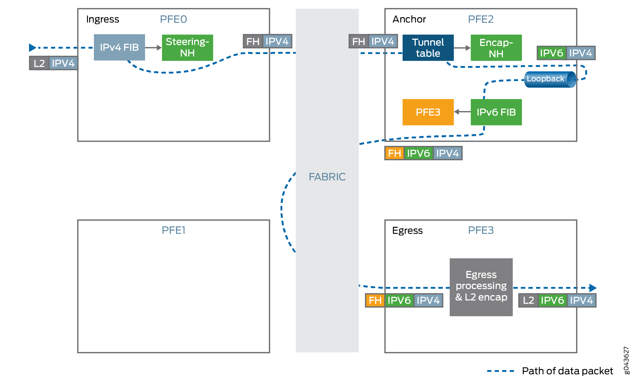
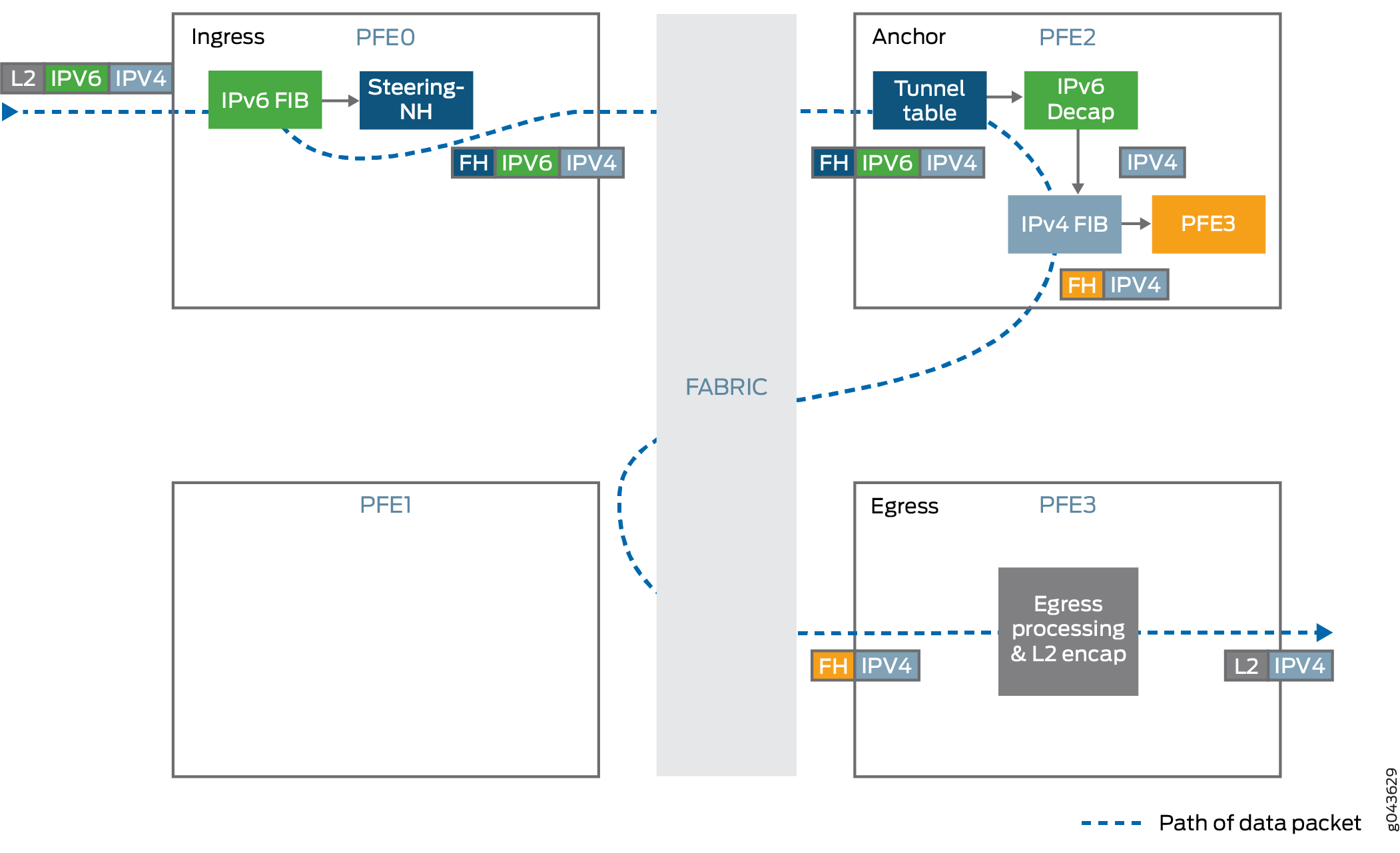
Tunnel Localization
The dynamic tunnel infrastructure is enhanced with tunnel localization to support a larger number of tunnels. There is a need for tunnel localization to provide resiliency to handle traffic when the anchor fails. One or more chassis back up one another and let the routing protocol process (rpd) steer traffic away from the failure point to the backup chassis. The chassis advertises only these aggregate prefixes instead of the individual loopback addresses into the network.
Tunnel Handling
IPv4 over IPv6 tunnels use the dynamic tunnel infrastructure along with tunnel anchoring to support the required chassis wide scale. The tunnel state is localized to a Packet Forwarding Engine and the other Packet Forwarding Engines steer the traffic to the tunnel anchor.
Tunnel Ingress
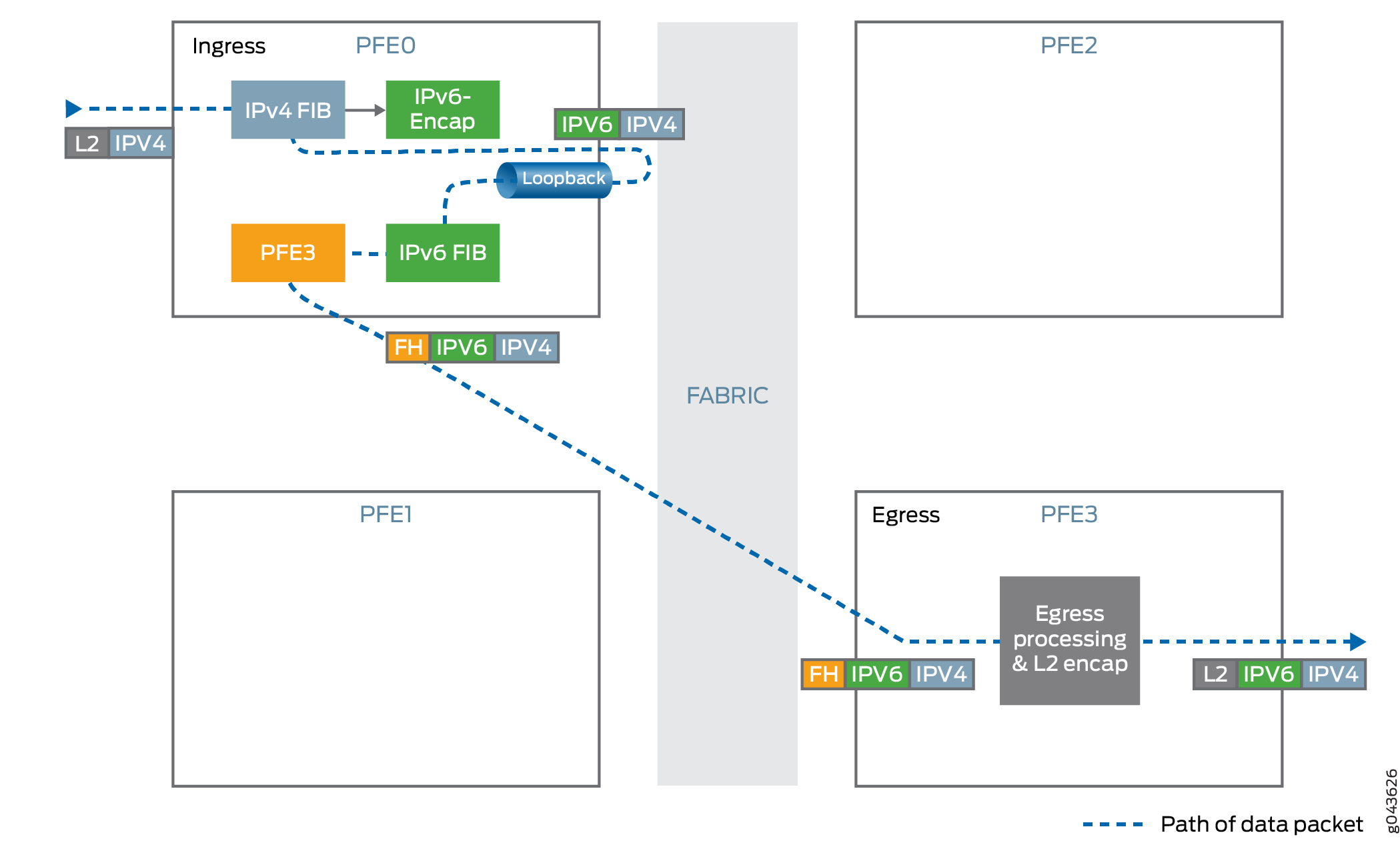
-
Encapsulates IPv4 traffic inside the IPv6 header.
Maximum transmission unit (MTU) enforcement is performed before encapsulation. If the encapsulated packet size exceeds the tunnel MTU and the IPv4 packet’s
DF-bitis not set then the packet is fragmented and these fragments are encapsulated. -
Uses hash-based traffic load balancing on inner packet headers.
-
Forwards traffic to the destination IPv6 address. The IPv6 address is taken from the IPv6 header.
Tunnel Egress
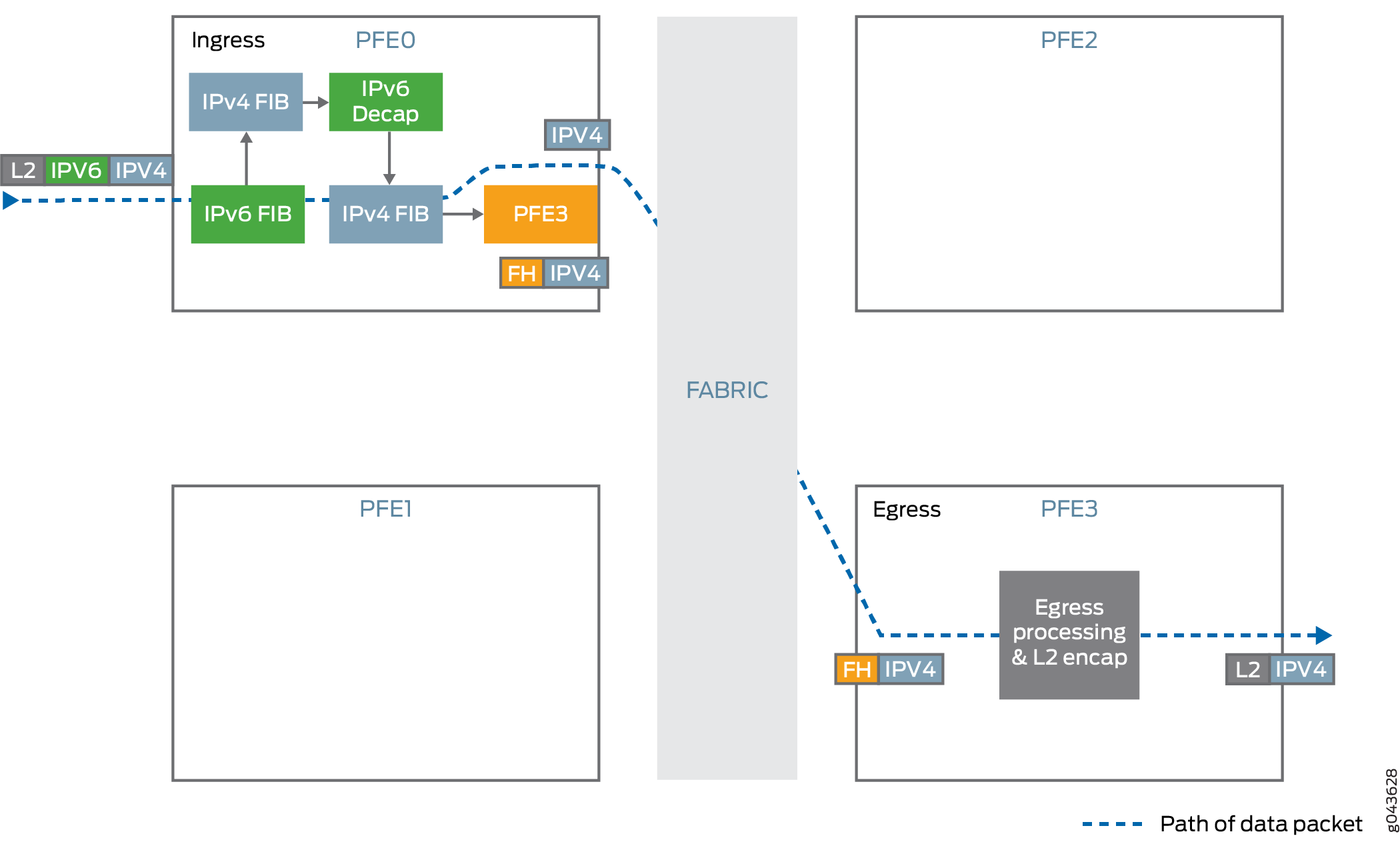
-
Decapsulates the IPv4 packet present inside the IPv6 packet.
-
Performs anti-spoof checking to ensure that the IPv6, IPv4 pair matches with the information that was used for setting up the tunnel.
-
Looks up the IPv4 destination address from the decapsulated packet’s IPv4 header and forwards the packet to the specified IPv4 address.
Tunnel Load Balancing and Anchor Packet Forwarding Engine Failure Handling
The Packet Forwarding Engine failure needs to be handled promptly to avoid null-route filtering of tunnel traffic anchored on the Packet Forwarding Engine. Tunnel localization involves the use of BGP advertisements to repair the failure globally. The tunnel traffic is diverted away from the failure point to other backup chassis that contains the identical tunnel state. For traffic load balancing, the chassis is configured to advertise different multiple exit discriminator (MED) values for each of the prefix sets so that only the traffic for one fourth of the tunnels goes through each chassis. CPE traffic is also handled in a similar manner by configuring the same set of anycast addresses on each chassis and steering only one fourth of traffic towards each chassis.
Anchor Packet Forwarding Engine is the single entity that does
all processing for a tunnel. The anchor Packet Forwarding Engine selection
is through static provisioning and tied to the Packet Forwarding Engine
physical interfaces. When one of the Packet Forwarding Engines goes
down, the daemon marks all the Packet Forwarding Engines down on the
line card and communicates this information to routing protocol process
routing protocol process and other daemons. The routing protocol process
sends out BGP withdrawals for the prefixes that are anchored on the
failed Packet Forwarding Engine and the IPv6 addresses assigned to
the Packet Forwarding Engine that is down. These advertisements reroute
traffic to other backup chassis. When the failed Packet Forwarding
Engine is up again, the chassis marks the Packet Forwarding Engine
as up and updates routing protocol process. The routing
protocol process triggers BGP updates to its peers that tunnels anchored
to the specific Packet Forwarding Engine are now available for routing
traffic. This process might take minutes for large scale tunnel configuration.
Therefore, the Ack mechanism is built into the system to
ensure minimal traffic loss while switching traffic back to the original
chassis.
Tunnel Loopback Stream Statistics
Dynamic tunnel infrastructure uses loopback streams in Packet Forwarding Engine for looping the packet after encapsulation. Since the bandwidth of this loopback stream is limited there is a need to monitor the performance of tunnel loopback streams.
To monitor the statistics of the loopback stream, use the operational
command show pfe statistics traffic detail that displays
the aggregated loopback stream statistics including forwarding rate,
drop packet rate and the byte rate.
See Also
Configuring BGP to Redistribute IPv4 Routes with IPv6 Next-Hop Addresses
Starting in Release 17.3R1, Junos OS devices can forward IPv4 traffic over an IPv6-only network, which generally cannot forward IPv4 traffic. As described in RFC 5549, IPv4 traffic is tunneled from CPE devices to IPv4-over-IPv6 gateways. These gateways are announced to CPE devices through anycast addresses. The gateway devices then create dynamic IPv4-over-IPv6 tunnels to remote customer premises equipment and advertise IPv4 aggregate routes to steer traffic. Route reflectors with programmable interfaces inject the tunnel information into the network. The route reflectors are connected through IBGP to gateway routers, which advertise the IPv4 addresses of host routes with IPv6 addresses as the next hop.
Dynamic IPv4-over-IPv6 tunnel feature does not support unified ISSU in Junos OS Release 17.3R1.
Before you begin configuring BGP to distribute IPv4 routes with IPv6 next-hop addresses, do the following:
Configure the device interfaces.
Configure OSPF or any other IGP protocol.
Configure MPLS and LDP.
Configure BGP.
To configure BGP to distribute IPv4 routes with IPv6 next-hop addresses:
See Also
Enabling Layer 2 VPN and VPLS Signaling
You can enable BGP to carry Layer 2 VPN and VPLS NLRI messages.
To enable VPN and VPLS signaling, include the family statement:
family { l2vpn { signaling { prefix-limit { maximum number; teardown <percentage> <idle-timeout (forever | minutes)>; drop-excess <percentage>; hide-excess <percentage>; } } } }
For a list of hierarchy levels at which you can include this statement, see the statement summary section for this statement.
To configure a maximum number of prefixes, include the prefix-limit statement:
prefix-limit { maximum number; teardown <percentage> <idle-timeout (forever | minutes)>; drop-excess <percentage>; hide-excess <percentage>;}
For a list of hierarchy levels at which you can include this statement, see the statement summary section for this statement.
When you set the maximum number of prefixes, a message is logged when that number is reached. If
you include the teardown statement, the session is torn down when the
maximum number of prefixes is reached. If you specify a percentage, messages are logged
when the number of prefixes reaches that percentage. Once the session is torn down, it
is reestablished in a short time. Include the idle-timeout statement to
keep the session down for a specified amount of time, or forever. If you specify
forever, the session is reestablished only after you use the
clear bgp
                    neighbor
command. If you include the drop-excess
<percentage> statement and specify a
percentage, the excess routes are dropped when the number of prefixes exceeds the
percentage. If you include the hide-excess
<percentage> statement and specify a percentage,
the excess routes are hidden when the number of prefixes exceeds the percentage. If the
percentage is modified, the routes are re-evaluated automatically.
See Also
Understanding BGP Flow Routes for Traffic Filtering
A flow route is an aggregation of match conditions for IP packets. Flow routes are
installed as Input Forwarding Table Filters (implicit) and are propagated through the
network using flow-specification network-layer reachability information (NLRI) messages
and installed into the flow routing table
instance-name.inetflow.0. Packets can travel
through flow routes only if specific match conditions are met.
Flow routes and firewall filters are similar in that they filter packets based on their components and perform an action on the packets that match. Flow routes provide traffic filtering and rate-limiting capabilities much like firewall filters. In addition, you can propagate flow routes across different autonomous systems.
Flow routes are propagated by BGP through flow-specification NLRI messages. You must enable BGP to propagate these NLRIs.
Beginning with Junos OS Release 15.1, changes are implemented to extend nonstop active routing (NSR) support for existing inet-flow and inetvpn-flow families and extend route validation for BGP flowspec per draft-ietf-idr-bgp-flowspec-oid-01. Two new statements are introduced as part of this enhancement. See enforce-first-as and no-install.
Beginning with Junos OS Release 16.1, IPv6 support is extended to BGP flow specification that allows propagation of traffic flow specification rules for IPv6 and VPN-IPv6 packets. BGP flow specification automates coordination of traffic filtering rules in order to mitigate distributed denial-of-service attack during nonstop active routing (NSR).
Starting with Junos OS Release 16.1R1, BGP flow specification supports traffic-marking
extended-community filtering action. For IPv4 traffic, Junos OS
modifies the DiffServ code point (DSCP) bits of a transiting IPv4 packet to the
corresponding value of the extended community. For IPv6 packets, Junos OS modifies the
first six bits of the traffic class field of the transmitting IPv6
packet to the corresponding value of the extended community.
Starting in Junos OS Release 17.1R1, BGP can carry flow-specification network layer reachability information (NLRI) messages on PTX Series routers that have third-generation FPCs (FPC3-PTX-U2 and FPC3-PTX-U3 on PTX5000 and FPC3-SFF-PTX-U0 and FPC3-SFF-PTX-U1 on PTX3000) installed. Propagating firewall filter information as part of BGP enables you to propagate firewall filters against denial-of-service (DOS) attacks dynamically across autonomous systems.
Starting in Junos OS Release 17.2R1, BGP can carry flow-specification network layer reachability information (NLRI) messages on PTX1000 routers that have third-generation FPCs installed. Propagating firewall filter information as part of BGP enables you to propagate firewall filters against denial-of-service (DOS) attacks dynamically across autonomous systems.
Starting in cRPD Release 20.3R1, flow routes and policing rules propagated through BGP flow specification NLRI are downloaded to Linux kernel through Linux Netfilter framework on cRPD environments.
- Match Conditions for Flow Routes
- Actions for Flow Routes
- Validating Flow Routes
- Support for BGP Flow-Specification Algorithm Version 7 and Later
Match Conditions for Flow Routes
You specify conditions that the packet must match before the action in the
then statement is taken for a flow route. All conditions in the
from statement must match for the action to be taken. The order
in which you specify match conditions is not important, because a packet must match
all the conditions in a term for a match to occur.
To configure a match condition, include the match statement at the
[edit routing-options flow] hierarchy level.
Table 1 describes the flow route match conditions.
|
Match Condition |
Description |
|---|---|
|
|
IP destination address field. You can use the |
|
|
TCP or User Datagram Protocol (UDP) destination port field. You
cannot specify both the In place of the numeric value, you can specify one of the
following text synonyms (the port numbers are also listed):
|
|
|
Differentiated Services code point (DSCP). The DiffServ protocol uses the type-of-service (ToS) byte in the IP header. The most significant six bits of this byte form the DSCP. You can specify DSCP in hexadecimal or decimal form. |
|
|
Match the flow label value. The value of this field ranges from 0 through 1048575. This match condition is supported only on Junos devices with
enhanced MPCs that are configured for
|
|
|
Fragment type field. The keywords are grouped by the fragment type with which they are associated:
This match condition is supported only on Junos OS devices with
enhanced MPCs that are configured for
|
|
|
ICMP code field. This value or keyword provides more specific
information than In place of the numeric value, you can specify one of the following text synonyms (the field values are also listed). The keywords are grouped by the ICMP type with which they are associated:
|
|
|
ICMP packet type field. Normally, you specify this match in
conjunction with the In place of the numeric value, you can specify one of the
following text synonyms (the field values are also listed):
|
|
|
Total IP packet length. |
|
|
TCP or UDP source or destination port field. You cannot specify
both the In place of the numeric value, you can specify one of the text
synonyms listed under |
|
|
IP protocol field. In place of the numeric value, you can specify
one of the following text synonyms (the field values are also
listed): This match condition is supported for IPv6 only on Junos devices
with enhanced MPCs that are configured for
|
|
|
IP source address field. You can use the |
|
|
TCP or UDP source port field. You cannot specify the
In place of the numeric field, you can specify one of the text
synonyms listed under |
|
|
TCP header format. |
Actions for Flow Routes
You can specify the action to take if the packet matches the conditions you have
configured in the flow route. To configure an action, include the
then statement at the [edit routing-options
flow] hierarchy level.
Table 2 describes the flow route actions.
|
Action or Action Modifier |
Description |
|---|---|
| Actions | |
|
|
Accept a packet. This is the default. |
|
|
Discard a packet silently, without sending an Internet Control Message Protocol (ICMP) message. |
|
|
Replace any communities in the route with the specified communities. |
|
mark value |
Set a DSCP value for traffic that matches this flow. Specify a
value from 0 through 63. This action is supported only on Junos
devices with enhanced MPCs that are configured for
|
|
|
Continue to the next match condition for evaluation. |
|
|
Specify a routing instance to which packets are forwarded. |
|
|
Limit the bandwidth on the flow route. Express the limit in bits per second (bps). Beginning with Junos OS Release 16.1R4, the rate-limit range is [0 through 1000000000000]. |
|
|
Sample the traffic on the flow route. |
Validating Flow Routes
The Junos OS installs flow routes into the flow routing table only if they have been validated using the validation procedure. The Routing Engine does the validation before the installing routes into the flow routing table.
Flow routes received using the BGP network layer reachability information (NLRI)
messages are validated before they are installed into the flow primary instance
routing table instance.inetflow.0. The validation procedure is
described in the draft-ietf-idr-flow-spec-09.txt, Dissemination of Flow
Specification Rules. You can bypass the validation process for flow
routes using BGP NLRI messages and use your own specific import policy.
To trace validation operations, include the validation statement at
the [edit routing-options flow] hierarchy level.
Support for BGP Flow-Specification Algorithm Version 7 and Later
By default, the Junos OS uses the term-ordering algorithm defined in version 6 of the BGP flow specification draft. In Junos OS Release 10.0 and later, you can configure the router to comply with the term-ordering algorithm first defined in version 7 of the BGP flow specification and supported through RFC 5575, Dissemination of Flow Specification Routes.
We recommend that you configure the Junos OS to use the term-ordering algorithm first defined in version 7 of the BGP flow specification draft. We also recommend that you configure the Junos OS to use the same term-ordering algorithm on all routing instances configured on a router.
To configure BGP to use the flow-specification algorithm first defined in version 7
of the Internet draft, include the standard statement at the
[edit routing-options flow term-order] hierarchy level.
To revert to using the term-ordering algorithm defined in version 6, include the
legacy statement at the [edit routing-options flow
term-order] hierarchy level.
The configured term order has only local significance. That is, the term order
does not propagate with flow routes sent to the remote BGP peers, whose term
order is completely determined by their own term order configuration. Therefore,
you should be careful when configuring the order-dependent action next
term when you are not aware of the term order configuration of the
remote peers. The local next term might differ from the
next term configured on the remote peer.
On Junos OS Evolved, next term cannot appear as the last term of
the action. A filter term where next term is specified as an
action but without any match conditions configured is not supported.
Starting in Junos OS Release 16.1, you have the option to not apply the flowspec filter to traffic received on specific interfaces. A new term is added at the beginning of the flowspec filter that accepts any packet received on these specific interfaces. The new term is a variable that creates an exclusion list of terms attached to the forwarding table filter as a part of the flow specification filter.
To exclude the flowspec filter from being applied to traffic
received on specific interfaces, you must first configure a
group-id on such interfaces by including the family
inet filter group group-id statement at the
[edit interfaces] hierarchy level and then attach the
flowspec filter with the interface group by including the
flow interface-group group-id exclude statement at the
[edit routing-options] hierarchy level. You can configure only
one group-id per routing instance with the set
routing-options flow interface-group group-id statement.
See Also
Example: Enabling BGP to Carry Flow-Specification Routes
This example shows how to allow BGP to carry flow-specification network layer reachability information (NLRI) messages.
Requirements
Before you begin:
Configure the device interfaces.
Configure an interior gateway protocol (IGP).
Configure BGP.
Configure a routing policy that exports routes (such as direct routes or IGP routes) from the routing table into BGP.
Overview
Propagating firewall filter information as part of BGP enables you to propagate firewall filters against denial-of-service (DOS) attacks dynamically across autonomous systems. Flow routes are encapsulated into the flow-specification NLRI and propagated through a network or virtual private networks (VPNs), sharing filter-like information. Flow routes are an aggregation of match conditions and resulting actions for packets. They provide you with traffic filtering and rate-limiting capabilities much like firewall filters. Unicast flow routes are supported for the default instance, VPN routing and forwarding (VRF) instances, and virtual-router instances.
Import and export policies can be applied to the family inet flow or family inet-vpn flow NLRI, affecting
the flow routes accepted or advertised, similar to the way import
and export policies are applied to other BGP families. The only difference
is that the flow policy configuration must include the from rib
inetflow.0 statement. This statement causes the policy to be
applied to the flow routes. An exception to this rule occurs if the
policy has only the then reject or the then accept statement and no from statement. Then, the policy affects
all routes, including IP unicast and IP flow.
The flow route filters are first configured on a router statically,
with a set of matching criteria followed by the actions to be taken.
Then, in addition to family inet unicast, family inet
flow (or family inet-vpn flow) is configured between
this BGP-enabled device and its peers.
By default, statically configured flow routes (firewall filters)
are advertised to other BGP-enabled devices that support the family inet flow or family inet-vpn flow NLRI.
The receiving BGP-enabled device performs a validation process
before installing the firewall filter into the flow routing table instance-name.inetflow.0. The validation
procedure is described in RFC 5575, Dissemination of Flow
Specification Rules.
The receiving BGP-enabled device accepts a flow route if it passes the following criteria:
The originator of a flow route matches the originator of the best match unicast route for the destination address that is embedded in the route.
There are no more specific unicast routes, when compared to the destination address of the flow route, for which the active route has been received from a different next-hop autonomous system.
The first criterion ensures that the filter is being advertised by the next-hop used by unicast forwarding for the destination address embedded in the flow route. For example, if a flow route is given as 10.1.1.1, proto=6, port=80, the receiving BGP-enabled device selects the more specific unicast route in the unicast routing table that matches the destination prefix 10.1.1.1/32. On a unicast routing table containing 10.1/16 and 10.1.1/24, the latter is chosen as the unicast route to compare against. Only the active unicast route entry is considered. This follows the concept that a flow route is valid if advertised by the originator of the best unicast route.
The second criterion addresses situations in which a given address block is allocated to different entities. Flows that resolve to a best-match unicast route that is an aggregate route are only accepted if they do not cover more specific routes that are being routed to different next-hop autonomous systems.
You can bypass the validation process for flow routes using
BGP NLRI messages and use your own specific import policy. When BGP
is carrying flow-specification NLRI messages, the no-validate statement at the [edit protocols bgp group group-name family inet flow] hierarchy level omits the flow route validation
procedure after packets are accepted by a policy. You can configure
the import policy to match on destination address and path attributes
such as community, next-hop, and AS path. You can specify the action
to take if the packet matches the conditions you have configured in
the flow route. To configure an action, include the statement at the [edit routing-options flow] hierarchy level. The flow specification
NLRI type includes components such as destination prefix, source prefix,
protocol, and ports as defined in the RFC 5575. The import policy
can filter an inbound route using path attributes and destination
address in the flow specification NLRI. The import policy cannot filter
any other components in the RFC 5575.
The flow specification defines required protocol extensions to address most common applications of IPv4 unicast and VPN unicast filtering. The same mechanism can be reused and new match criteria added to address similar filtering for other BGP address families (for example, IPv6 unicast).
After a flow route is installed in the inetflow.0 table, it is also added to the list of firewall filters in the kernel.
On routers only, flow-specification NLRI messages are supported
in VPNs. The VPN compares the route target extended community in the
NLRI to the import policy. If there is a match, the VPN can start
using the flow routes to filter and rate-limit packet traffic. Received
flow routes are installed into the flow routing table instance-name.inetflow.0. Flow routes can also be
propagated throughout a VPN network and shared among VPNs. To enable
multiprotocol BGP (MP-BGP) to carry flow-specification NLRI for the inet-vpn address family, include the flow statement
at the [edit protocols bgp group group-name family inet-vpn] hierarchy level. VPN flow routes are supported
for the default instance only. Flow routes configured for VPNs with
family inet-vpn are not automatically validated, so the no-validate statement is not supported at the [edit protocols
bgp group group-name family inet-vpn] hierarchy
level. No validation is needed if the flow routes are configured locally
between devices in a single AS.
Import and export policies can be applied to the family
inet flow or family inet-vpn flow NLRI, affecting
the flow routes accepted or advertised, similar to the way import
and export policies are applied to other BGP families. The only difference
is that the flow policy configuration must include the from rib
inetflow.0 statement. This statement causes the policy to be
applied to the flow routes. An exception to this rule occurs if the
policy has only the then reject or the then accept statement and no from statement. Then, the policy affects
all routes, including IP unicast and IP flow.
This example shows how to configure the following export policies:
A policy that allows the advertisement of flow routes specified by a route-filter. Only the flow routes covered by the 10.13/16 block are advertised. This policy does not affect unicast routes.
A policy that allows all unicast and flow routes to be advertised to the neighbor.
A policy that disallows all routes (unicast or flow) to be advertised to the neighbor.
Topology
Configuration
- Configuring a Static Flow Route
- Advertising Flow Routes Specified by a Route Filter
- Advertising All Unicast and Flow Routes
- Advertising No Unicast or Flow Routes
- Limiting the Number of Flow Routes Installed in a Routing Table
- Limiting the Number of Prefixes Received on a BGP Peering Session
Configuring a Static Flow Route
CLI Quick Configuration
To quickly configure this example, copy the
following commands, paste them into a text file, remove any line breaks,
change any details necessary to match your network configuration,
and then copy and paste the commands into the CLI at the [edit] hierarchy level.
set routing-options flow route block-10.131.1.1 match destination 10.131.1.1/32 set routing-options flow route block-10.131.1.1 match protocol icmp set routing-options flow route block-10.131.1.1 match icmp-type echo-request set routing-options flow route block-10.131.1.1 then discard set routing-options flow term-order standard
Step-by-Step Procedure
The following example requires that you navigate various levels in the configuration hierarchy. For information about navigating the CLI, see Using the CLI Editor in Configuration Mode in the Junos OS CLI User Guide.
To configure the BGP peer sessions:
Configure the match conditions.
[edit routing-options flow route block-10.131.1.1] user@host# set match destination 10.131.1.1/32 user@host# set match protocol icmp user@host# set match icmp-type echo-request
Configure the action.
[edit routing-options flow route block-10.131.1.1] user@host# set then discard
(Recommended) For the flow specification algorithm, configure the standard-based term order.
[edit routing-options flow] user@host# set term-order standard
In the default term ordering algorithm, as specified in the flowspec RFC draft Version 6, a term with less specific matching conditions is always evaluated before a term with more specific matching conditions. This causes the term with more specific matching conditions to never be evaluated. Version 7 of RFC 5575 made a revision to the algorithm so that the more specific matching conditions are evaluated before the less specific matching conditions. For backward compatibility, the default behavior is not altered in Junos OS, even though the newer algorithm makes more sense. To use the newer algorithm, include the
term-order standardstatement in the configuration. This statement is supported in Junos OS Release 10.0 and later.
Results
From configuration mode, confirm your configuration
by entering the show routing-options command. If the output
does not display the intended configuration, repeat the instructions
in this example to correct the configuration.
[edit]
user@host# show routing-options
flow {
term-order standard;
route block-10.131.1.1 {
match {
destination 10.131.1.1/32;
protocol icmp;
icmp-type echo-request;
}
then discard;
}
}
If you are done configuring the device, enter commit from configuration mode.
Advertising Flow Routes Specified by a Route Filter
CLI Quick Configuration
To quickly configure this example, copy the
following commands, paste them into a text file, remove any line breaks,
change any details necessary to match your network configuration,
and then copy and paste the commands into the CLI at the [edit] hierarchy level.
set protocols bgp group core family inet unicast set protocols bgp group core family inet flow set protocols bgp group core export p1 set protocols bgp group core peer-as 65000 set protocols bgp group core neighbor 10.12.99.5 set policy-options policy-statement p1 term a from rib inetflow.0 set policy-options policy-statement p1 term a from route-filter 10.13.0.0/16 orlonger set policy-options policy-statement p1 term a then accept set policy-options policy-statement p1 term b then reject set routing-options autonomous-system 65001
Step-by-Step Procedure
The following example requires that you navigate various levels in the configuration hierarchy. For information about navigating the CLI, see Using the CLI Editor in Configuration Mode in the Junos OS CLI User Guide.
To configure the BGP peer sessions:
Configure the BGP group.
[edit protocols bgp group core] user@host# set family inet unicast user@host# set family inet flow user@host# set export p1 user@host# set peer-as 65000 user@host# set neighbor 10.12.99.5
Configure the flow policy.
[edit policy-options policy-statement p1] user@host# set term a from rib inetflow.0 user@host# set term a from route-filter 10.13.0.0/16 orlonger user@host# set term a then accept user@host# set term b then reject
Configure the local autonomous system (AS) number.
[edit routing-options] user@host# set autonomous-system 65001
Results
From configuration mode, confirm your configuration
by entering the show protocols, show policy-options, and show routing-options commands. If the output does
not display the intended configuration, repeat the instructions in
this example to correct the configuration.
[edit]
user@host# show protocols
bgp {
group core {
family inet {
unicast;
flow;
}
export p1;
peer-as 65000;
neighbor 10.12.99.5;
}
}
[edit]
user@host# show policy-options
policy-statement p1 {
term a {
from {
rib inetflow.0;
route-filter 10.13.0.0/16 orlonger;
}
then accept;
}
term b {
then reject;
}
}
[edit] user@host# show routing-options autonomous-system 65001;
If you are done configuring the device, enter commit from configuration mode.
Advertising All Unicast and Flow Routes
CLI Quick Configuration
To quickly configure this example, copy the
following commands, paste them into a text file, remove any line breaks,
change any details necessary to match your network configuration,
and then copy and paste the commands into the CLI at the [edit] hierarchy level.
set protocols bgp group core family inet unicast set protocols bgp group core family inet flow set protocols bgp group core export p1 set protocols bgp group core peer-as 65000 set protocols bgp group core neighbor 10.12.99.5 set policy-options policy-statement p1 term a then accept set routing-options autonomous-system 65001
Step-by-Step Procedure
The following example requires that you navigate various levels in the configuration hierarchy. For information about navigating the CLI, see Using the CLI Editor in Configuration Mode in the Junos OS CLI User Guide.
To configure the BGP peer sessions:
Configure the BGP group.
[edit protocols bgp group core] user@host# set family inet unicast user@host# set family inet flow user@host# set export p1 user@host# set peer-as 65000 user@host# set neighbor 10.12.99.5
Configure the flow policy.
[edit policy-options policy-statement p1] user@host# set term a then accept
Configure the local autonomous system (AS) number.
[edit routing-options] user@host# set autonomous-system 65001
Results
From configuration mode, confirm your configuration
by entering the show protocols, show policy-options, and show routing-options commands. If the output does
not display the intended configuration, repeat the instructions in
this example to correct the configuration.
[edit]
user@host# show protocols
bgp {
group core {
family inet {
unicast;
flow;
}
export p1;
peer-as 65000;
neighbor 10.12.99.5;
}
}
[edit]
user@host# show policy-options
policy-statement p1 {
term a {
prefix-list inetflow;
}
then accept;
}
}
[edit] user@host# show routing-options autonomous-system 65001;
If you are done configuring the device, enter commit from configuration mode.
Advertising No Unicast or Flow Routes
CLI Quick Configuration
To quickly configure this example, copy the
following commands, paste them into a text file, remove any line breaks,
change any details necessary to match your network configuration,
and then copy and paste the commands into the CLI at the [edit] hierarchy level.
set protocols bgp group core family inet unicast set protocols bgp group core family inet flow set protocols bgp group core export p1 set protocols bgp group core peer-as 65000 set protocols bgp group core neighbor 10.12.99.5 set policy-options policy-statement p1 term a then reject set routing-options autonomous-system 65001
Step-by-Step Procedure
The following example requires that you navigate various levels in the configuration hierarchy. For information about navigating the CLI, see Using the CLI Editor in Configuration Mode in the Junos OS CLI User Guide.
To configure the BGP peer sessions:
Configure the BGP group.
[edit protocols bgp group core] user@host# set family inet unicast user@host# set family inet flow user@host# set export p1 user@host# set peer-as 65000 user@host# set neighbor 10.12.99.5
Configure the flow policy.
[edit policy-options policy-statement p1] user@host# set term a then reject
Configure the local autonomous system (AS) number.
[edit routing-options] user@host# set autonomous-system 65001
Results
From configuration mode, confirm your configuration
by entering the show protocols, show policy-options, and show routing-options commands. If the output does
not display the intended configuration, repeat the instructions in
this example to correct the configuration.
[edit]
user@host# show protocols
bgp {
group core {
family inet {
unicast;
flow;
}
export p1;
peer-as 65000;
neighbor 10.12.99.5;
}
}
[edit]
user@host# show policy-options
policy-statement p1 {
term a {
then reject;
}
}
[edit] user@host# show routing-options autonomous-system 65001;
If you are done configuring the device, enter commit from configuration mode.
Limiting the Number of Flow Routes Installed in a Routing Table
CLI Quick Configuration
To quickly configure this example, copy the
following commands, paste them into a text file, remove any line breaks,
change any details necessary to match your network configuration,
and then copy and paste the commands into the CLI at the [edit] hierarchy level.
set routing-options rib inetflow.0 maximum-prefixes 1000 set routing-options rib inetflow.0 maximum-prefixes threshold 50
Step-by-Step Procedure
The following example requires that you navigate various levels in the configuration hierarchy. For information about navigating the CLI, see Using the CLI Editor in Configuration Mode in the Junos OS CLI User Guide.
Application of a route limit might result in unpredictable dynamic route protocol behavior. For example, once the limit is reached and routes are being rejected, BGP does not necessarily attempt to reinstall the rejected routes after the number of routes drops below the limit. BGP sessions might need to be cleared to resolve this issue.
To limit the flow routes:
Set an upper limit for the number of prefixes installed in
inetflow.0table.[edit routing-options rib inetflow.0] user@host# set maximum-prefixes 1000
Set a threshold value of 50 percent, where when 500 routes are installed, a warning is logged in the system log.
[edit routing-options rib inetflow.0] user@host# set maximum-prefixes threshold 50
Results
From configuration mode, confirm your configuration
by entering the show routing-options command. If the output
does not display the intended configuration, repeat the instructions
in this example to correct the configuration.
[edit]
user@host# show routing-options
rib inetflow.0 {
maximum-prefixes 1000 threshold 50;
}
If you are done configuring the device, enter commit from configuration mode.
Limiting the Number of Prefixes Received on a BGP Peering Session
CLI Quick Configuration
To quickly configure this example, copy the
following commands, paste them into a text file, remove any line breaks,
change any details necessary to match your network configuration,
and then copy and paste the commands into the CLI at the [edit] hierarchy level.
set protocols bgp group x1 neighbor 10.12.99.2 family inet flow prefix-limit maximum 1000 set protocols bgp group x1 neighbor 10.12.99.2 family inet flow prefix-limit teardown 50 set protocols bgp group x1 neighbor 10.12.99.2 family inet flow prefix-limit drop-excess 50 set protocols bgp group x1 neighbor 10.12.99.2 family inet flow prefix-limit hide-excess 50
You can include either the teardown <percentage>,
drop-excess <percentage>, or
hide-excess<percentage> statement option one at a
time.
Step-by-Step Procedure
The following example requires that you navigate various levels in the configuration hierarchy. For information about navigating the CLI, see Using the CLI Editor in Configuration Mode in the Junos OS CLI User Guide.
Configuring a prefix limit for a specific neighbor provides more predictable control over which peer can advertise how many flow routes.
To limit the number of prefixes:
Set a limit of 1000 BGP routes from neighbor 10.12.99.2.
[edit protocols bgp group x1] user@host# set neighbor 10.12.99.2 family inet flow prefix-limit maximum 1000
-
Configure the neighbor session or prefixes to perform either
teardown <percentage>,drop-excess <percentage>, orhide-excess<percentage>statement option when the session or prefixes reaches its limit.[edit routing-options rib inetflow.0] user@host# set neighbor 10.12.99.2 family inet flow prefix-limit teardown 50 set neighbor 10.12.99.2 family inet flow prefix-limit drop-excess 50 set neighbor 10.12.99.2 family inet flow prefix-limit hide-excess 50
If you specify the
teardown <percentage>statement and specify a percentage, messages are logged when the number of prefixes reaches that percentage. After the session is brought down, the session reestablishes in a short time unless you include theidle-timeoutstatement.If you specify the
drop-excess <percentage>statement and specify a percentage, the excess routes are dropped when the number of prefixes exceeds that percentageIf you specify the
hide-excess <percentage>statement and specify a percentage, the excess routes are hidden when the number of prefixes exceeds that percentage.
Results
From configuration mode, confirm your configuration
by entering the show protocols command. If the output does
not display the intended configuration, repeat the instructions in
this example to correct the configuration.
[edit]
user@host# show protocols
bgp {
group x1 {
neighbor 10.12.99.2 {
flow {
prefix-limit {
maximum 1000;
teardown 50;
drop-excess <percentage>;
hide-excess <percentage>;
}
}
}
}
}
}
If you are done configuring the device, enter commit from configuration mode.
Verification
Confirm that the configuration is working properly.
- Verifying the NLRI
- Verifying Routes
- Verifying Flow Validation
- Verifying Firewall Filters
- Verifying System Logging When Exceeding the Number of Allowed Flow Routes
- Verifying System Logging When Exceeding the Number of Prefixes Received on a BGP Peering Session
Verifying the NLRI
Purpose
Look at the NLRI enabled for the neighbor.
Action
From operational mode, run the show bgp neighbor
10.12.99.5 command. Look for inet-flow in the output.
user@host> show bgp neighbor 10.12.99.5
Peer: 10.12.99.5+3792 AS 65000 Local: 10.12.99.6+179 AS 65002
Type: External State: Established Flags: <Sync>
Last State: OpenConfirm Last Event: RecvKeepAlive
Last Error: None
Export: [ direct ]
Options: <Preference HoldTime AddressFamily PeerAS Refresh>
Address families configured: inet-unicast inet-multicast inet-flow
Holdtime: 90 Preference: 170
Number of flaps: 1
Error: 'Cease' Sent: 0 Recv: 1
Peer ID: 10.255.71.161 Local ID: 10.255.124.107 Active Holdtime: 90
Keepalive Interval: 30 Peer index: 0
Local Interface: e1-3/0/0.0
NLRI advertised by peer: inet-unicast inet-multicast inet-flow
NLRI for this session: inet-unicast inet-multicast inet-flow
Peer supports Refresh capability (2)
Table inet.0 Bit: 10000
RIB State: BGP restart is complete
Send state: in sync
Active prefixes: 2
Received prefixes: 2
Suppressed due to damping: 0
Advertised prefixes: 3
Table inet.2 Bit: 20000
RIB State: BGP restart is complete
Send state: in sync
Active prefixes: 0
Received prefixes: 0
Suppressed due to damping: 0
Advertised prefixes: 0
Table inetflow.0 Bit: 30000
RIB State: BGP restart is complete
Send state: in sync
Active prefixes: 0
Received prefixes: 0
Suppressed due to damping: 0
Advertised prefixes: 0
Last traffic (seconds): Received 29 Sent 15 Checked 15
Input messages: Total 5549 Updates 2618 Refreshes 0 Octets 416486
Output messages: Total 2943 Updates 1 Refreshes 0 Octets 55995
Output Queue[0]: 0
Output Queue[1]: 0
Output Queue[2]: 0
Verifying Routes
Purpose
Look at the flow routes. The sample output shows a flow route learned from BGP and a statically configured flow route.
For locally configured flow routes (configured at the [edit
routing-options flow] hierarchy level), the routes are installed
by the flow protocol. Therefore, you can display the flow routes by
specifying the table, as in show route table inetflow.0 or show route table instance-name.inetflow.0, where instance-name is the routing
instance name. Or, you can display all locally configured flow routes
across multiple routing instances by running the show route protocol
flow command.
If a flow route is not locally configured, but received from
the router’s BGP peer, this flow route is installed in the routing
table by BGP. You can display the flow routes by specifying the table
or by running show route protocol bgp, which displays all
BGP routes (flow and non-flow).
Action
From operational mode, run the show route table
inetflow.0 command.
user@host> show route table inetflow.0
inetflow.0: 2 destinations, 2 routes (2 active, 0 holddown, 0 hidden)
+ = Active Route, - = Last Active, * = Both

100.100.100.100,*,proto=1,icmp-type=8/term:1
                   *[BGP/170] 00:00:18, localpref 100, from 100.0.12.2
                      AS path: 2000 I, validation-state: unverified
                      Fictitious
200.200.200.200,*,proto=6,port=80/term:2
                   *[BGP/170] 00:00:18, localpref 100, from 100.0.12.2
                      AS path: 2000 I, validation-state: unverified
                      Fictitious
user@host> show route table inetflow.0 extensive
inetflow.0: 3 destinations, 3 routes (3 active, 0 holddown, 0 hidden)
7.7.7.7,8.8.8.8/term:1 (1 entry, 1 announced)
TSI:
KRT in dfwd;
Action(s): accept,count
        *Flow   Preference: 5
                Next hop type: Fictitious
                Address: 0x8d383a4
                Next-hop reference count: 3
                State: <Active>
                Local AS: 65000
                Age: 9:50
                Task: RT Flow
                Announcement bits (1): 0-Flow
                AS path: I
user@host> show route hidden
inetflow.0: 2 destinations, 2 routes (0 active, 0 holddown, 2 hidden)
+ = Active Route, - = Last Active, * = Both

100.100.100.100,*,proto=1,icmp-type=8/term:N/A
                    [BGP ] 00:00:17, localpref 100, from 100.0.12.2
                      AS path: 2000 I, validation-state: unverified
                      Fictitious
200.200.200.200,*,proto=6,port=80/term:N/A
                    [BGP ] 00:00:17, localpref 100, from 100.0.12.2
                      AS path: 2000 I, validation-state: unverified
                      Fictitious
Meaning
A flow route represents a term of a firewall filter.
When you configure a flow route, you specify the match conditions
and the actions. In the match attributes, you can match a source address,
a destination address, and other qualifiers such as the port and the
protocol. For a single flow route that contains multiple match conditions,
all the match conditions are encapsulated in the prefix field of the
route. When you issue the show route command on a flow
route, the prefix field of the route is displayed with all of the
match conditions. 10.12.44.1,* means that the matching
condition is match destination 10.12.44.1/32. If the prefix
in the output were *,10.12.44.1, this would mean that the
match condition was match source 10.12.44.1/32. If the
matching conditions contain both a source and a destination, the asterisk
is replaced with the address.
The term-order numbers indicate the sequence of the terms (flow
routes) being evaluated in the firewall filter. The show route
extensive command displays the actions for each term (route).
Verifying Flow Validation
Purpose
Display flow route information.
Action
From operational mode, run the show route flow validation detail command.
user@host> show route flow validation detail
inet.0:
0.0.0.0/0
                Internal node: best match, inconsistent
10.0.0.0/8
                Internal node: no match, inconsistent
10.12.42.0/24
                Internal node: no match, consistent, next-as: 65003
                Active unicast route
                    Dependent flow destinations: 1
                    Origin: 10.255.124.106, Neighbor AS: 65003
10.12.42.1/32
                Flow destination (1 entries, 1 match origin)
                    Unicast best match: 10.12.42.0/24
                    Flags: Consistent
10.131.0.0/16
                Internal node: no match, consistent, next-as: 65001
                Active unicast route
                    Dependent flow destinations: 5000
                    Origin: 10.12.99.2, Neighbor AS: 65001
10.131.0.0/19
                Internal node: best match
10.131.0.0/20
                Internal node: best match
10.131.0.0/21
Verifying Firewall Filters
Purpose
Display the firewall filters that are installed in the kernel.
Action
From operational mode, run the show firewall command.
user@host> show firewall
Filter: __default_bpdu_filter__
Filter: __flowspec_default_inet__
Counters:
Name                                                Bytes              Packets
10.12.42.1,*                                            0                    0
196.1.28/23,*                                           0                    0
196.1.30/24,*                                           0                    0
196.1.31/24,*                                           0                    0
196.1.32/24,*                                           0                    0
196.1.56/21,*                                           0                    0
196.1.68/24,*                                           0                    0
196.1.69/24,*                                           0                    0
196.1.70/24,*                                           0                    0
196.1.75/24,*                                           0                    0
196.1.76/24,*                                           0                    0
Verifying System Logging When Exceeding the Number of Allowed Flow Routes
Purpose
If you configure a limit on the number of flow routes installed, as described in Limiting the Number of Flow Routes Installed in a Routing Table, view the system log message when the threshold is reached.
Action
From operational mode, run the show log <message> command.
user@host> show log message
Jul 12 08:19:01  host rpd[2748]: RPD_RT_MAXROUTES_WARN: Number of routes (1000) in
table inetflow.0 exceeded warning threshold (50 percent of configured maximum 1000)
Verifying System Logging When Exceeding the Number of Prefixes Received on a BGP Peering Session
Purpose
If you configure a limit on the number of flow routes installed, as described in Limiting the Number of Prefixes Received on a BGP Peering Session, view the system log message when the threshold is reached.
Action
From operational mode, run the show log message command.
If you specify the teradown <percentage> statement
option:
user@host> show log message
Jul 12 08:44:47  host rpd[2748]: 10.12.99.2 (External AS 65001): Shutting down peer due to
exceeding configured maximum  prefix-limit(1000) for inet-flow nlri: 1001
If you specify the drop-excess <percentage> statement
option:
user@host> show log message
Jul 27 15:26:57  R1_re rpd[32443]: BGP_DROP_PREFIX_LIMIT_EXCEEDED: 1.1.1.2 (Internal
AS 1): Exceeded drop-excess maximum prefix-limit(4) for inet-unicast nlri: 5 (instance master)
If you specify the hide-excess <percentage> statement
option:
user@host> show log message
Jul 27 15:26:57  R1_re rpd[32443]: BGP_HIDE_PREFIX_LIMIT_EXCEEDED: 1.1.1.2 (Internal
AS 1): Exceeded hide-excess maximum prefix-limit(4) for inet-unicast nlri: 5 (instance master)
Example: Configuring BGP to Carry IPv6 Flow Specification Routes
This example shows how to configure IPv6 flow specification for traffic filtering. BGP flow specification can be used to automate inter-domain and intra-domain coordination of traffic filtering rules in order to mitigate denial-of-service attacks.
Requirements
This example uses the following hardware and software components:
-
Two MX Series routers
-
Junos OS Release 16.1 or later
Before you enable BGP to carry IPv6 flow specification routes:
-
Configure IP addresses on the device interfaces.
-
Configure BGP.
-
Configure a routing policy that exports routes (such as static routes, direct routes, or IGP routes) from the routing table into BGP.
Overview
Flow specification provides protection against denial-of-service attacks and restricts bad traffic that consumes the bandwidth and stops it near the source. In earlier Junos OS releases, flow specification rules were propagated for IPv4 over BGP as network layer reachability information. Beginning with Junos OS Release 16.1, the flow specification feature is supported on the IPv6 family and allows propagation of traffic flow specification rules for IPv6 and IPv6 VPN.
Topology
Figure 7 shows the sample topology. Router R1 and Router R2 belong to different autonomous systems. IPv6 flow specification is configured on Router R2. All incoming traffic is filtered based on the flow specification conditions, and the traffic is treated differently depending on the specified action. In this example, all traffic heading to abcd::11:11:11:10/128 that matches the flow specification conditions is discarded; whereas, traffic destined to abcd::11:11:11:30/128 and matching the flow specification conditions is accepted.
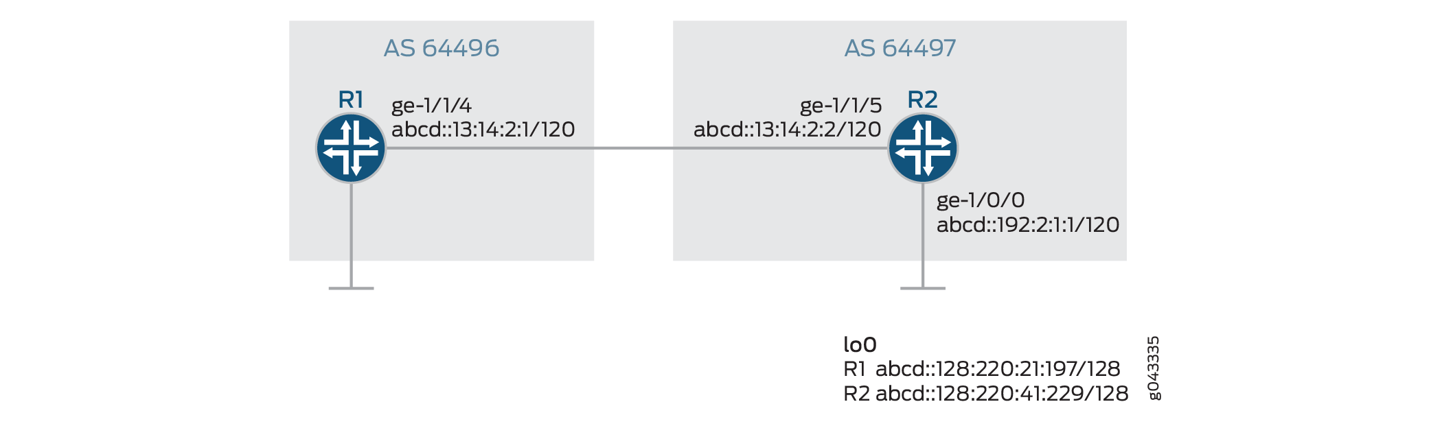
Configuration
CLI Quick Configuration
To quickly configure this example, copy the
following commands, paste them into a text file, remove any line breaks,
change any details necessary to match your network configuration,
copy and paste the commands into the CLI at the [edit] hierarchy level, and then enter commit from configuration
mode.
Router R1
set interfaces ge-1/1/4 unit 0 family inet6 address abcd::13:14:2:1/120
set interfaces lo0 unit 0 family inet6 address abcd::128:220:21:197/128
set routing-options router-id 128.220.21.197
set routing-options autonomous-system 64496
set protocols bgp group ebgp type external
set protocols bgp group ebgp family inet6 unicast
set protocols bgp group ebgp family inet6 flow
set protocols bgp group ebgp peer-as 64497
set protocols bgp group ebgp neighbor abcd::13:14:2:2
Router R2
set interfaces ge-1/0/0 unit 0 family inet6 address abcd::192:2:1:1/120
set interfaces ge-1/1/5 unit 0 family inet6 address abcd::13:14:2:2/120
set interfaces lo0 unit 0 family inet6 address abcd::128:220:41:229/128
set routing-options rib inet6.0 static route abcd::11:11:11:0/120 next-hop abcd::192:2:1:2
set routing-options rib inet6.0 flow route route-1 match destination abcd::11:11:11:10/128
set routing-options rib inet6.0 flow route route-1 match protocol tcp
set routing-options rib inet6.0 flow route route-1 match destination-port http
set routing-options rib inet6.0 flow route route-1 match source-port 65535
set routing-options rib inet6.0 flow route route-1 then discard
set routing-options rib inet6.0 flow route route-2 match destination abcd::11:11:11:30/128
set routing-options rib inet6.0 flow route route-2 match icmp6-type echo-request
set routing-options rib inet6.0 flow route route-2 match packet-length 100
set routing-options rib inet6.0 flow route route-2 match dscp 10
set routing-options rib inet6.0 flow route route-2 then accept
set routing-options router-id 128.220.41.229
set routing-options autonomous-system 64497
set protocols bgp group ebgp type external
set protocols bgp group ebgp family inet6 unicast
set protocols bgp group ebgp family inet6 flow
set protocols bgp group ebgp export redis
set protocols bgp group ebgp peer-as 64496
set protocols bgp group ebgp neighbor abcd::13:14:2:1
set policy-options policy-statement redis from protocol static
set policy-options policy-statement redis then accept
Configuring Router R2
Step-by-Step Procedure
The following example requires that you navigate various levels in the configuration hierarchy. For information about navigating the CLI, see Using the CLI Editor in Configuration Mode in the CLI User Guide.
To configure Router R2:
Repeat this procedure for Router R1 after modifying the appropriate interface names, addresses, and other parameters.
-
Configure the interfaces with IPv6 addresses.
[edit interfaces]
user@R2# set ge-1/0/0 unit 0 family inet6 address abcd::192:2:1:1/120
user@R2# set ge-1/1/5 unit 0 family inet6 address abcd::13:14:2:2/120
-
Configure the IPv6 loopback address.
[edit interfaces]
user@R2# set lo0 unit 0 family inet6 address abcd::128:220:41:229/128
-
Configure the router ID and autonomous system (AS) number.
[edit routing-options]
user@R2# set router-id 128.220.41.229
user@R2# set autonomous-system 64497
-
Configure an EBGP peering session between Router R1 and Router R2.
[edit protocols]
user@R2# set bgp group ebgp type external
user@R2# set bgp group ebgp family inet6 unicast
user@R2# set bgp group ebgp family inet6 flow
user@R2# set bgp group ebgp export redis
user@R2# set bgp group ebgp peer-as 64496
user@R2# set bgp group ebgp neighbor abcd::13:14:2:1
-
Configure a static route and a next hop. Thus a route is added to the routing table to verify the feature in this example.
[edit routing-options]
user@R2# set rib inet6.0 static route abcd::11:11:11:0/120 next-hop abcd::192:2:1:2
-
Specify flow specification conditions.
[edit routing-options]
user@R2# set rib inet6.0 flow route route-1 match destination abcd::11:11:11:10/128
user@R2# set rib inet6.0 flow route route-1 match protocol tcp
user@R2# set rib inet6.0 flow route route-1 match destination-port http
user@R2# set rib inet6.0 flow route route-1 match source-port 65535
-
Configure a discard action to discard packets that match the specified match conditions.
[edit routing-options]
user@R2# set rib inet6.0 flow route route-1 then discard
-
Specify flow specification conditions.
[edit routing-options]
user@R2# set rib inet6.0 flow route route-2 match destination abcd::11:11:11:30/128
user@R2# set rib inet6.0 flow route route-2 match icmp6-type echo-request
user@R2# set rib inet6.0 flow route route-2 match packet-length 100
user@R2# set rib inet6.0 flow route route-2 match dscp 10
-
Configure an accept action to accept packets that match the specified match conditions
[edit routing-options]
user@R2# set rib inet6.0 flow route route-2 then accept
-
Define a policy that allows BGP to accept static routes.
[edit policy-options]
user@R2# set policy-statement redis from protocol static
user@R2# set policy-statement redis then accept
Results
From configuration mode, confirm your configuration by entering the show interfaces, show protocols, show routing-options, and show policy-options commands. If the output does not display the intended configuration, repeat the instructions in this example to correct the configuration.
[edit]
user@R2# show interfaces
ge-1/0/0 {
    unit 0 {
        family inet6 {
            address abcd::192:2:1:1/120;
        }
    }
}
ge-1/1/5 {
    unit 0 {
        family inet6 {
            address abcd::13:14:2:2/120;
        }
    }
}
lo0 {
    unit 0 {
        family inet6 {
            address abcd::128:220:41:229/128;
        }
    }
}[edit]
user@R2# show protocols
bgp {
group ebgp {
type external;
family inet6 {
unicast;
flow;
}
export redis;
peer-as 64496;
neighbor abcd::13:14:2:1;
}
}[edit]
user@R2# show routing-options
rib inet6.0 {
static {
route abcd::11:11:11:0/120 next-hop abcd::192:2:1:2;
}
flow {
route route-1 {
match {
destination abcd::11:11:11:10/128;
protocol tcp;
destination-port http;
source-port 65535;
}
then discard;
}
route route-2 {
match {
destination abcd::11:11:11:30/128;
icmp6-type echo-request;
packet-length 100;
dscp 10;
}
then accept;
}
}
}
router-id 128.220.41.229;
autonomous-system 64497;[edit]
user@R2# show policy-options
policy-statement redis {
from protocol static;
then accept;
}Verification
Confirm that the configuration is working properly.
- Verifying the Presence of IPv6 Flow Specification Routes in the inet6flow Table
- Verifying BGP Summary Information
- Verifying Flow Validation
- Verifying the Flow Specification of IPv6 Routes
Verifying the Presence of IPv6 Flow Specification Routes in the inet6flow Table
Purpose
Display the routes in the inet6flow table
in Router R1 and R2, and verify that BGP has learned the flow routes.
Action
From operational mode, run the show route table inet6flow.0 extensive command on Router R1.
user@R1>
                  show route table inet6flow.0 extensive
inet6flow.0: 2 destinations, 2 routes (2 active, 0 holddown, 0 hidden)
abcd::11:11:11:10/128,*,proto=6,dstport=80,srcport=65535/term:1 (1 entry, 1 announced)
TSI:
KRT in dfwd;
Action(s): discard,count
        *BGP    Preference: 170/-101
                Next hop type: Fictitious, Next hop index: 0
                Address: 0x9b24064
                Next-hop reference count: 2
                State:<Active Ext>
                Local AS:   64496 Peer AS:  64497
                Age: 20:55
                Validation State: unverified
                Task: BGP_64497.abcd::13:14:2:2
                Announcement bits (1): 0-Flow
                AS path: 64497 I
                Communities: traffic-rate:64497:0
                Accepted
                Validation state: Accept, Originator: abcd::13:14:2:2, Nbr AS: 64497
                Via: abcd::11:11:11:0/120, Active
                Localpref: 100
                Router ID: 128.220.41.229

abcd::11:11:11:30/128,*,icmp6-type=128,len=100,dscp=10/term:2 (1 entry, 1 announced)
TSI:
KRT in dfwd;
Action(s): accept,count
        *BGP    Preference: 170/-101
                Next hop type: Fictitious, Next hop index: 0
                Address: 0x9b24064
                Next-hop reference count: 2
                State:  <Active Ext>
                Local AS:   64496 Peer AS:  64497
                Age: 12:51
                Validation State: unverified
                Task: BGP_64497.abcd::13:14:2:2
                Announcement bits (1): 0-Flow
                AS path: 64497 I
                Accepted
                Validation state: Accept, Originator: abcd::13:14:2:2, Nbr AS: 64497
                Via: abcd::11:11:11:0/120, Active
                Localpref: 100
                Router ID: 128.220.41.229
From operational mode, run the show route table inet6flow.0 extensive command on Router R2.
user@R2> show route table inet6flow.0 extensive
inet6flow.0: 2 destinations, 2 routes (2 active, 0 holddown, 0 hidden)
abcd::11:11:11:10/128,*,proto=6,dstport=80,srcport=65535/term:1 (1 entry, 1 announced)
TSI:
KRT in dfwd;
Action(s): discard,count
Page 0 idx 0, (group pe-v6 type External) Type 1 val 0xaec8850 (adv_entry)
   Advertised metrics:
     Nexthop: Self
     AS path: [64497]
     Communities: traffic-rate:64497:0
Path abcd::11:11:11:10/128,*,proto=6,dstport=80,srcport=65535 Vector len 4.  Val: 0
        *Flow   Preference: 5
                Next hop type: Fictitious, Next hop index: 0
                Address: 0x9b24064
                Next-hop reference count: 3
                State:  <Active>
                Local AS:  64497
                Age: 14:21
                Validation State: unverified
                Task: RT Flow
                Announcement bits (2): 0-Flow 1-BGP_RT_Background
                AS path: I
                Communities: traffic-rate:64497:0


abcd::11:11:11:30/128,*,proto=17,port=65535/term:2 (1 entry, 1 announced)
TSI:
KRT in dfwd;
Action(s): accept,count
Page 0 idx 0, (group pe-v6 type External) Type 1 val 0xaec8930 (adv_entry)
 Advertised metrics:
  Nexthop: Self
  AS path: [64497]
  Communities:
Path abcd::11:11:11:30/128,*,proto=17,port=65535 Vector len 4.  Val: 0
*Flow   Preference: 5
    Next hop type: Fictitious, Next hop index: 0
    Address: 0x9b24064
    Next-hop reference count: 3
    State: <Active>
    Local AS:  64497
    Age: 14:21
    Validation State: unverified
    Task: RT Flow
    Announcement bits (2): 0-Flow 1-BGP_RT_Background
    AS path: I
Meaning
The presence of routes abcd::11:11:11:10/128 and abcd::11:11:11:30/128
in the inet6flow table confirms that BGP has learned the
flow routes.
Verifying BGP Summary Information
Purpose
Verify that the BGP configuration is correct.
Action
From operational mode, run the show bgp summary command on Router R1 and R2.
user@R1> show bgp summary

Groups: 1 Peers: 1 Down peers: 0
Table          Tot Paths  Act Paths Suppressed    History Damp State    Pending
inet6.0
                       1          1          0          0          0          0
inet6flow.0
                       2          2          0          0          0          0
Peer                     AS      InPkt     OutPkt    OutQ   Flaps Last Up/Dwn State|#Active/Received/Accepted/Damped...
abcd::13:14:2:2        2000         58         58       0       2       19:48 Establ
  inet6.0: 1/1/1/0
  inet6flow.0: 2/2/2/0
user@R2> show bgp summary
 Groups: 1 Peers: 1 Down peers: 0
Table          Tot Paths  Act Paths Suppressed    History Damp State    Pending
inet6.0
                       0          0          0          0          0          0
inet6flow.0
                       0          0          0          0          0          0
Peer                     AS      InPkt     OutPkt    OutQ   Flaps Last Up/Dwn State|#Active/Received/Accepted/Damped...
abcd::13:14:2:1         64496         51         52       0       0       23:03 Establ
  inet6.0: 0/0/0/0
  inet6flow.0: 0/0/0/0
Meaning
Verify that the inet6.0 table contains the
BGP neighbor address and a peering session has been established with
its BGP neighbor.
Verifying Flow Validation
Purpose
Display flow route information.
Action
From operational mode, run the show route flow validation command on Router R1.
user@R1> show route flow validation
inet6.0:
abcd::11:11:11:0/120
                Active unicast route
                    Dependent flow destinations: 2
                    Origin: abcd::13:14:2:2, Neighbor AS: 64497
abcd::11:11:11:10/128
                Flow destination (1 entries, 1 match origin, next-as)
                    Unicast best match: abcd::11:11:11:0/120
                    Flags: Consistent
abcd::11:11:11:30/128
                Flow destination (1 entries, 1 match origin, next-as)
                    Unicast best match: abcd::11:11:11:0/120
                    Flags: Consistent
Meaning
The output displays the flow routes in the inet6.0 table.
Verifying the Flow Specification of IPv6 Routes
Purpose
Display the number of packets that are discarded and accepted based on the specified flow specification routes.
Action
From operational mode, run the show firewall filter_flowspec_default_inet6_ command on Router R2.
user@R2> show firewall filter __flowspec_default_inet6__
Filter: __flowspec_default_inet6__
Counters:
Name                                                																Bytes              Packets
abcd::11:11:11:10/128,*,proto=6,dstport=80,srcport=65535            0                     0
abcd::11:11:11:30/128,*,proto=17,port=65535              			  6395472                88826
Meaning
The output indicates that packets destined to abcd::11:11:11:10/128 are discarded and 88826 packets have been accepted for the route abcd::11:11:11:11:30/128.
Configuring BGP Flow Specification Redirect to IP
The BGP Flow Specification Redirect to IP feature enhances traffic engineering capabilities by allowing traffic redirection based on Flow Specification (FlowSpec) rules. This feature supports redirection to an IPv4 or IPv6 address, as described in the BGP Flow-Spec Internet draft: draft-ietf-idr-flowspec-redirect-ip-02.txt, Redirect to IP Action. It is particularly beneficial for DDoS mitigation in Service Provider (SP) networks and policy-based forwarding in virtualized service environments (vSCG).
Use Cases
-
DDoS Mitigation – Redirects malicious traffic to scrubbing centers for analysis and cleaning.
-
Policy-Based Forwarding – Enables advanced traffic management by directing traffic flows to specific destinations based on predefined rules.
Topology
-
Figure 8: Existing Flow
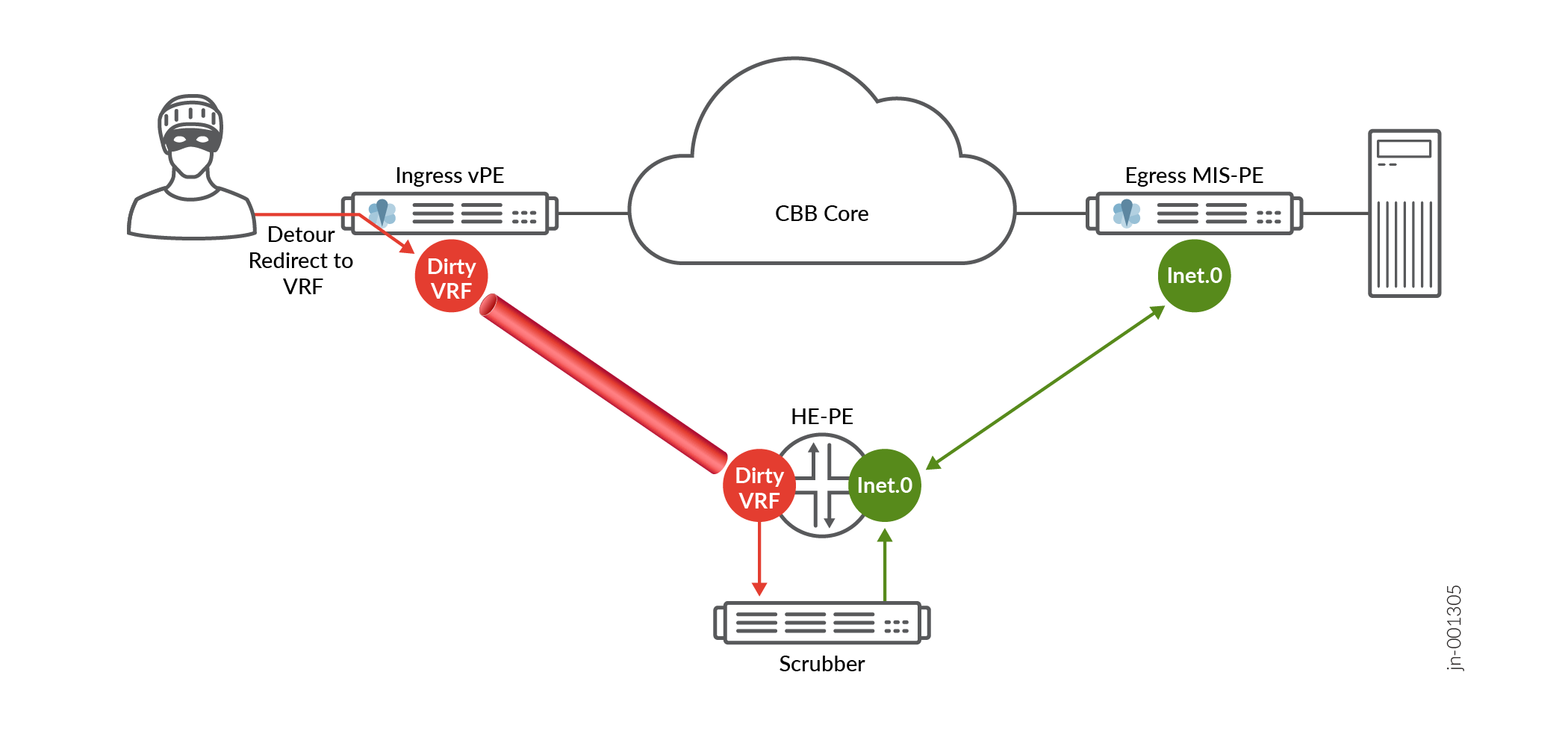
-
When an attack is detected, FlowSpec redirect-to-VRF is applied on the Ingress Provider Edge (PE) router.
-
The dirty VRF then redirects traffic to a scrubber connected to the Head-End PE (HE-PE).
-
Once the traffic is cleaned, the HE-PE forwards it towards the intended destination.
-
-
Figure 9: New Flow
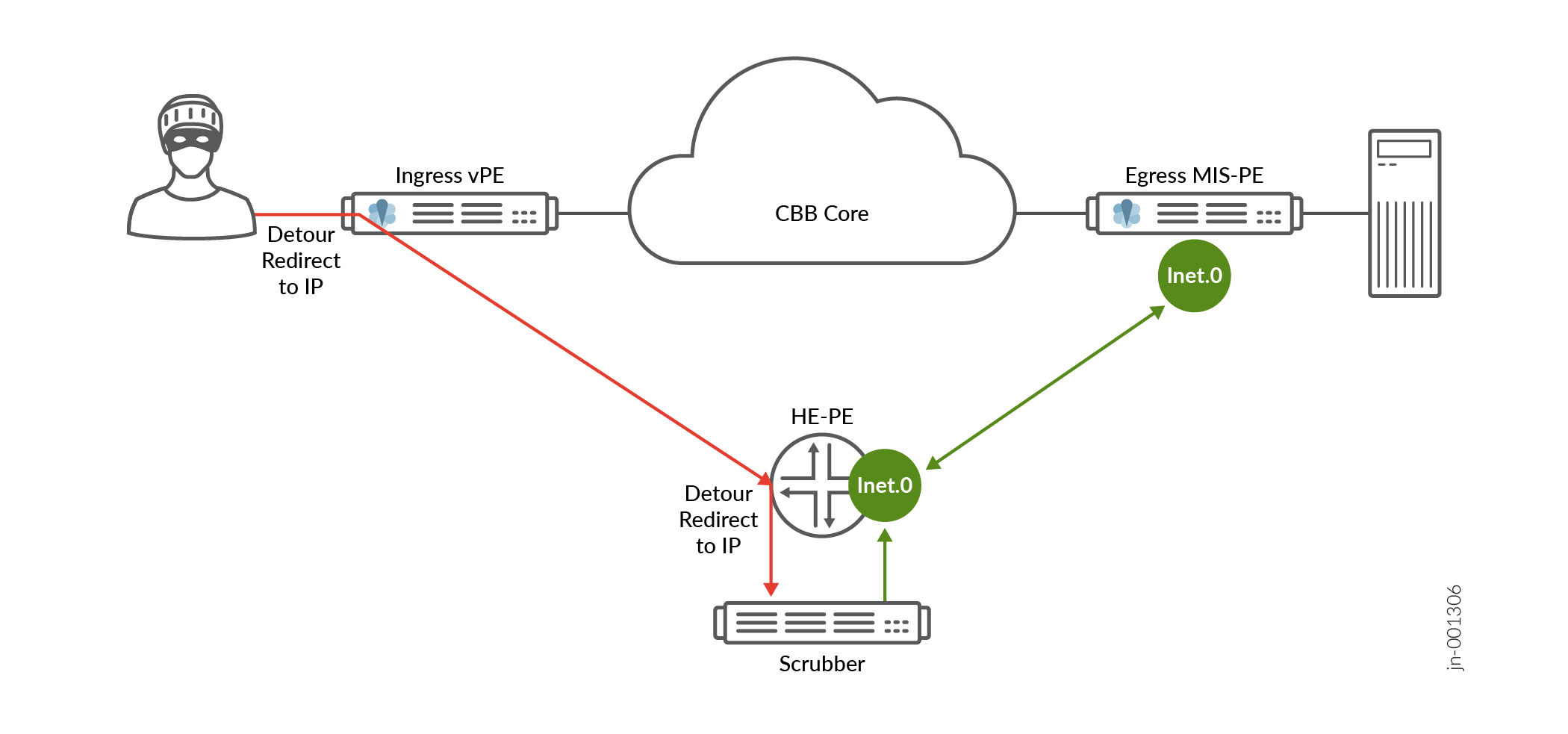
-
Instead of redirect-to-VRF, FlowSpec redirect-to-IP is applied on external-facing interfaces of the ingress PE.
-
Malicious traffic is directly forwarded to the HE-PE.
-
The HE-PE then redirects traffic to the scrubber based on the redirect-to-IP rule.
-
The cleaned traffic is forwarded to its destination without requiring a dedicated dirty VRF.
-
Platforms Targeted
-
vMX, MX Series Routers
Performance and Scaling Targets
-
The feature aims to support 1,000 such FlowSpec routes to effectively manage traffic redirection.
Verification Commands:
show firewall filter FLOWSPEC
This feature ensures improved scalability, reduced latency, and efficient DDoS mitigation by simplifying the redirection process through IP-based traffic handling rather than VRF-based segmentation.
See Also
Configuring BGP Flow Specification Action Redirect to IP to Filter DDoS Traffic
Starting in Junos OS Release 18.4R1, BGP flow specification as described in BGP Flow-Spec Internet draft draft-ietf-idr-flowspec-redirect-ip-02.txt, Redirect to IP Action is supported. Redirect to IP action uses extended BGP community to provide traffic filtering options for DDoS mitigation in service provider networks. Legacy flow specification redirect to IP uses the BGP nexthop attribute. Junos OS advertises redirect to IP flow specification action using the extended community by default. This feature is required to support service chaining in virtual service control gateway (vSCG). Redirect to IP action allows to divert matching flow specification traffic to a globally reachable address that could be connected to a filtering device that can filter the DDoS traffic and send the clean traffic to the egress device.
IPv6 is supported only in legacy redirect-to-Nexthop encoding mode. We do not support the new redirect-to-IP encoding format for IPv6.
Before you begin redirecting traffic to IP for BGP flow specification routes, do the following:
Configure the device interfaces.
Configure OSPF or any other IGP protocol.
Configure MPLS and LDP.
Configure BGP.
Configure the redirect to IP feature using the BGP extended community.
Configure the legacy flow specification redirect to IP feature using the nexthop attribute.
You cannot configure policies to redirect traffic to an IP address using BGP extended community and the legacy redirect to next hop IP address together.
Configure legacy flow specification redirect to IP specified in the internet draft draft-ietf-idr-flowspec-redirect-ip-00.txt , BGP Flow-Spec Extended Community for Traffic Redirect to IP Next Hop include at the hierarchy level.
[edit group bgp-group neighbor bgp neighbor family inet flow]
user@host# set legacy-redirect-ip-action
Define a policy to match the next hop attribute.
[edit policy options]
user@host#policy statement policy_name
user@host#from community community-name
user@host#from next-hop ip-address
For example, define a policy p1 to redirect traffic to next hop IP address 10.1.1.1.
[edit policy options]
user@host#policy statement p1
user@host#from community redirnh
user@host#from next-hop 10.1.1.1
Define a policy to set, add, or delete the BGP community using the legacy flow specification next hop attribute redirect to IP action.
[edit policy-options]
user@host# policy-statement policy_name
user@host# then community set community-name
user@host# then community add community-name
user@host# then community delete community-name
user@host# then next-hop next-hop-address
For example, define a policy p1 and set, add, or delete a BGP community redirnh to redirect the DDoS traffic to the the next hop IP address 10.1.1.1.
[edit policy-options policy-statement p1]
user@host# then community set redirnh
user@host# then community add redirnh
user@host# then community delete redirnh
user@host# then next-hop 10.1.1.1
See Also
Forwarding Traffic Using BGP Flow Specification DSCP Action
Configure BGP Flow Specification (FlowSpec) DSCP action to forward packets using the forwarding class and loss priority information across the network effectively.
Benefits of BGP FlowSpec DSCP action to forward packets
-
Forwards traffic to the intended COS queues, where COS policies are applied to the traffic correctly.
-
Influences local forwarding behavior (for example, selection of the tunnel) based on the provisioned DSCP value.
-
Helps to manage traffic on your network effectively.
When a packet enters a router, the packet goes through the features (such as firewall, COS, etc.) applied at the ingress interface. When you configure BGP FlowSpec filter on the ingress interface, the filter is applied on the packets per routing instance based on the DSCP action. The DSCP action classifies and rewrites the packets, along with the DSCP code change through the BGP FlowSpec filter. Based on the forwarding class and loss priority information, the packets are placed to the correct forwarding queue. Packets travel through flow routes only if specific match conditions are met. The matching conditions can be source and destination IP address, source and destination port, DSCP, protocol number, etc. The forwarding class and loss priority information is updated through the reverse mapping table.
Here is a topology of a BGP session established between the service provider and the enterprise customer networks.
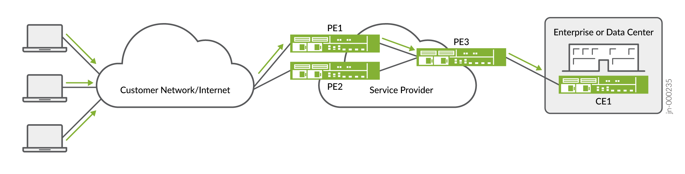
In this topology, a BGP session is configured between the service provider and the enterprise customer network for BGP FlowSpec. BGP FlowSpec filter is applied at both PE1 and PE2 routers. Packets entering these routers are rewritten based on the BGP FlowSpec filter and the DSCP action.
To enable the BGP FlowSpec filter on a
device, you need to add the dscp-mapping-classifier configuration statement
at the [edit forwarding-options family (inet | inet6)] hierarchy
level:
forwarding-options {
    family inet {
        dscp-mapping-classifier ipv4-classifer;
    }
    family inet6 {
        dscp-mapping-classifier ipv6-classifer;
    }
}
The following sample class of service configuration maps DSCP code points to the forwarding class and loss priority:
class-of-service {
	classifiers {
		dscp dscp1 {
        		forwarding-class best-effort {
            		loss-priority low code-points 000000;
        		}
		}
      }
}
Configuring Policies for Flow Route Validation
When flow specification is used to distribute filters through the network to the peering points, the format of the flow specification filters is validated at the source. If you want signal flow routes over EBGP session to the peers, the flow specification filters must be validated at the edge routers.
Policies can be used to perform this additional validation of flow routes. A policy can filter the flow route match conditions to prevent admission of malformed, unsupported or undesired flow routes injected from the source. It can also prevent flow routes from accidentally or maliciously blocking protocol sessions.
Policies can be used to
-
Check if a particular flow specification match/action condition exists
-
Prevent programming invalid or undesired match conditions.
- Configuring Policies to Check if a flow specification match/action condition exists
- Configuring Policies to Check Flow Specification Match Attributes
Configuring Policies to Check if a flow specification match/action condition exists
You can configure policies to check whether a particular flow match/action condition is advertised from the source and take any necessary action. Each flow route has a match condition and an action condition. Configure the following statements specifying the match condition and the action to be taken if a match occurs.
set policy-options flowspec-attribute <> match condition <>
set policy-options flowspec-attribute < Flow Route action >
These policy configurations look for exact or partial matches in the flow route, and when found, the policy will match the flow route. If you configure multiple match conditions, then the matching occurs only when all the conditions are met.
You can use the 'invert' match option to exclude a certain match condition. For example; in the below configuration statements, the policy matches flow routes 'without tcp protocol and then matches 'with the dscp value 'x’. If both matches are found, then the policy accepts the flow routes.
set policy-options flowspec-attribute fl1 invert-match protocol value tcp

set policy-options flowspec-attribute fl1 match dscp value <x>

set policy-options policy-statement pl1 term 1 from flowspec-attribute fl1
set policy-options policy-statement pl1 term 1 then accept
Configuring Policies to Check Flow Specification Match Attributes
You can configure policies to check whether the flow route matches the specific value of a flow match condition. This can prevent flow routes from accidentally or maliciously blocking protocol sessions.
Configure the following statement specifying the specific value of the attribute.
set policy-options flowspec-attribute < match value >
Flow spectification policy match attributes specific to IPv4 do not impact IPv6 flow routes and vice-versa.
Change History Table
Feature support is determined by the platform and release you are using. Use Feature Explorer to determine if a feature is supported on your platform.
extended-community filtering
action.