BGP Optimal Route Reflection
Understanding BGP Optimal Route Reflection
When BGP performs best-path selection, it evaluates multiple attributes in a defined order. One of these steps is to prefer the path whose next hop is resolved through the IGP with the lowest metric. This comparison is performed from the perspective of the router making the path selection decision.
For more information about BGP path selection, see Understanding BGP Path Selection.
In networks where route reflectors are deployed on a per–point of presence basis, this behavior typically produces the desired forwarding outcome. Each route reflector reflects routes to its clients based on IGP costs that closely align with the clients’ forwarding topology.
However, in large-scale networks, a route reflector may serve client and non-client peers that are distributed across multiple geographic locations. In these deployments, the IGP metric used during BGP path selection reflects the topology from the route reflector’s location, not from the perspective of the receiving clients.
As a result, the route that appears optimal to the route reflector may not represent the best forwarding path for all clients. This mismatch can lead to suboptimal traffic forwarding, even though BGP path selection is operating correctly.
BGP optimal route reflection addresses this limitation by allowing path selection to better align with the IGP topology of the clients receiving reflected routes, rather than relying solely on the route reflector’s local view.
You can configure BGP Optimal Route Reflection (BGP-ORR), described in RFC 9107, with IS-IS and OSPF as the interior gateway protocol (IGP) on a route reflector to advertise the best path to the BGP-ORR client groups. This is done by using the shortest IGP metric from a client's perspective, instead of the route reflector's view.
Client groups sharing the same or similar IGP topology can be grouped as one BGP peer
group. You can configure optimal-route-reflection to enable BGP-ORR in
that BGP peer group. You can also configure one of the
reflector
nodes as the primary node (igp-primary) in a BGP peer group so that the
IGP metric from that primary node is used to select the best path and advertise it to
the clients in the same BGP peer group. Optionally, you can also select another
reflector
node as the backup node (igp-backup), which is used when the primary
reflector
node (igp-primary) goes down or is unreachable.
To enable BGP-ORR, include the optimal-route-reflection statement at the
[edit protocols bgp group group-name] hierarchy
level.
BGP-ORR only works when IGP is used for BGP route resolution. BGP-ORR does not work when MPLS/LDP/RSVP is used for route resolution.
For BGP-ORR to work, the BGP prefix should be resolved through an IGP. In normal Layer 3 VPN, or Layer 2 VPN, or VPLS, or MVPN, or EVPN scenarios, the prefixes are resolved over inet.3. In inet.3, the primary route for the protocol-next-hop of the prefix would be either RSVP or LDP ( and not an IGP protocol like IS-IS or OSPF). For BGP-ORR to work, you need to configure the router to use inet.0 for the route-resolution of Layer 3 VPN, or Layer 2 VPN, or VPLS, or MVPN, or EVPN prefixes. You can do this through the following commands:
-
For Layer 3 VPN prefix:
user@host# set routing-options resolution rib bgp.l3vpn.0 resolution-ribs inet.0
-
For Layer 2 VPN, or VPLS prefix:
user@host# set routing-options resolution rib bgp.l2vpn.0 resolution-ribs inet.0
-
For EVPN prefix:
user@host# set routing-options resolution rib bgp.evpn.0 resolution-ribs inet.0
-
For MVPN prefix:
user@host# set routing-options resolution rib bgp.mvpn.0 resolution-ribs inet.0
Another method is to leak the IGP routes into inet.3 and make them as the primary route in inet.3.
Use the following CLI hierarchy to configure BGP-ORR:
[edit protocols bgp]
group group-name{
    optimal-route-reflection {
        igp-primary ipv4-address;
        igp-backup ipv4-address;
    }
}
See Also
Configuring BGP Optimal Route Reflection on a Route Reflector to Advertise the Best Path
You can configure BGP Optimal Route Reflection (BGP-ORR) with IS-IS and OSPF as the interior gateway protocol (IGP) on a route reflector to advertise the best path to the BGP-ORR client groups. This is done by using the shortest IGP metric from a client's perspective, instead of the route reflector's view.
To enable BGP-ORR, include the optimal-route-reflection statement at the [edit protocols bgp group group-name] hierarchy level.
Client groups sharing the same or similar IGP topology can be
grouped as one BGP peer group. You can configure optimal-route-reflection to enable BGP-ORR in that BGP peer group.
To configure BGP-ORR:
Use the following CLI commands to monitor and troubleshoot the configuration for BGP-ORR:
show bgp group—View the primary and backup configurations of BGP-ORR.show isis bgp-orr—View the IS-IS BGP-ORR metric (RIB).show ospf bgp-orr—View the OSPF BGP-ORR metric (RIB).show ospf route—View the entries in the OSPF routing tableshow route—View the active entries in the routing tables.show route advertising protocol bgp peer—Verify whether the routes are being advertised according to the BGP-ORR rules.
See Also
Example: Configuring Optimal Route Reflection in BGP Networks
Use this example to configure optimal route reflection with OSPF as the interior gateway protocol (IGP) on a route reflector to advertise the best path to the BGP client groups. The route reflector calculates the optimal route using the shortest IGP metric from a client's perspective.
Our content testing team has validated this example.
|
Readability Score |
64.26 |
|
Reading Time |
30 minutes |
|
Configuration Time |
30 minutes |
- Example Prerequisites
- Before You Begin
- Functional Overview
- Topology Overview
- Topology Illustration
- Configure Optimal Route Reflection on RR
- Verification
- Set Commands on all Devices
- Show Configuration Output on all Devices
Example Prerequisites
|
Hardware requirements |
Five MX Series routers. |
|
Software requirements |
Junos OS Release 15.2R1 or later |
Before You Begin
|
Benefits |
|
|
Know more |
|
|
Hands-on experience |
|
|
Learn more |
Functional Overview
Routers in the same BGP autonomous system usually exchange routes with each other. IBGP requires a full-mesh connectivity, which is cumbersome and slow. Maintaining a full mesh does not scale well in large deployments. Instead of creating a full mesh, route reflectors readvertise routes learned from an internal peer to other internal peers, which simplifies the full-mesh configuration. Route reflection requires the route reflector be fully meshed with all internal peers. Client groups sharing similar IGP topology can be grouped as one BGP peer group. Configure one of the reflector nodes as the primary node in a BGP peer group and an optional backup node. Optimal route reflection only works with IGP and does not work when you use MPLSLDP or RSVP for route resolution.
|
Technologies used |
Routing Protocols: OSPF, BGP |
|
Primary verification tasks |
|
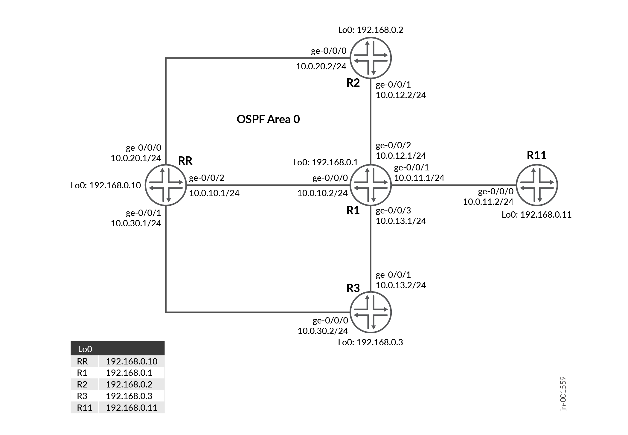
Topology Overview
Device RR is the Route Reflector using ORR (Optimal Route Reflection). Device R1 is the ingress PE and Devices R2 and R3 are the egress PEs. With ORR configured, RR reflects routes optimally based on the ingress PE’s (R1) view instead of its own. OSPF is configured as the IGP and there is IBGP peering between the devices.
For illustration purpose, we increase the R1-to-R3 metric to 100 and have Devices R2 and R3 advertise the same prefix of 10.10.10.0/24. On R1, the ‘show route’ output should have R2 as the protocol next-hop (egress PE). On deactivating the BGP-ORR configuration on RR and repeating the same steps, we see that R3 is the egress PE for the advertised prefix.
|
Hostname |
Role |
Function |
|---|---|---|
| RR | RR is configured as the route reflecor and is configured with optimal route reflection. | RR is configured with OSPF and internal BGP. RR reflects routes optimally based on R1's view instead of its own. |
| R1 | The device is the ingress PE | OSPF is configured as the IGP and BGP is configures for internal BGP peering between the devices. |
|
R2, R3 and R11 |
These devices are the egress PEs. |
OSPF is configured as the IGP and internal BGP. |
Topology Illustration
Configure Optimal Route Reflection on RR
For complete sample configurations on the DUT and other devices, see:
Verification
| Command | Verification Task |
|---|---|
| show bgp group | Verify the assigned BGP-Optimal Route Reflector |
| show ospf bgp-orr | Verify the configured OSPF BGP-Optimal Route Reflector metric |
| show route advertising-protocol bgp | Verify that the routes are optimally advertised by the Route Reflector |
- Verify the assigned BGP-ORR
- Verify the configured OSPF BGP-ORR metric in the Routing information base (RIB)
- Verify that the routes are optimally advertised by the Route Reflector
Verify the assigned BGP-ORR
Purpose
View the configured BGP group and devices assigned as primary and backup for BGP-ORR.
Action
From operational mode, run the show bgp
group command to verify the assigned
BGP-ORR.
View the configured BGP group and devices assigned as primary and backup for BGP-ORR.
user@RR> show bgp group
Group Type: Internal    AS: 65412                  Local AS: 65412
  Name: Client          Index: 0                   Flags: <>
  Options: <Cluster>
  Options: <GracefulShutdownRcv>
  Holdtime: 90 Preference: 0
  Graceful Shutdown Receiver local-preference: 0
  Optimal route reflection: igp-primary 192.168.0.1 igp-backup 192.168.0.11
  Total peers: 4        Established: 4
  192.168.0.1+59852
  192.168.0.2+56933
  192.168.0.3+52883
  192.168.0.11+65170
  inet.0: 1/2/2/0
Default eBGP mode: advertise - accept, receive - accept

Groups: 1  Peers: 4    External: 0    Internal: 4    Down peers: 0   Flaps: 0
Table          Tot Paths  Act Paths Suppressed    History Damp State    Pending
inet.0
                       2          1          0          0          0          0
Meaning
The output includes the configured primary and backup optimal route reflectors and their loopback addresses.
Verify the configured OSPF BGP-ORR metric in the Routing information base (RIB)
Purpose
Verify the configured OSPF BGP-ORR metric in the Routing information base (RIB)
Action
From operational mode, run the show ospf
bgp-orr command.
user@RR> show ospf bgp-orr
Topology default Route Table:

BGP ORR Peer Group: Client
  Primary: 192.168.0.1, active
  Backup: 192.168.0.11
Prefix             Path  Route      Metric
                   Type  Type
192.168.0.2        Intra Router          1
192.168.0.3        Intra Router          2
192.168.0.10       Intra Router          1
192.168.0.11       Intra Router          1
10.0.10.0/24       Intra Network         1
10.0.11.0/24       Intra Network         1
10.0.12.0/24       Intra Network         1
10.0.13.0/24       Intra Network         3
10.0.20.0/24       Intra Network         2
10.0.30.0/24       Intra Network         2
192.168.0.1/32     Intra Network         0
192.168.0.2/32     Intra Network         1
192.168.0.3/32     Intra Network         2
192.168.0.10/32    Intra Network         1
192.168.0.11/32    Intra Network         1
Meaning
The output displays the assigned metric of the primary and backup optimal route reflector.
Verify that the routes are optimally advertised by the Route Reflector
Purpose
Verify whether the routes are being advertised according to the BGP-ORR rules.
Action
From operational mode, run the show route
advertising-protocol bgp command.
user@RR> show route advertising-protocol bgp 192.168.0.1

inet.0: 22 destinations, 23 routes (22 active, 0 holddown, 0 hidden)
  Prefix                  Nexthop              MED     Lclpref    AS path
* 10.10.10.0/24           192.168.0.2                  100        I


user@R1> show route 10.10.10.0/24

inet.0: 23 destinations, 24 routes (23 active, 0 holddown, 0 hidden)
+ = Active Route, - = Last Active, * = Both

10.10.10.0/24      *[BGP/170] 00:01:38, localpref 100, from 192.168.0.10
                      AS path: I, validation-state: unverified
                    >  to 10.0.12.2 via ge-0/0/2.0
Meaning
The output illustrates that the IP address of Device R2 is selected as the next hop when BGP ORR is enabled on the RR.
When you deactivate BGP ORR configuration on the RR, Device R3 is chosen as the egress PE chosen to reach Device R1.
[edit]
user@RR# show | compare rollback 1
[edit protocols bgp group Client]
!      inactive: optimal-route-reflection { ... }

user@R1> show route 10.10.10.0/24

inet.0: 22 destinations, 22 routes (22 active, 0 holddown, 0 hidden)
+ = Active Route, - = Last Active, * = Both

10.10.10.0/24      *[BGP/170] 00:00:01, localpref 100, from 192.168.0.10
                      AS path: I, validation-state: unverified
                    >  to 10.0.13.2 via ge-0/0/3.0
Meaning
The output illustrates that the IP address of Device R3 is selected as the next hop when BGP ORR is deactivated on the RR.
Set Commands on all Devices
To quickly configure this example, copy the following commands, paste them into a text file, remove any line breaks, change any details necessary to match your network configuration, and then copy and paste the commands into the CLI at the [edit] hierarchy level.
RR
set system host-name RR
set system ports console log-out-on-disconnect
set interfaces ge-0/0/0 unit 0 description "Connected to R2"
set interfaces ge-0/0/0 unit 0 family inet address 10.0.20.1/24
set interfaces ge-0/0/1 unit 0 description "Connected to R3"
set interfaces ge-0/0/1 unit 0 family inet address 10.0.30.1/24
set interfaces ge-0/0/2 unit 0 description "Connected to R1"
set interfaces ge-0/0/2 unit 0 family inet address 10.0.10.1/24
set interfaces lo0 unit 0 family inet address 192.168.0.10/32
set routing-options router-id 192.168.0.10
set routing-options autonomous-system 65412
set protocols bgp group Client type internal
set protocols bgp group Client local-address 192.168.0.10
set protocols bgp group Client family inet unicast
set protocols bgp group Client cluster 192.168.0.10
set protocols bgp group Client peer-as 65412
set protocols bgp group Client optimal-route-reflection igp-primary 192.168.0.1
set protocols bgp group Client optimal-route-reflection igp-backup 192.168.0.11
set protocols bgp group Client neighbor 192.168.0.1
set protocols bgp group Client neighbor 192.168.0.2
set protocols bgp group Client neighbor 192.168.0.3
set protocols bgp group Client neighbor 192.168.0.11
set protocols ospf area 0.0.0.0 interface all
set protocols ospf area 0.0.0.0 interface fxp0.0 disable
R1 (Ingress PE)
set system host-name R1
set interfaces ge-0/0/0 unit 0 description "Connected to RR"
set interfaces ge-0/0/0 unit 0 family inet address 10.0.10.2/24
set interfaces ge-0/0/1 unit 0 description "Connected to R11"
set interfaces ge-0/0/1 unit 0 family inet address 10.0.11.1/24
set interfaces ge-0/0/2 unit 0 description "Connected to R2"
set interfaces ge-0/0/2 unit 0 family inet address 10.0.12.1/24
set interfaces ge-0/0/3 unit 0 description "Connected to R3"
set interfaces ge-0/0/3 unit 0 family inet address 10.0.13.1/24
set interfaces lo0 unit 0 family inet address 192.168.0.1/32
set routing-options router-id 192.168.0.1
set routing-options autonomous-system 65412
set protocols bgp group Client type internal
set protocols bgp group Client local-address 192.168.0.1
set protocols bgp group Client family inet unicast
set protocols bgp group Client neighbor 192.168.0.10 peer-as 65412
set protocols ospf area 0.0.0.0 interface all
set protocols ospf area 0.0.0.0 interface fxp0.0 disable
set protocols ospf area 0.0.0.0 interface ge-0/0/3.0 metric 100
R2
set system host-name R2
set interfaces ge-0/0/0 unit 0 description "Connected to RR"
set interfaces ge-0/0/0 unit 0 family inet address 10.0.20.2/24
set interfaces ge-0/0/1 unit 0 description "Connected to R1"
set interfaces ge-0/0/1 unit 0 family inet address 10.0.12.2/24
set interfaces lo0 unit 0 family inet address 192.168.0.2/32
set policy-options policy-statement export-static term 1 from protocol static
set policy-options policy-statement export-static term 1 from route-filter 10.10.10.0/24 exact
set policy-options policy-statement export-static term 1 then accept
set routing-options router-id 192.168.0.2
set routing-options autonomous-system 65412
set routing-options static route 10.10.10.0/24 discard
set protocols bgp group Client type internal
set protocols bgp group Client local-address 192.168.0.2
set protocols bgp group Client family inet unicast
set protocols bgp group Client export export-static
set protocols bgp group Client neighbor 192.168.0.10 peer-as 65412
set protocols ospf area 0.0.0.0 interface all
set protocols ospf area 0.0.0.0 interface fxp0.0 disable
R3
set system host-name R3
set interfaces ge-0/0/0 unit 0 description "Connected to RR"
set interfaces ge-0/0/0 unit 0 family inet address 10.0.30.2/24
set interfaces ge-0/0/1 unit 0 description "Connected to R1"
set interfaces ge-0/0/1 unit 0 family inet address 10.0.13.2/24
set interfaces lo0 unit 0 family inet address 192.168.0.3/32
set policy-options policy-statement export-static term 1 from protocol static
set policy-options policy-statement export-static term 1 from route-filter 10.10.10.0/24 exact
set policy-options policy-statement export-static term 1 then accept
set routing-options router-id 192.168.0.3
set routing-options autonomous-system 65412
set routing-options static route 10.10.10.0/24 discard
set protocols bgp group Client type internal
set protocols bgp group Client local-address 192.168.0.3
set protocols bgp group Client family inet unicast
set protocols bgp group Client export export-static
set protocols bgp group Client neighbor 192.168.0.10 peer-as 65412
set protocols ospf area 0.0.0.0 interface all
set protocols ospf area 0.0.0.0 interface fxp0.0 disable
R11
set system host-name R11
set interfaces ge-0/0/0 unit 0 description "Connected to R1"
set interfaces ge-0/0/0 unit 0 family inet address 10.0.11.2/24
set interfaces lo0 unit 0 family inet address 192.168.0.11/32
set routing-options router-id 192.168.0.11
set routing-options autonomous-system 65412
set protocols bgp group Client type internal
set protocols bgp group Client local-address 192.168.0.11
set protocols bgp group Client family inet unicast
set protocols bgp group Client neighbor 192.168.0.10 peer-as 65412
set protocols ospf area 0.0.0.0 interface all
set protocols ospf area 0.0.0.0 interface fxp0.0 disable
Show Configuration Output on all Devices
Show command output on the RR and other devices.
RR
interfaces {
    ge-0/0/0 {
        unit 0 {
            description "Connected to R2";
            family inet {
                address 10.0.20.1/24;
            }
        }
    }
    ge-0/0/1 {
        unit 0 {
            description "Connected to R3";
            family inet {
                address 10.0.30.1/24;
            }
        }
    }
    ge-0/0/2 {
        unit 0 {
            description "Connected to R1";
            family inet {
                address 10.0.10.1/24;
            }
        }
    }
    lo0 {
        unit 0 {
            family inet {
                address 192.168.0.10/32;
            }
        }
    }
}
routing-options {
    router-id 192.168.0.10;
    autonomous-system 65412;
}
protocols {
    bgp {
        group Client {
            type internal;
            local-address 192.168.0.10;
            family inet {
                unicast;
            }
            cluster 192.168.0.10;
            peer-as 65412;
            optimal-route-reflection {
                igp-primary 192.168.0.1;
                igp-backup 192.168.0.11;
            }
            neighbor 192.168.0.1;
            neighbor 192.168.0.2;
            neighbor 192.168.0.3;
            neighbor 192.168.0.11;
        }
    }
    ospf {
        area 0.0.0.0 {
            interface all;
            interface fxp0.0 {
                disable;
            }
        }
    }
}
Ingress Device R1
R1
interfaces {
    ge-0/0/0 {
        unit 0 {
            description "Connected to RR";
            family inet {
                address 10.0.10.2/24;
            }
        }
    }
    ge-0/0/1 {
        unit 0 {
            description "Connected to R11";
            family inet {
                address 10.0.11.1/24;
            }
        }
    }
    ge-0/0/2 {
        unit 0 {
            description "Connected to R2";
            family inet {
                address 10.0.12.1/24;
            }
        }
    }
    ge-0/0/3 {
        unit 0 {
            description "Connected to R3";
            family inet {
                address 10.0.13.1/24;
            }
        }
    }
    lo0 {
        unit 0 {
            family inet {
                address 192.168.0.1/32;
            }
        }
    }
}
routing-options {
    router-id 192.168.0.1;
    autonomous-system 65412;
}
protocols {
    bgp {
        group Client {
            type internal;
            local-address 192.168.0.1;
            family inet {
                unicast;
            }
            neighbor 192.168.0.10 {
                peer-as 65412;
            }
        }
    }
    ospf {
        area 0.0.0.0 {
            interface all;
            interface fxp0.0 {
                disable;
            }
            interface ge-0/0/3.0 {
                metric 100;
            }
        }
    }
}
Device R2
R2
interfaces {
    ge-0/0/0 {
        unit 0 {
            description "Connected to RR";
            family inet {
                address 10.0.20.2/24;
            }
        }
    }
    ge-0/0/1 {
        unit 0 {
            description "Connected to R1";
            family inet {
                address 10.0.12.2/24;
            }
        }
    }
    lo0 {
        unit 0 {
            family inet {
                address 192.168.0.2/32;
            }
        }
    }
}
policy-options {
    policy-statement export-static {
        term 1 {
            from {
                protocol static;
                route-filter 10.10.10.0/24 exact;
            }
            then accept;
        }
    }
}
routing-options {
    router-id 192.168.0.2;
    autonomous-system 65412;
    static {
        route 10.10.10.0/24 discard;
    }
}
protocols {
    bgp {
        group Client {
            type internal;
            local-address 192.168.0.2;
            family inet {
                unicast;
            }
            export export-static;
            neighbor 192.168.0.10 {
                peer-as 65412;
            }
        }
    }
    ospf {
        area 0.0.0.0 {
            interface all;
            interface fxp0.0 {
                disable;
            }
        }
    }
}
Device R3
R3
interfaces {
    ge-0/0/0 {
        unit 0 {
            description "Connected to RR";
            family inet {
                address 10.0.30.2/24;
            }
        }
    }
    ge-0/0/1 {
        unit 0 {
            description "Connected to R1";
            family inet {
                address 10.0.13.2/24;
            }
        }
    }
    lo0 {
        unit 0 {
            family inet {
                address 192.168.0.3/32;
            }
        }
    }
}
policy-options {
    policy-statement export-static {
        term 1 {
            from {
                protocol static;
                route-filter 10.10.10.0/24 exact;
            }
            then accept;
        }
    }
}
routing-options {
    router-id 192.168.0.3;
    autonomous-system 65412;
    static {
        route 10.10.10.0/24 discard;
    }
}
protocols {
    bgp {
        group Client {
            type internal;
            local-address 192.168.0.3;
            family inet {
                unicast;
            }
            export export-static;
            neighbor 192.168.0.10 {
                peer-as 65412;
            }
        }
    }
    ospf {
        area 0.0.0.0 {
            interface all;
            interface fxp0.0 {
                disable;
            }
        }
    }
}
Device R11
R11
interfaces {
    ge-0/0/0 {
        unit 0 {
            description "Connected to R1";
            family inet {
                address 10.0.11.2/24;
            }
        }
    }
    lo0 {
        unit 0 {
            family inet {
                address 192.168.0.11/32;
            }
        }
    }
}
routing-options {
    router-id 192.168.0.11;
    autonomous-system 65412;
}
protocols {
    bgp {
        group Client {
            type internal;
            local-address 192.168.0.11;
            family inet {
                unicast;
            }
            neighbor 192.168.0.10 {
                peer-as 65412;
            }
        }
    }
    ospf {
        area 0.0.0.0 {
            interface all;
            interface fxp0.0 {
                disable;
            }
        }
    }
}