BGP Route Reflectors
Understanding BGP Route Reflectors
This topic discusses using BGP route reflectors to simplify configuration and aid in scaling.
In a BGP Autonomous System (AS), routes must be distributed among all AS border routers. The Border Gateway Protocol (BGP) achieves this through internal BGP (IBGP) peering sessions. By default, routes learned from one IBGP peer are not advertised to other IBGP peers. This restriction requires a full mesh of IBGP sessions between all routers in the AS to ensure complete route visibility.
However, maintaining a full mesh increases configuration complexity and limits scalability. Each new IBGP peer must establish sessions with every other peer in the AS. The total number of sessions required for a full mesh is calculated using the formula v * (v - 1)/2, where v represents the number of BGP peers.
In addition to configuration overhead, a full mesh can increase route scaling. Every IBGP peer receives all routes, even if many are suboptimal for its location in the network.
BGP route reflection, defined in RFC 4456, addresses the scalability challenges of IBGP full mesh topologies. Route reflection allows a router, known as a route reflector (RR), to redistribute routes learned from one IBGP peer to other IBGP peers. This relaxes the default BGP rule that prevents IBGP-to-IBGP advertisement of routes.
Because route reflection introduces the possibility of routing loops, RFC 4456 defines two new BGP path attributes that ensure loop prevention and consistent path selection:
ORIGINATOR_ID – Identifies the router ID of the BGP neighbor that originally advertised the route. The ORIGINATOR_ID attribute is attached only when the route is first reflected.
CLUSTER_LIST – Records the cluster IDs of the route reflectors that have reflected the route as it propagates through the network.
For details about how these attributes influence BGP best path selection, see Understanding BGP Path Selection.
Because of the internal BGP (IBGP) full-mesh requirement, most networks use route reflectors to simplify configuration. Using a route reflector, routers are grouped into clusters, which are identified by numeric identifiers unique to the autonomous system. Within the cluster, you must configure a BGP session from a single router (the route reflector) to each internal peer. With this configuration, the IBGP full-mesh requirement is met.
To use route reflection in an AS, you designate one or more routers as a route reflector—typically, one per point of presence (POP). Route reflectors have the ability to readvertise routes learned from an internal peer to other internal peers. Rather than requiring all internal peers to be fully meshed with each other, route reflection requires only that the route reflectors be fully meshed with all internal peers. The route reflector and all of its internal peers form a cluster, as shown in Figure 1.
For some Juniper Networks devices, you must have an Advanced BGP Feature license installed on each device that uses a route reflector. For license details, see the Software Installation and Upgrade Guide.
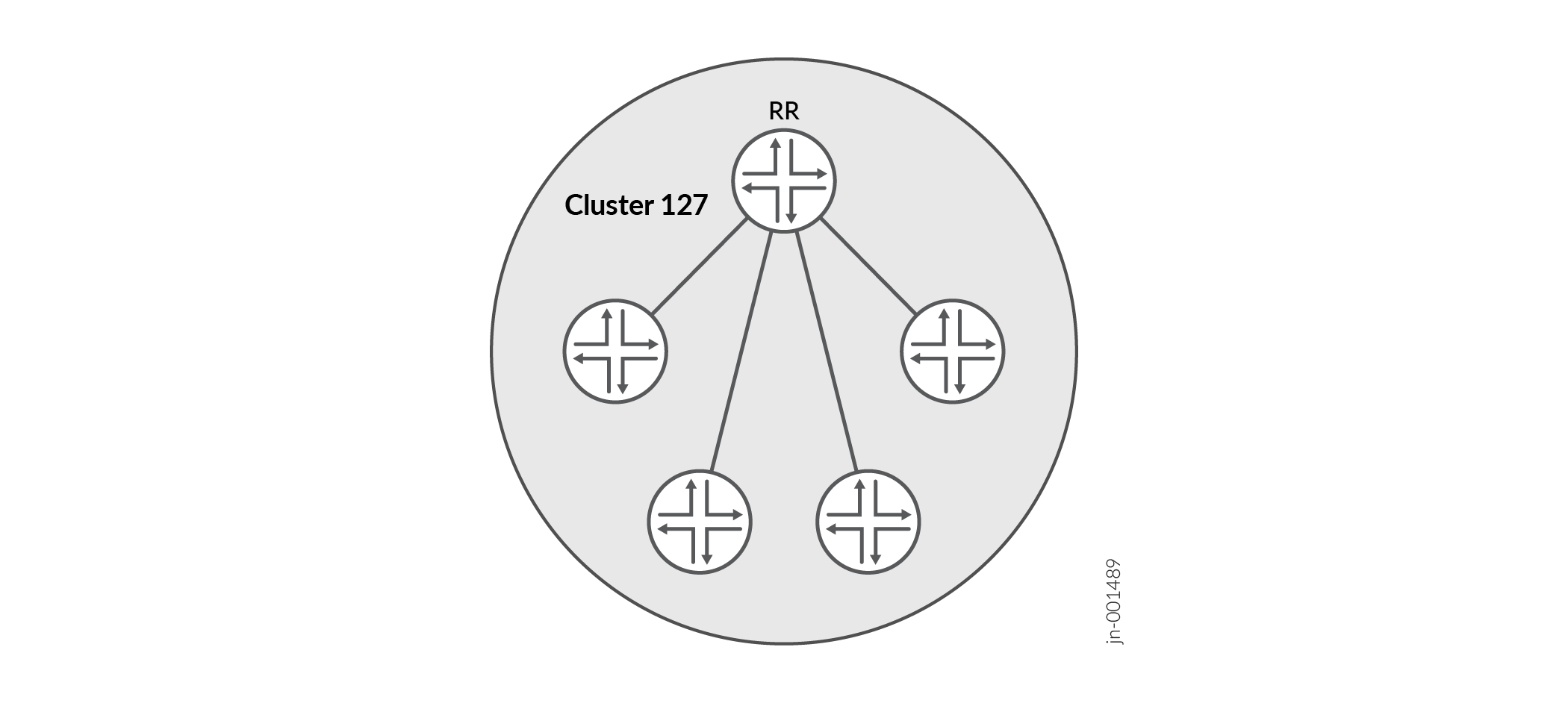
Figure 1 shows Router RR configured as the route reflector for Cluster 127. The other routers are designated internal peers within the cluster. BGP routes are advertised to Router RR by any of the internal peers. RR then readvertises those routes to all other peers within the cluster.
You can configure multiple clusters and link them by configuring a full mesh of route reflectors (see Figure 2).
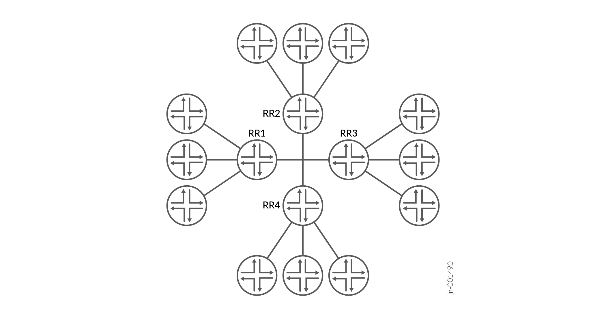
Figure 2 shows Route Reflectors RR 1, RR 2, RR 3, and RR 4 as fully meshed internal peers. When a router advertises a route to RR 1, RR 1 readvertises the route to the other route reflectors, which, in turn, readvertise the route to the remaining routers within the AS. Route reflection allows the route to be propagated throughout the AS without the scaling problems created by the full mesh requirement.
A route reflector that supports multiple clusters does not accept a route with the same cluster ID from a non-client router. Therefore, you must configure a different cluster ID for a redundant RR to reflect the route to other clusters.
A client is an IBGP router that receives routes from the route reflector. A non-client is another IBGP neighbor. The route reflector adverises routes learned from non-clients only to its clients, not to non-clients. However, a route reflector advertises routes learned from clients to both clients and non-clients.
However, as clusters become large, a full mesh with a route reflector becomes difficult to scale, as does a full mesh between route reflectors. To help offset this problem, you can group clusters of routers together into clusters of clusters for hierarchical route reflection (see Figure 3).
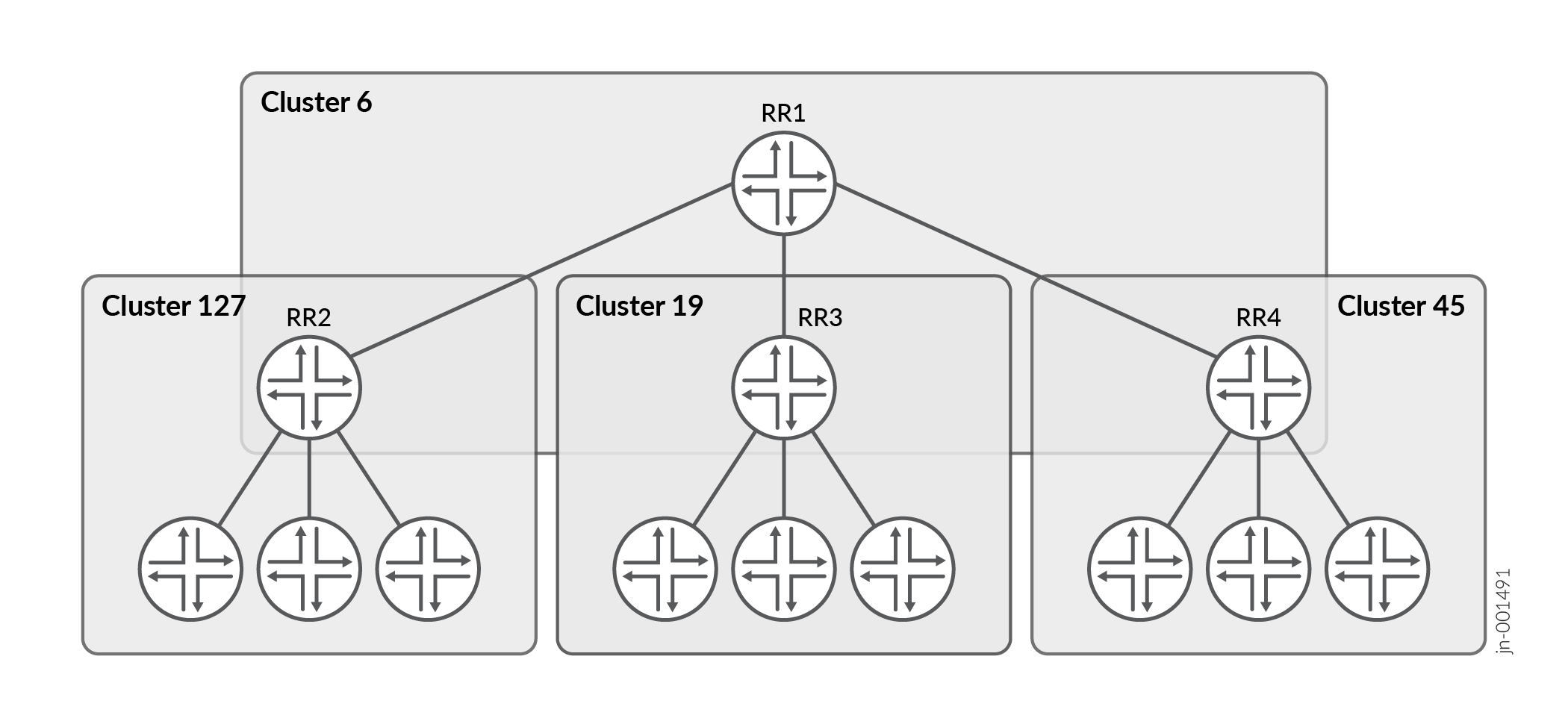
Figure 3 shows RR 2, RR 3, and RR 4 as the route reflectors for Clusters 127, 19, and 45, respectively. Rather than fully mesh those route reflectors, the network administrator has configured them as part of another cluster (Cluster 6) for which RR 1 is the route reflector. When a router advertises a route to RR 2, RR 2 readvertises the route to all the routers within its own cluster, and then readvertises the route to RR 1. RR 1 readvertises the route to the routers in its cluster, and those routers propagate the route down through their clusters.
See Also
Non-forwarding Route Reflectors
In many networks, BGP route reflectors are deployed to improve scalability but are not directly involved in forwarding traffic. These route reflectors maintain BGP control-plane functions without participating in data forwarding. When a route reflector is not in the traffic path, it does not need to install the routes it reflects into its forwarding table. Such devices are referred to as non-forwarding route reflectors.
You can configure non-forwarding route reflectors in one of the following ways:
-
Using the
no-installstatement – Introduced in Junos OS Release 15.1, theno-installstatement prevents BGP routes from being installed in the forwarding table. You can configure this option per address family at the following hierarchy level:[edit protocols bgp family family-name] set no-install
-
Using a forwarding-table export policy – In Junos OS releases earlier than 15.1, you can achieve similar behavior by configuring a forwarding-table export policy that rejects routes learned from BGP.
Non-forwarding route reflectors help reduce the resource load on devices that primarily serve as control-plane routers, especially in large-scale service provider networks.
Example: Configuring a Route Reflector
This example shows how to configure a route reflector.
Requirements
No special configuration beyond device initialization is required before you configure this example.
Overview
Generally, internal BGP (IBGP)-enabled devices need to be fully
meshed, because IBGP does not readvertise updates to other IBGP-enabled
devices. The full mesh is a logical mesh achieved through configuration
of multiple neighbor statements on each IBGP-enabled device.
The full mesh is not necessarily a physical full mesh. Maintaining
a full mesh (logical or physical) does not scale well in large deployments.
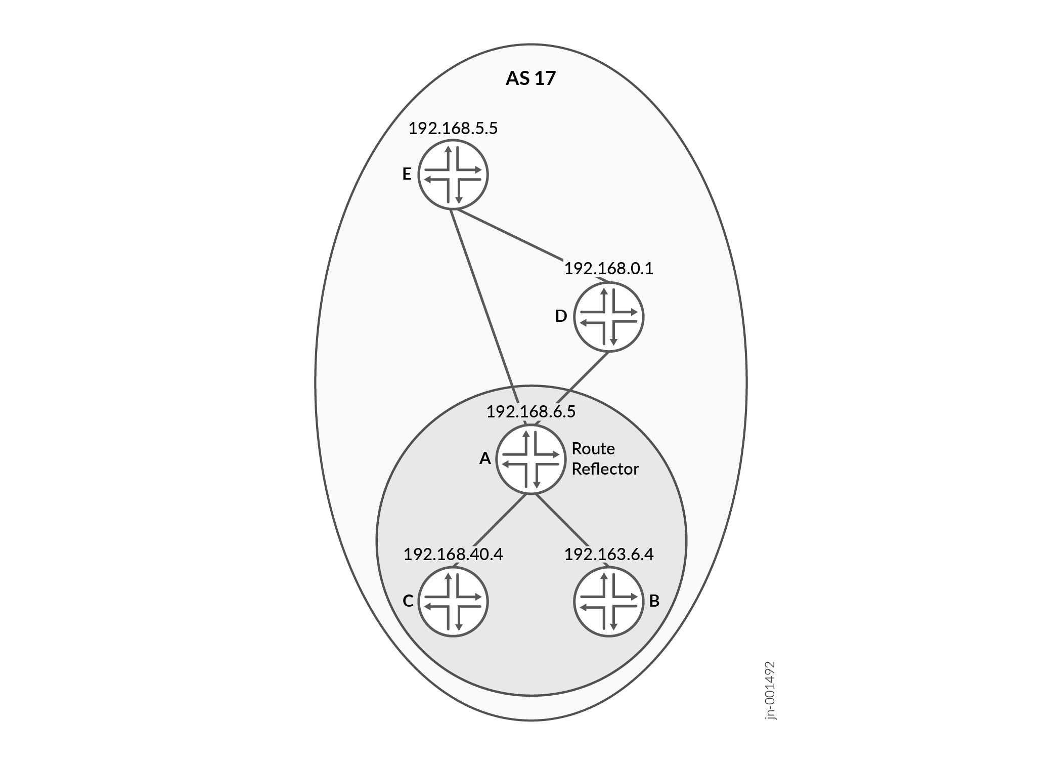
Figure 4 shows an IBGP network with Device A acting as a route reflector. Device B and Device C are clients of the route reflector. Device D and Device E are outside the cluster, so they are non-clients of the route reflector.
On Device A (the route reflector), you must form peer relationships with all of the
IBGP-enabled devices by including the neighbor statement for the
clients (Device B and Device C) and the non-clients (Device D and Device E). You
must also include the cluster statement and a cluster identifier.
The cluster identifier can be any 32-bit value. This example uses the loopback
interface IP address of the route reflector.
On Device B and Device C, the route reflector clients, you only
need one neighbor statement that forms a peer relationship
with the route reflector, Device A.
On Device D and Device E, the non-clients, you need a neighbor
statement for each non-client device (D-to-E and E-to-D). You also need a
neighbor statement for the route reflector (D-to-A and E-to-A).
Device D and Device E do not need neighbor statements for the
client devices (Device B and Device C).
Device D and Device E are considered to be non-clients because they have explicitly
configured peer relationships with each other. To make them RRroute reflector
clients, remove the neighbor 192.168.5.5 statement from the
configuration on Device D, and remove the neighbor 192.168.0.1
statement from the configuration on Device E.
Configuration
Procedure
CLI Quick Configuration
To quickly configure this example, copy the
following commands, paste them into a text file, remove any line breaks,
change any details necessary to match your network configuration,
and then copy and paste the commands into the CLI at the [edit] hierarchy level.
This example redistributes OSPF-learned routes into BGP using the
send-ospf export policy:
set protocols bgp group internal-peers export send-ospf
Redistributing OSPF into BGP is not normally required for route reflector operation. It is used here only to create BGP routes that the route reflector can advertise to its clients, allowing you to observe how route reflection behaves in a simple lab topology.
In a production deployment, route reflectors typically reflect BGP routes learned from clients and do not redistribute IGP routes into BGP unless this behavior is specifically desired.
In this example, routers A, D, and E are non-client IBGP peers and are configured in a full mesh to ensure consistent route exchange outside the route reflector client cluster.
Device A
set interfaces fe-0/0/0 unit 1 description to-B
set interfaces fe-0/0/0 unit 1 family inet address 10.10.10.1/30
set interfaces fe-0/0/1 unit 3 description to-D
set interfaces fe-0/0/1 unit 3 family inet address 10.10.10.9/30
set interfaces lo0 unit 1 family inet address 192.168.6.5/32
set protocols bgp group internal-peers type internal
set protocols bgp group internal-peers local-address 192.168.6.5
set protocols bgp group internal-peers export send-ospf
set protocols bgp group internal-peers cluster 192.168.6.5
set protocols bgp group internal-peers neighbor 192.163.6.4
set protocols bgp group internal-peers neighbor 192.168.40.4
set protocols bgp group internal-peers neighbor 192.168.0.1
set protocols bgp group internal-peers neighbor 192.168.5.5
set protocols ospf area 0.0.0.0 interface lo0.1 passive
set protocols ospf area 0.0.0.0 interface fe-0/0/0.1
set protocols ospf area 0.0.0.0 interface fe-0/0/1.3
set policy-options policy-statement send-ospf term 2 from protocol ospf
set policy-options policy-statement send-ospf term 2 then accept
set routing-options router-id 192.168.6.5
set routing-options autonomous-system 17
Device B
set interfaces fe-0/0/0 unit 2 description to-A
set interfaces fe-0/0/0 unit 2 family inet address 10.10.10.2/30
set interfaces fe-0/0/1 unit 5 description to-C
set interfaces fe-0/0/1 unit 5 family inet address 10.10.10.5/30
set interfaces lo0 unit 2 family inet address 192.163.6.4/32
set protocols bgp group internal-peers type internal
set protocols bgp group internal-peers local-address 192.163.6.4
set protocols bgp group internal-peers export send-ospf
set protocols bgp group internal-peers neighbor 192.168.6.5
set protocols ospf area 0.0.0.0 interface lo0.2 passive
set protocols ospf area 0.0.0.0 interface fe-0/0/0.2
set protocols ospf area 0.0.0.0 interface fe-0/0/1.5
set policy-options policy-statement send-ospf term 2 from protocol ospf
set policy-options policy-statement send-ospf term 2 then accept
set routing-options router-id 192.163.6.4
set routing-options autonomous-system 17
Device C
set interfaces fe-0/0/0 unit 6 description to-B
set interfaces fe-0/0/0 unit 6 family inet address 10.10.10.6/30
set interfaces lo0 unit 3 family inet address 192.168.40.4/32
set protocols bgp group internal-peers type internal
set protocols bgp group internal-peers local-address 192.168.40.4
set protocols bgp group internal-peers export send-ospf
set protocols bgp group internal-peers neighbor 192.168.6.5
set protocols ospf area 0.0.0.0 interface lo0.3 passive
set protocols ospf area 0.0.0.0 interface fe-0/0/0.6
set policy-options policy-statement send-ospf term 2 from protocol ospf
set policy-options policy-statement send-ospf term 2 then accept
set routing-options router-id 192.168.40.4
set routing-options autonomous-system 17
Device D
set interfaces fe-0/0/0 unit 4 description to-A
set interfaces fe-0/0/0 unit 4 family inet address 10.10.10.10/30
set interfaces fe-0/0/1 unit 7 description to-E
set interfaces fe-0/0/1 unit 7 family inet address 10.10.10.13/30
set interfaces lo0 unit 4 family inet address 192.168.0.1/32
set protocols bgp group internal-peers type internal
set protocols bgp group internal-peers local-address 192.168.0.1
set protocols bgp group internal-peers export send-ospf
set protocols bgp group internal-peers neighbor 192.168.6.5
set protocols bgp group internal-peers neighbor 192.168.5.5
set protocols ospf area 0.0.0.0 interface lo0.4 passive
set protocols ospf area 0.0.0.0 interface fe-0/0/0.4
set protocols ospf area 0.0.0.0 interface fe-0/0/1.7
set policy-options policy-statement send-ospf term 2 from protocol ospf
set policy-options policy-statement send-ospf term 2 then accept
set routing-options router-id 192.168.0.1
set routing-options autonomous-system 17
Device E
set interfaces fe-0/0/0 unit 8 description to-D
set interfaces fe-0/0/0 unit 8 family inet address 10.10.10.14/30
set interfaces lo0 unit 5 family inet address 192.168.5.5/32
set protocols bgp group internal-peers type internal
set protocols bgp group internal-peers local-address 192.168.5.5
set protocols bgp group internal-peers export send-ospf
set protocols bgp group internal-peers neighbor 192.168.0.1
set protocols bgp group internal-peers neighbor 192.168.6.5
set protocols ospf area 0.0.0.0 interface lo0.5 passive
set protocols ospf area 0.0.0.0 interface fe-0/0/0.8
set policy-options policy-statement send-ospf term 2 from protocol ospf
set policy-options policy-statement send-ospf term 2 then accept
set routing-options router-id 192.168.5.5
set routing-options autonomous-system 17
Step-by-Step Procedure
Configuring the Route Reflector
Step-by-Step Procedure
The following example requires you to navigate various levels in the configuration hierarchy. For information about navigating the CLI, see Using the CLI Editor in Configuration Mode in the Junos OS CLI User Guide.
To configure IBGP in the network using Juniper Networks Device A as a route reflector:
-
Configure the interfaces.
[edit interfaces]
user@A# set fe-0/0/0 unit 1 description to-B
user@A# set fe-0/0/0 unit 1 family inet address 10.10.10.1/30
user@A# set fe-0/0/1 unit 3 description to-D
user@A# set fe-0/0/1 unit 3 family inet address 10.10.10.9/30
user@A# set lo0 unit 1 family inet address 192.168.6.5/32
-
Configure BGP, including the cluster identifier and neighbor relationships with all IBGP-enabled devices in the autonomous system (AS).
Also apply the policy that redistributes OSPF routes into BGP.
[edit protocols bgp group internal-peers]
user@A# set type internal
user@A# set local-address 192.168.6.5
user@A# set export send-ospf
user@A# set cluster 192.168.6.5
user@A# set neighbor192.163.6.4
user@A# set neighbor 192.168.40.4
user@A# set neighbor 192.168.0.1
user@A# set neighbor 192.168.5.5
-
Configure static routing or an interior gateway protocol (IGP).
This example uses OSPF.
[edit protocols ospf area 0.0.0.0]
user@A# set interface lo0.1 passive
user@A# set interface fe-0/0/0.1
user@A# set interface fe-0/0/1.3
-
Configure the policy that redistributes OSPF routes into BGP.
[edit  policy-options policy-statement send-ospf term 2]
user@A# set from protocol ospf
user@A# set then accept
-
Configure the router ID and the autonomous system (AS) number.
[edit routing-options]
user@A# set router-id 192.168.6.5
user@A# set autonomous-system 17
Results
From configuration mode, confirm your configuration
by entering the show interfaces, show protocols, show policy-options, and show routing-options commands. If the output does not display the intended configuration,
repeat the instructions in this example to correct the configuration.
user@A# show interfaces
fe-0/0/0 {
    unit 1 {
        description to-B;
        family inet {
            address 10.10.10.1/30;
        }
    }
}
fe-0/0/1 {
    unit 3 {
        description to-D;
        family inet {
            address 10.10.10.9/30;
        }
    }
}
lo0 {
    unit 1 {
        family inet {
            address 192.168.6.5/32;
        }
    }
}user@A# show protocols
bgp {
group internal-peers {
type internal;
local-address 192.168.6.5;
export send-ospf;
cluster 192.168.6.5;
neighbor 192.163.6.4;
neighbor 192.168.40.4;
neighbor 192.168.0.1;
neighbor 192.168.5.5;
}
}
ospf {
area 0.0.0.0 {
interface lo0.1 {
passive;
}
interface fe-0/0/0.1;
interface fe-0/0/1.3;
}
}user@A# show policy-options
policy-statement send-ospf {
term 2 {
from protocol ospf;
then accept;
}
}user@A# show routing-options router-id 192.168.6.5; autonomous-system 17;
If you are done configuring the device, enter commit from configuration mode.
Repeat these steps for each non-client BGP peer within the cluster that you are configuring, if the other non-client devices are from Juniper Networks. Otherwise, consult the device’s documentation for instructions.
Configuring Client Peers
Step-by-Step Procedure
The following example requires you to navigate various levels in the configuration hierarchy. For information about navigating the CLI, see Using the CLI Editor in Configuration Mode in the Junos OS CLI User Guide.
To configure client peers:
-
Configure the interfaces.
[edit interfaces]
user@B# set fe-0/0/0 unit 2 description to-A
user@B# set fe-0/0/0 unit 2 family inet address 10.10.10.2/30
user@B# set fe-0/0/1 unit 5 description to-C
user@B# set fe-0/0/1 unit 5 family inet address 10.10.10.5/30
user@B# set lo0 unit 2 family inet address 192.163.6.4/32
-
Configure the BGP neighbor relationship with the route reflector.
Also apply the policy that redistributes OSPF routes into BGP.
[edit protocols bgp group internal-peers]
user@B# set type internal
user@B# set local-address 192.163.6.4
user@B# set export send-ospf
user@B# set neighbor 192.168.6.5
-
Configure OSPF.
[edit protocols ospf area 0.0.0.0]
user@B# set interface lo0.2 passive
user@B# set interface fe-0/0/0.2
user@B# set interface fe-0/0/1.5
-
Configure the policy that redistributes OSPF routes into BGP.
[edit  policy-options policy-statement send-ospf term 2]
user@B# set from protocol ospf
user@B# set then accept
-
Configure the router ID and the AS number.
[edit routing-options]
user@B# set router-id 192.163.6.4
user@B# set autonomous-system 17
Results
From configuration mode, confirm your configuration
by entering the show interfaces, show protocols, show policy-options, and show routing-options commands. If the output does not display the intended configuration,
repeat the instructions in this example to correct the configuration.
user@B# show interfaces
fe-0/0/0 {
    unit 2 {
        description to-A;
        family inet {
            address 10.10.10.2/30;
        }
    }
}
fe-0/0/1 {
    unit 5 {
        description to-C;
        family inet {
            address 10.10.10.5/30;
        }
    }
}
lo0 {
    unit 2 {
        family inet {
            address 192.163.6.4/32;
        }
    }
}user@B# show protocols
bgp {
group internal-peers {
type internal;
local-address 192.163.6.4;
export send-ospf;
neighbor 192.168.6.5;
}
}
ospf {
area 0.0.0.0 {
interface lo0.2 {
passive;
}
interface fe-0/0/0.2;
interface fe-0/0/1.5;
}
}user@B# show policy-options
policy-statement send-ospf {
term 2 {
from protocol ospf;
then accept;
}
}user@B# show routing-options router-id 192.163.6.4; autonomous-system 17;
If you are done configuring the device, enter commit from configuration mode.
Repeat these steps for each client BGP peer within the cluster that you are configuring if the other client devices are from Juniper Networks. Otherwise, consult the device’s documentation for instructions.
Configuring Non-client Peers
Step-by-Step Procedure
The following example requires you to navigate various levels in the configuration hierarchy. For information about navigating the CLI, see Using the CLI Editor in Configuration Mode in the Junos OS CLI User Guide.
To configure non-client peers:
-
Configure the interfaces.
[edit interfaces]
user@D# set fe-0/0/0 unit 4 description to-A
user@D# set fe-0/0/0 unit 4 family inet address 10.10.10.10/30
user@D# set fe-0/0/1 unit 7 description to-E
user@D# set fe-0/0/1 unit 7 family inet address 10.10.10.13/30
user@D# set lo0 unit 4 family inet address 192.168.0.1/32
-
Configure the BGP neighbor relationships with the RRroute reflector and with the other non-client peers.
Also apply the policy that redistributes OSPF routes into BGP.
[edit protocols bgp group internal-peers]
user@D# set type internal
user@D# set local-address 192.168.0.1
user@D# set export send-ospf
user@D# set neighbor 192.168.6.5
user@D# set neighbor 192.168.5.5
-
Configure OSPF.
[edit protocols ospf area 0.0.0.0]
user@D# set interface lo0.4 passive
user@D# set interface fe-0/0/0.4
user@D# set interface fe-0/0/1.7
-
Configure the policy that redistributes OSPF routes into BGP.
[edit  policy-options policy-statement send-ospf term 2]
user@D# set from protocol ospf
user@D# set then accept
-
Configure the router ID and the AS number.
[edit routing-options]
user@D# set router-id 192.168.0.1
user@D# set autonomous-system 17
Results
From configuration mode, confirm your configuration
by entering the show interfaces, show protocols, show policy-options, and show routing-options commands. If the output does not display the intended configuration,
repeat the instructions in this example to correct the configuration.
user@D# show interfaces
fe-0/0/0 {
    unit 4 {
        description to-A;
        family inet {
            address 10.10.10.10/30;
        }
    }
}
fe-0/0/1 {
    unit 7 {
        description to-E;
        family inet {
            address 10.10.10.13/30;
        }
    }
}
lo0 {
    unit 4 {
        family inet {
            address 192.168.0.1/32;
        }
    }
}user@D# show protocols
bgp {
group internal-peers {
type internal;
local-address 192.168.0.1;
export send-ospf;
neighbor 192.168.6.5;
neighbor 192.168.5.5;
}
}
ospf {
area 0.0.0.0 {
interface lo0.4 {
passive;
}
interface fe-0/0/0.4;
interface fe-0/0/1.7;
}
}user@D# show policy-options
policy-statement send-ospf {
term 2 {
from protocol ospf;
then accept;
}
}user@D# show routing-options router-id 192.168.0.1; autonomous-system 17;
If you are done configuring the device, enter commit from configuration mode.
Repeat these steps for each non-client BGP peer within the cluster that you are configuring if the other non-client devices are from Juniper Networks. Otherwise, consult the device’s documentation for instructions.
Verification
Confirm that the configuration is working properly.
- Verifying BGP Neighbors
- Verifying BGP Groups
- Verifying BGP Summary Information
- Verifying Routing Table Information
Verifying BGP Neighbors
Purpose
Verify that BGP is running on configured interfaces and that the BGP session is established for each neighbor address.
Action
From operational mode, enter the show bgp neighbor command.
user@A> show bgp neighbor
Peer: 192.163.6.4+179 AS 17    Local: 192.168.6.5+62857 AS 17
  Type: Internal    State: Established  (route reflector client)Flags: <Sync>
  Last State: OpenConfirm   Last Event: RecvKeepAlive
  Last Error: None
  Export: [ send-ospf ]
  Options: <Preference LocalAddress Cluster Refresh>
  Local Address: 192.168.6.5 Holdtime: 90 Preference: 170
  Number of flaps: 0
  Peer ID: 192.163.6.4     Local ID: 192.168.6.5       Active Holdtime: 90
  Keepalive Interval: 30         Peer index: 0
  BFD: disabled, down
  NLRI for restart configured on peer: inet-unicast
  NLRI advertised by peer: inet-unicast
  NLRI for this session: inet-unicast
  Peer supports Refresh capability (2)
  Restart time configured on the peer: 120
  Stale routes from peer are kept for: 300
  Restart time requested by this peer: 120
  NLRI that peer supports restart for: inet-unicast
  NLRI that restart is negotiated for: inet-unicast
  NLRI of received end-of-rib markers: inet-unicast
  NLRI of all end-of-rib markers sent: inet-unicast
  Peer supports 4 byte AS extension (peer-as 17)
  Peer does not support Addpath
  Table inet.0 Bit: 10000
    RIB State: BGP restart is complete
    Send state: in sync
    Active prefixes:              0
    Received prefixes:            6
    Accepted prefixes:            1
    Suppressed due to damping:    0
    Advertised prefixes:          6
  Last traffic (seconds): Received 5    Sent 3    Checked 19
  Input messages:  Total 2961   Updates 7       Refreshes 0     Octets 56480
  Output messages: Total 2945   Updates 6       Refreshes 0     Octets 56235
  Output Queue[0]: 0

Peer: 192.168.0.1+179 AS 17    Local: 192.168.6.5+60068 AS 17
  Type: Internal    State: Established  (route reflector client)Flags: <Sync>
  Last State: OpenConfirm   Last Event: RecvKeepAlive
  Last Error: None
  Export: [ send-ospf ]
  Options: <Preference LocalAddress Cluster Refresh>
  Local Address: 192.168.6.5 Holdtime: 90 Preference: 170
  Number of flaps: 0
  Peer ID: 192.168.0.1     Local ID: 192.168.6.5       Active Holdtime: 90
  Keepalive Interval: 30         Peer index: 3
  BFD: disabled, down
  NLRI for restart configured on peer: inet-unicast
  NLRI advertised by peer: inet-unicast
  NLRI for this session: inet-unicast
  Peer supports Refresh capability (2)
  Restart time configured on the peer: 120
  Stale routes from peer are kept for: 300
  Restart time requested by this peer: 120
  NLRI that peer supports restart for: inet-unicast
  NLRI that restart is negotiated for: inet-unicast
  NLRI of received end-of-rib markers: inet-unicast
  NLRI of all end-of-rib markers sent: inet-unicast
  Peer supports 4 byte AS extension (peer-as 17)
  Peer does not support Addpath
  Table inet.0 Bit: 10000
    RIB State: BGP restart is complete
    Send state: in sync
    Active prefixes:              0
    Received prefixes:            6
    Accepted prefixes:            1
    Suppressed due to damping:    0
    Advertised prefixes:          6
  Last traffic (seconds): Received 18   Sent 20   Checked 12
  Input messages:  Total 15     Updates 5       Refreshes 0     Octets 447
  Output messages: Total 554    Updates 4       Refreshes 0     Octets 32307
  Output Queue[0]: 0

Peer: 192.168.5.5+57458 AS 17  Local: 192.168.6.5+179 AS 17
  Type: Internal    State: Established  (route reflector client)Flags: <Sync>
  Last State: OpenConfirm   Last Event: RecvKeepAlive
  Last Error: None
  Export: [ send-ospf ]
  Options: <Preference LocalAddress Cluster Refresh>
  Local Address: 192.168.6.5 Holdtime: 90 Preference: 170
  Number of flaps: 0
  Peer ID: 192.168.5.5     Local ID: 192.168.6.5       Active Holdtime: 90
  Keepalive Interval: 30         Peer index: 2
  BFD: disabled, down
  NLRI for restart configured on peer: inet-unicast
  NLRI advertised by peer: inet-unicast
  NLRI for this session: inet-unicast
  Peer supports Refresh capability (2)
  Restart time configured on the peer: 120
  Stale routes from peer are kept for: 300
  Restart time requested by this peer: 120
  NLRI that peer supports restart for: inet-unicast
  NLRI that restart is negotiated for: inet-unicast
  NLRI of received end-of-rib markers: inet-unicast
  NLRI of all end-of-rib markers sent: inet-unicast
  Peer supports 4 byte AS extension (peer-as 17)
  Peer does not support Addpath
  Table inet.0 Bit: 10000
    RIB State: BGP restart is complete
    Send state: in sync
    Active prefixes:              0
    Received prefixes:            7
    Accepted prefixes:            7
    Suppressed due to damping:    0
    Advertised prefixes:          6
  Last traffic (seconds): Received 17   Sent 3    Checked 9
  Input messages:  Total 2967   Updates 7       Refreshes 0     Octets 56629
  Output messages: Total 2943   Updates 6       Refreshes 0     Octets 56197
  Output Queue[0]: 0

Peer: 192.168.40.4+53990 AS 17 Local: 192.168.6.5+179 AS 17
  Type: Internal    State: Established  (route reflector client)Flags: <Sync>
  Last State: OpenConfirm   Last Event: RecvKeepAlive
  Last Error: None
  Export: [ send-ospf ]
  Options: <Preference LocalAddress Cluster Refresh>
  Local Address: 192.168.6.5 Holdtime: 90 Preference: 170
  Number of flaps: 0
  Peer ID: 192.168.40.4    Local ID: 192.168.6.5       Active Holdtime: 90
  Keepalive Interval: 30         Peer index: 1
  BFD: disabled, down
  NLRI for restart configured on peer: inet-unicast
  NLRI advertised by peer: inet-unicast
  NLRI for this session: inet-unicast
  Peer supports Refresh capability (2)
  Restart time configured on the peer: 120
  Stale routes from peer are kept for: 300
  Restart time requested by this peer: 120
  NLRI that peer supports restart for: inet-unicast
  NLRI that restart is negotiated for: inet-unicast
  NLRI of received end-of-rib markers: inet-unicast
  NLRI of all end-of-rib markers sent: inet-unicast
  Peer supports 4 byte AS extension (peer-as 17)
  Peer does not support Addpath
  Table inet.0 Bit: 10000
    RIB State: BGP restart is complete
    Send state: in sync
    Active prefixes:              0
    Received prefixes:            7
    Accepted prefixes:            7
    Suppressed due to damping:    0
    Advertised prefixes:          6
  Last traffic (seconds): Received 5    Sent 23   Checked 52
  Input messages:  Total 2960   Updates 7       Refreshes 0     Octets 56496
  Output messages: Total 2943   Updates 6       Refreshes 0     Octets 56197
  Output Queue[0]: 0
Verifying BGP Groups
Purpose
Verify that the BGP groups are configured correctly.
Action
From operational mode, enter the show bgp group command.
user@A> show bgp group
Group Type: Internal    AS: 17                     Local AS: 17
  Name: internal-peers  Index: 0                   Flags: <>
  Export: [ send-ospf ]
  Options: <Cluster>
  Holdtime: 0
  Total peers: 4        Established: 4
  192.163.6.4+179
  192.168.40.4+53990
  192.168.0.1+179
  192.168.5.5+57458
  inet.0: 0/26/16/0

Groups: 1  Peers: 4    External: 0    Internal: 4    Down peers: 0   Flaps: 0
Table          Tot Paths  Act Paths Suppressed    History Damp State    Pending
inet.0                26          0          0          0          0          0
Verifying BGP Summary Information
Purpose
Verify that the BGP configuration is correct.
Action
From operational mode, enter the show bgp summary command.
user@A> show bgp summary
Groups: 1 Peers: 4 Down peers: 0
Table          Tot Paths  Act Paths Suppressed    History Damp State    Pending
inet.0                26          0          0          0          0          0
Peer                     AS      InPkt     OutPkt    OutQ   Flaps Last Up/Dwn State|#Active/Received/Accepted/Damped...
192.163.6.4              17       2981       2965       0       0    22:19:15 0/6/1/0              0/0/0/0
192.168.0.1              17         36        575       0       0       13:43 0/6/1/0              0/0/0/0
192.168.5.5              17       2988       2964       0       0    22:19:10 0/7/7/0              0/0/0/0
192.168.40.4             17       2980       2964       0       0    22:19:14 0/7/7/0              0/0/0/0
Verifying Routing Table Information
Purpose
Verify that the routing table contains the IBGP routes.
Action
From operational mode, enter the show route command.
user@A> show route
inet.0: 12 destinations, 38 routes (12 active, 0 holddown, 10 hidden)
+ = Active Route, - = Last Active, * = Both

10.10.10.0/30      *[Direct/0] 22:22:03
                    > via fe-0/0/0.1
                    [BGP/170] 22:20:55, MED 2, localpref 100, from 192.168.40.4
                      AS path: I
                    > to 10.10.10.2 via fe-0/0/0.1
                    [BGP/170] 22:20:51, MED 3, localpref 100, from 192.168.5.5
                      AS path: I
                    > to 10.10.10.10 via fe-0/0/1.3
10.10.10.1/32      *[Local/0] 22:22:03
                      Local via fe-0/0/0.1
10.10.10.4/30      *[OSPF/10] 22:21:13, metric 2
                    > to 10.10.10.2 via fe-0/0/0.1
                    [BGP/170] 22:20:51, MED 4, localpref 100, from 192.168.5.5
                      AS path: I
                    > to 10.10.10.10 via fe-0/0/1.3
10.10.10.8/30      *[Direct/0] 22:22:03
                    > via fe-0/0/1.3
                    [BGP/170] 22:20:51, MED 2, localpref 100, from 192.168.5.5
                      AS path: I
                    > to 10.10.10.10 via fe-0/0/1.3
                    [BGP/170] 22:20:55, MED 3, localpref 100, from 192.168.40.4
                      AS path: I
                    > to 10.10.10.2 via fe-0/0/0.1
10.10.10.9/32      *[Local/0] 22:22:03
                      Local via fe-0/0/1.3
10.10.10.12/30     *[OSPF/10] 22:21:08, metric 2
                    > to 10.10.10.10 via fe-0/0/1.3
                    [BGP/170] 22:20:55, MED 4, localpref 100, from 192.168.40.4
                      AS path: I
                    > to 10.10.10.2 via fe-0/0/0.1
192.163.6.4/32     *[OSPF/10] 22:21:13, metric 1
                    > to 10.10.10.2 via fe-0/0/0.1
                    [BGP/170] 22:20:55, MED 1, localpref 100, from 192.168.40.4
                      AS path: I
                    > to 10.10.10.2 via fe-0/0/0.1
                    [BGP/170] 22:20:51, MED 3, localpref 100, from 192.168.5.5
                      AS path: I
                    > to 10.10.10.10 via fe-0/0/1.3
192.168.0.1/32     *[OSPF/10] 22:21:08, metric 1
                    > to 10.10.10.10 via fe-0/0/1.3
                    [BGP/170] 22:20:51, MED 1, localpref 100, from 192.168.5.5
                      AS path: I
                    > to 10.10.10.10 via fe-0/0/1.3
                    [BGP/170] 22:20:55, MED 3, localpref 100, from 192.168.40.4
                      AS path: I
                    > to 10.10.10.2 via fe-0/0/0.1
192.168.5.5/32     *[OSPF/10] 22:21:08, metric 2
                    > to 10.10.10.10 via fe-0/0/1.3
                    [BGP/170] 00:15:24, MED 1, localpref 100, from 192.168.0.1
                      AS path: I
                    > to 10.10.10.10 via fe-0/0/1.3
                    [BGP/170] 22:20:55, MED 4, localpref 100, from 192.168.40.4
                      AS path: I
                    > to 10.10.10.2 via fe-0/0/0.1
192.168.6.5/32     *[Direct/0] 22:22:04
                    > via lo0.1
                    [BGP/170] 22:20:51, MED 2, localpref 100, from 192.168.5.5
                      AS path: I
                    > to 10.10.10.10 via fe-0/0/1.3
                    [BGP/170] 22:20:55, MED 2, localpref 100, from 192.168.40.4
                      AS path: I
                    > to 10.10.10.2 via fe-0/0/0.1
192.168.40.4/32    *[OSPF/10] 22:21:13, metric 2
                    > to 10.10.10.2 via fe-0/0/0.1
                    [BGP/170] 22:20:55, MED 1, localpref 100, from 192.163.6.4
                      AS path: I
                    > to 10.10.10.2 via fe-0/0/0.1
                    [BGP/170] 22:20:51, MED 4, localpref 100, from 192.168.5.5
                      AS path: I
                    > to 10.10.10.10 via fe-0/0/1.3
224.0.0.5/32       *[OSPF/10] 22:22:07, metric 1
MultiRecvUnderstanding a Route Reflector That Belongs to Two Different Clusters
The purpose of route reflection is loop prevention when the internal BGP (IBGP) routing devices are not fully meshed. To accomplish this, RRs break one of the rules of normal BGP operation: They readvertise routes learned from an internal BGP peer to other internal BGP peers.
Normally, a single RR is a member of only one cluster. Consider, for example, that in a hierarchical RR design, a tier-two RR can be the client of a tier-1 RR, but they can not be clients of each other.
However, when two RRs are clients of each other and the routes are being reflected from one cluster to another, only one of the cluster IDs is included in the cluster list. This is because having one cluster ID in the cluster list is adequate for loop prevention in this case.
Table 1 summarizes the rules that route reflectors use when filling in a reflected route's cluster list with cluster IDs.
Route Reflection Scenario |
Configuration |
|---|---|
When reflecting a route from one of the clients to a non-client router client -> RR -> non-client |
The RR fills the cluster ID associated with that client in the cluster list of the reflected route. |
When reflecting a route from a non-client router to a client router non-client -> RR -> client |
The RR fills the cluster ID associated with that client in the cluster list of the reflected route. |
When reflecting a route from a client router to another client router that is in a different cluster client1 -> RR -> client2 (different cluster) |
The RR fills the cluster ID associated with client1 in the cluster list before reflecting the cluster ID to client2. The cluster ID associated with client 2 is not added. |
When reflecting a route from a client router to a non-client router that is in a different autonomous system. For example, when you have configured a tier 2 RR and 2 BGP groups, one for the RR clients and the other for tier 1 RR, and you are reflecting a route from one autonomous system to another autonomous system. client -> RR -> non-client (different AS) |
The RR does not fill the cluster list with the cluster-ID before reflecting the route to the non-client device because the cluster-ID is specific to one autonomous system. |
See Also
Example: Configuring a Route Reflector That Belongs to Two Different Clusters
This example shows how to configure a route reflector (RR) that belongs to two different clusters. This is not a common scenario, but it might be useful in some situations.
Requirements
Configure the device interfaces and an internal gateway protocol (IGP). For an example of an RR setup that includes the interface and IGP configuration, see Example: Configuring a Route Reflector.
Overview
In this example, Device RR1 is a route reflector for both Device R3 and Device RR2. The route reflector RR1 has two different cluster IDs assigned, one is 10.13.1.3 for RR1-R3 and 10.12.1.2 for RR1-RR2.
Device RR2 is a route reflector for Device R4.
Consider figure Figure 5.
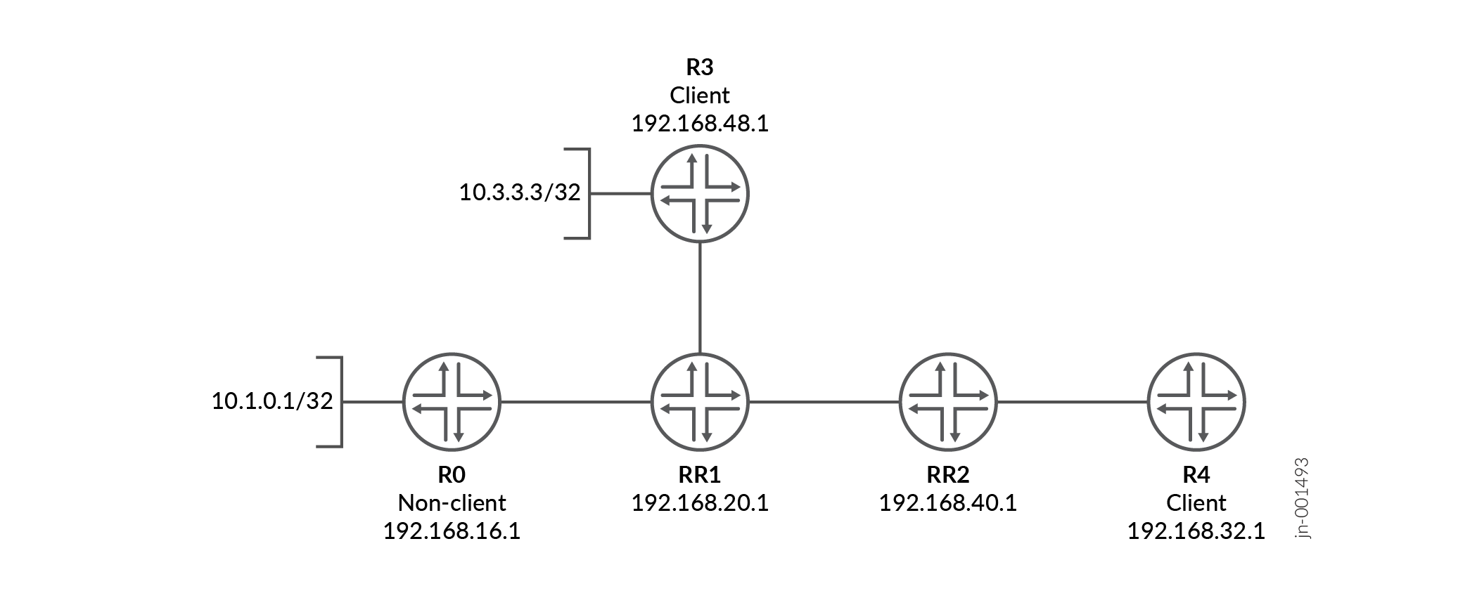
This example shows the BGP configuration on Device RR1 and Device RR2.
Configuration
Prerequisites
Before configuring BGP route reflectors in multiple clusters, ensure that IP reachability exists between all BGP peers. In this example, an interior gateway protocol (IGP), such as OSPF or IS-IS, provides reachability between the loopback interfaces used for IBGP sessions. Interface and IGP configuration is assumed to be in place and is not shown here.
Procedure
CLI Quick Configuration
To quickly configure this example, copy the following commands, paste them into a
text file, remove any line breaks, change any details necessary to match your
network configuration, and then copy and paste the commands into the CLI at the
[edit] hierarchy level.
Device RR1
set protocols bgp group RR1_client type internal
set protocols bgp group RR1_client local-address 192.168.20.1
set protocols bgp group RR1_client cluster 10.13.1.3
set protocols bgp group RR1_client neighbor 192.168.48.1
set protocols bgp group Non_client type internal
set protocols bgp group Non_client local-address 192.168.20.1
set protocols bgp group Non_client neighbor 192.168.16.1
set protocols bgp group RR1_to_RR2 type internal
set protocols bgp group RR1_to_RR2 local-address 192.168.20.1
set protocols bgp group RR1_to_RR2 cluster 10.12.1.2
set protocols bgp group RR1_to_RR2 neighbor 192.168.40.1
Device RR2
set protocols bgp group RR2_client type internal
set protocols bgp group RR2_client local-address 192.168.40.1
set protocols bgp group RR2_client cluster 10.24.2.4
set protocols bgp group RR2_client neighbor 192.168.32.1
set protocols bgp group RR2_to_RR1 type internal
set protocols bgp group RR2_to_RR1 local-address 192.168.40.1
set protocols bgp group RR2_to_RR1 neighbor 192.168.20.1
Configuring Device RR1
Step-by-Step Procedure
The following example requires you to navigate various levels in the configuration hierarchy. For information about navigating the CLI, see Using the CLI Editor in Configuration Mode in the Junos OS CLI User Guide.
To configure Device RR1:
-
Configure the peering relationship with Device R3.
[edit protocols bgp group RR1_client]
user@RR1# set type internal
user@RR1# set local-address 192.168.20.1
user@RR1# set cluster 10.13.1.3
user@RR1# set neighbor 192.168.48.1
-
Configure the peering relationship with Device R0.
[edit protocols bgp group Non_client]
user@RR1# set type internal
user@RR1# set local-address 192.168.20.1
user@RR1# set neighbor 192.168.16.1
-
Configure the peering relationship with Device RR2.
[edit protocols bgp group RR1_to_RR2]
user@RR1# set type internal
user@RR1# set local-address 192.168.20.1
user@RR1# set cluster 10.12.1.2
user@RR1# set neighbor 192.168.40.1
Results
From configuration mode, confirm your configuration by entering the show
protocols command. If the output does not display the intended
configuration, repeat the instructions in this example to correct the
configuration.
user@RR1# show protocols
bgp {
    group RR1_client {
        type internal;
        local-address 192.168.20.1;
        cluster 10.13.1.3;
        neighbor 192.168.48.1;
    }
    group Non_client {
        type internal;
        local-address 192.168.20.1;
        neighbor 192.168.16.1;
    }
    group RR1_to_RR2 {
        type internal;
        local-address 192.168.20.1;
        cluster 10.12.1.2;
        neighbor 192.168.40.1;
    }
}
If you are done configuring the device, enter commit from
configuration mode.
Configuring Device RR2
Step-by-Step Procedure
The following example requires you to navigate various levels in the configuration hierarchy. For information about navigating the CLI, see Using the CLI Editor in Configuration Mode in the Junos OS CLI User Guide.
To configure Device RR2:
-
Configure the peering relationship with Device R4.
[edit protocols bgp group RR2_client]
user@RR2# set type internal
user@RR2# set local-address 192.168.40.1
user@RR2# set cluster 10.24.2.4
user@RR2# set neighbor 192.168.32.1
-
Configure the peering relationship with Device RR1.
[edit protocols bgp group RR2_to_RR1]
user@RR2# set type internal
user@RR2# set local-address 192.168.40.1
user@RR2# set neighbor 192.168.20.1
Results
From configuration mode, confirm your configuration by entering the show
protocols command. If the output does not display the intended
configuration, repeat the instructions in this example to correct the
configuration.
user@RR2# show protocols
bgp {
    group RR2_client {
        type internal;
        local-address 192.168.40.1;
        cluster 10.24.2.4;
        neighbor 192.168.32.1;
    }
    group RR2_to_RR1 {
        type internal;
        local-address 192.168.40.1;
        neighbor 192.168.20.1;
    }
}
If you are done configuring the device, enter commit from
configuration mode.
Verification
Confirm that the configuration is working properly.
- Checking the Cluster ID Advertised for Route 10.3.3.3
- Checking the Cluster ID Advertised for Route 10.1.0.1
Checking the Cluster ID Advertised for Route 10.3.3.3
Purpose
Verify that BGP is running on configured interfaces and that the BGP session is established for each neighbor address.
Action
From operational mode, enter the show route advertising-protocol bgp
neighbor-address
command.
user@RR1> show route advertising-protocol bgp 192.168.40.1 active-path 10.3.3.3 extensive
inet.0: 61 destinations, 61 routes (60 active, 0 holddown, 1 hidden)
* 10.3.3.3/32 (1 entry, 1 announced)
BGP group RR1_to_RR2 type Internal
Nexthop: 192.168.48.1
Localpref: 100
AS path: [100] I
Cluster ID: 10.13.1.3
Originator ID: 192.168.48.1Meaning
The 10.3.3.3/32 route originates from the Device RR1’s client peer, Device R3. When this route is sent to RR1’s client, Device RR2, the route has the 10.13.1.3 cluster ID attached, which is the cluster ID for RR1-R3.
Checking the Cluster ID Advertised for Route 10.1.0.1
Purpose
Check the route advertisement from Device RR1 to Device RR2.
Action
From operational mode, enter the
show route advertising-protocol bgp
                                neighbor-address
command.
user@RR1> show route advertising-protocol bgp 192.168.40.1 active-path 10.1.0.1/32 extensive
inet.0: 61 destinations, 61 routes (60 active, 0 holddown, 1 hidden)
* 10.1.0.1/32 (1 entry, 1 announced)
 BGP group RR1_to_RR2 type Internal
     Nexthop: 192.168.16.1
     Localpref: 100
     AS path: [100] I
     Cluster ID: 10.12.1.2
     Originator ID: 192.168.16.1
Meaning
The 10.1.0.1/32 route originates from the Device RR1’s non-client peer, Device R0. When this route is sent to RR1’s client, Device RR2, the route has the 10.12.1.2 cluster ID attached, which is the cluster ID for RR1-RR2.
Device RR1 preserves the inbound cluster ID from Device RR2 when advertising to another client in a different cluster (Device R4).
Route Reflection at AS Border Routers
In most deployments, BGP route reflectors operate exclusively as internal BGP (IBGP) routers. However, in some network designs, a route reflector may also function as an autonomous system border router (ASBR) and maintain external BGP (EBGP) peering sessions.
When a Junos OS router performs both roles and receives a route from an EBGP peer, special
considerations apply if the router advertises that route to IBGP peers configured as route
reflector clients using the cluster option. In this case, Junos OS attaches
the ORIGINATOR_ID and CLUSTER_LIST path attributes when reflecting the route to IBGP
clients.
RFC 4456, which defines BGP route reflection, does not explicitly specify expected behavior for routes learned via EBGP and subsequently reflected to IBGP clients by a dual-role ASBR and route reflector. Junos OS applies route reflection attributes consistently in this scenario to prevent routing loops and to preserve deterministic path selection within the autonomous system.
When deploying route reflection on AS border routers, carefully consider routing policy, path selection, and failure scenarios to ensure that reflected routes do not introduce unintended routing behavior.
Change History Table
Feature support is determined by the platform and release you are using. Use Feature Explorer to determine if a feature is supported on your platform.
no-install statement eliminates interaction between the routing protocols daemon (rpd) and other components in the Junos system such as the kernel or the distributed firewall daemon (dfwd).