ON THIS PAGE
Egress Peer Traffic Engineering Using BGP Labeled Unicast Overview
Example: Configuring Egress Peer Traffic Engineering Using BGP Labeled Unicast
Segment Routing Traffic Engineering at BGP Ingress Peer Overview
Configuring Ingress Traffic Engineering with Segment Routing in a BGP Network
Enabling Traffic Statistics Collection for BGP Labeled Unicast
Overview of SRv6 Network Programming and Layer 3 Services over SRv6 in BGP
Example: Configuring Layer 3 Services over SRv6 in BGP Networks
BGP Egress Traffic Engineering
Egress Peer Traffic Engineering Using BGP Labeled Unicast Overview
In a data center environment, which mimics an ISP BGP-free core, the ingress nodes tunnel the service traffic to an egress router that is also the AS boundary router. Egress peer traffic engineering allows a central controller to instruct an ingress router in a domain to direct the traffic towards a specific egress router and a specific external interface to reach a particular destination out of the network. Egress peer traffic engineering allows for the selection of the best advertised egress route and mapping of the selected best route to a specific egress point. In case of load balancing at the ingress, this feature ensures optimum utilization of the advertised egress routes.
The ingress router controls the egress peer selection by pushing
the corresponding MPLS label on an MPLS label stack for traffic engineering
the links between ASs. AS boundary routers automatically install the
IPv4 or IPv6 peer /32 or /128 route to an established external BGP
peer that is configured with the egress traffic engineering feature
into the inet.3 forwarding table. These routes have a forwarding
action of pop and forward, that is, remove the label, and forward
the packet to the external BGP peer.
AS boundary routers advertise the IPv4 or IPv6 peer /32 or/128 route to the ingress BGP peers with self IPv4 next hop. Ingress BGP peers have a transport tunnel, such as MPLS LDP to reach the AS boundary router. Thus, all the network exit points are advertised to the MPLS network cloud as labeled BGP routes. The AS boundary routers advertise service routes with these exit points as protocol next hops. The AS boundary routers readvertise the service routes from the external BGP peers towards the core without altering the next-hop addresses. However, the ingress routers resolve the protocol next hop in the service routes to map to the correct transport tunnel to the egress peer interface. Thus, the ingress routers map traffic for a specific service prefix to a specific egress router or load-balance the traffic across available egress devices. This feature allows the ingress router to direct the service traffic towards a specific egress peer.
In addition to egress peer traffic engineering, this feature
provides MPLS fast reroute (FRR) for each egress device it advertises
to the MPLS IPv4 network cloud. You can configure one or more backup
devices for the primary egress AS boundary router. Junos OS automatically
installs the backup path in addition to the primary path into the
MPLS forwarding table of the established egress BGP peer that has
egress peer traffic engineering configured. The AS boundary router
switches to the backup path when the primary link fails and provides
MPLS FRR . The specified backup path is through another directly connected
external BGP peer or a remote next hop. You can also configure a backup
path using ip lookup in an inet6.0 table. However, the remote-nexthop and ip-forward backup options are
mutually exclusive.
See Also
Configuring Egress Peer Traffic Engineering by Using BGP Labeled Unicast and Enabling MPLS Fast Reroute
Egress peer traffic engineering (TE) allows a central controller to instruct an ingress router in a domain to direct traffic towards a specific egress router and a specific external interface to reach a particular destination out of the network for optimum utilization of the advertised egress routes during load balancing.
BGP segregates the network into layers, such as transport and service layers. The BGP labeled unicasts form the transport layer, and the BGP unicast subsequent address family identifier (SAFI) add path routes form the service layer. The AS boundary router triggers the transport layer BGP labeled unicast label-switched paths (LSPs) that provide a route to the egress peers. The service layer add path routes use these egress peers as protocol next hop. The AS boundary routers optionally provide MPLS fast reroute (FRR) at the transport layer, which must be utilized because service layer peering issues are common. Therefore, you can specify one or more backup devices for the primary egress AS boundary router. Junos OS automatically installs the backup path in addition to the primary path into the MPLS forwarding table of the established egress BGP peer that has egress peer TE configured. The backup path provides FRR when the primary link fails.
See Also
Example: Configuring Egress Peer Traffic Engineering Using BGP Labeled Unicast
This example shows how to configure egress peer traffic engineering using BGP labeled unicast. Egress peer traffic engineering allows a central controller to instruct an ingress router in a domain to direct traffic towards a specific egress router and a specific external interface to reach a particular destination out of the network. In case of load balancing at the ingress, this feature ensures optimum utilization of the advertised egress routes.
Requirements
This example uses the following hardware and software components:
-
Nine MX Series routers
-
Junos OS Release 14.2R4 or later
Overview
Beginning with Junos OS Release 14.2R4, you can enable traffic engineering (TE) of service traffic, such as MPLS LSP traffic between autonomous systems (ASs) using BGP labeled unicast for optimum utilization of the advertised egress routes during load balancing.
Configure egress peer TE to direct core service traffic such as MPLS RSVP to a specific egress BGP peer. The ingress BGP peer can traffic-engineer the core inet unicast and inet6 unicast service traffic using BGP labeled unicast towards a specific egress BGP peer.
You cannot configure egress peer TE for external BGP multihop peers. The ARP
routes in inet.3 are installed for peer /32 and /128 routes
only.
Topology
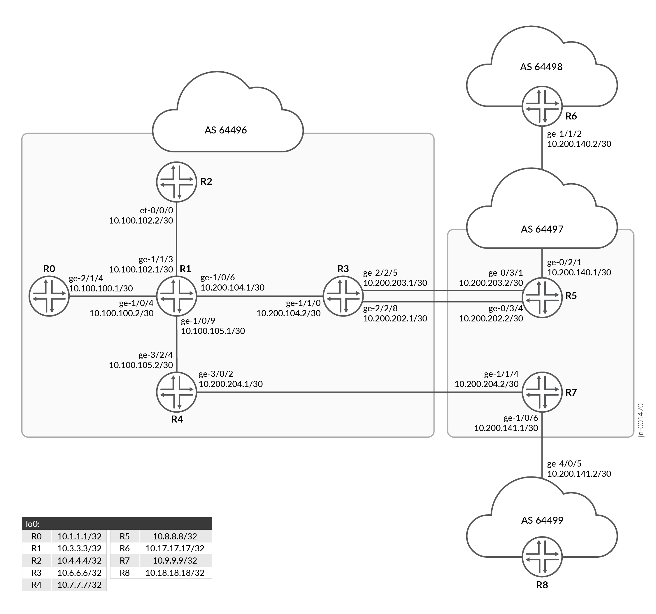
Overview shows the sample topology. Router R3 and Router R4 are the AS boundary routers. Egress peer TE is enabled on R3. The ingress Router R0 directs traffic destined to a remote network to Router R3, which has egress peer TE enabled.
Configuration
CLI Quick Configuration
To quickly configure this example, copy the following commands, paste them into a
text file, remove any line breaks, change any details necessary to match your
network configuration, copy and paste the commands into the CLI at the
[edit] hierarchy level, and then enter
commit from configuration mode.
Router R0
set interfaces ge-2/1/4 unit 0 description "CONNECTED TO R1"
set interfaces ge-2/1/4 unit 0 family inet address 10.100.100.1/30
set interfaces ge-2/1/4 unit 0 family mpls
set interfaces lo0 unit 0 family inet address 10.1.1.1/32
set policy-options prefix-list server_v4_prefix 10.1.1.1/32
set policy-options policy-statement exp-svr-pre term 1 from prefix-list server_v4_prefix
set policy-options policy-statement exp-svr-pre term 1 then accept
set policy-options policy-statement nhs then next-hop self
set routing-options router-id 10.1.1.1
set routing-options autonomous-system 64496
set protocols bgp group RR-1-2 type internal
set protocols bgp group RR-1-2 local-address 10.1.1.1
set protocols bgp group RR-1-2 family inet labeled-unicast rib inet.3
set protocols bgp group RR-1-2 family inet unicast add-path receive
set protocols bgp group RR-1-2 family inet unicast add-path send path-count 6
set protocols bgp group RR-1-2 export exp-svr-pre
set protocols bgp group RR-1-2 export nhs
set protocols bgp group RR-1-2 neighbor 10.4.4.4
set protocols bgp group R0RT0 type external
set protocols bgp group R0RT0 family inet unicast
set protocols bgp group R0RT0 peer-as 64499
set protocols bgp group R0RT0 neighbor 10.1.1.2
set protocols ldp interface all
set protocols ldp interface fxp0.0 disable
set protocols mpls no-cspf
set protocols mpls label-switched-path to_asbr1_r3 to 10.6.6.6
set protocols mpls label-switched-path to_asbr2_r4 to 10.7.7.7
set protocols mpls interface all
set protocols mpls interface fxp0.0 disable
set protocols ospf area 0.0.0.0 interface ge-2/1/4.0
set protocols ospf area 0.0.0.0 interface fxp0.0 disable
set protocols ospf area 0.0.0.0 interface lo0.0 passive
set protocols rsvp interface all
set protocols rsvp interface fxp0.0 disable
Router R1
set interfaces ge-1/0/4 unit 0 description "CONNECTED TO R0"
set interfaces ge-1/0/4 unit 0 family inet address 00.100.100.2/30
set interfaces ge-1/0/4 unit 0 family mpls
set interfaces ge-1/0/6 unit 0 description "CONNECTED TO R3"
set interfaces ge-1/0/6 unit 0 family inet address 10.100.104.1/30
set interfaces ge-1/0/6 unit 0 family mpls
set interfaces ge-1/0/9 unit 0 description "CONNECTED TO R4"
set interfaces ge-1/0/9 unit 0 family inet address 100.100.105.1/30
set interfaces ge-1/0/9 unit 0 family mpls
set interfaces ge-1/1/3 unit 0 description "CONNECTED TO R2"
set interfaces ge-1/1/3 unit 0 family inet address 10.100.102.1/30
set interfaces ge-1/1/3 unit 0 family mpls
set interfaces lo0 unit 0 family inet address 10.3.3.3/32
set routing-options router-id 10.3.3.3
set routing-options autonomous-system 64496
set protocols rsvp interface all
set protocols rsvp interface fxp0.0 disable
set protocols mpls interface all
set protocols mpls interface fxp0.0 disable
set protocols ospf area 0.0.0.0 interface all
set protocols ospf area 0.0.0.0 interface fxp0.0 disable
set protocols ospf area 0.0.0.0 interface lo0.0 passive
set protocols ldp interface all
set protocols ldp interface fxp0.0 disable
Router R2
set interfaces et-0/0/0 unit 0 description "CONNECTED TO R1"
set interfaces et-0/0/0 unit 0 family inet address 10.100.102.2/30
set interfaces et-0/0/0 unit 0 family mpls
set interfaces lo0 unit 0 family inet address 10.4.4.4/32
set routing-options router-id 10.4.4.4
set routing-options autonomous-system 64496
set protocols rsvp interface all
set protocols rsvp interface fxp0.0 disable
set protocols mpls interface all
set protocols mpls interface fxp0.0 disable
set protocols bgp group Client type internal
set protocols bgp group Client local-address 10.4.4.4
set protocols bgp group Client advertise-inactive
set protocols bgp group Client family inet unicast add-path receive
set protocols bgp group Client family inet unicast add-path send path-count 6
set protocols bgp group Client family inet labeled-unicast rib inet.3
set protocols bgp group Client cluster 10.4.4.4
set protocols bgp group Client neighbor 10.1.1.1
set protocols bgp group Client neighbor 10.6.6.6
set protocols bgp group Client neighbor 10.7.7.7
set protocols ospf area 0.0.0.0 interface et-0/0/0.0
set protocols ospf area 0.0.0.0 interface fxp0.0 disable
set protocols ospf area 0.0.0.0 interface lo0.0 passive
set protocols ldp interface all
set protocols ldp interface fxp0.0 disable
Router R3
set interfaces ge-1/1/0 unit 0 description "CONNECTED TO R1"
set interfaces ge-1/1/0 unit 0 family inet address 10.100.104.2/30
set interfaces ge-1/1/0 unit 0 family mpls
set interfaces ge-2/2/5 unit 0 description "CONNECTED TO R5"
set interfaces ge-2/2/5 unit 0 family inet address 10.200.203.1/28
set interfaces ge-2/2/8 unit 0 description "CONNECTED TO R5"
set interfaces ge-2/2/8 unit 0 family inet address 10.200.202.1/30
set interfaces lo0 unit 0 family inet address 10.6.6.6/32
set policy-options prefix-list server_v4_pre 10.1.1.1/32
set policy-options policy-statement exp-arp-to-rrs term 1 from protocol arp
set policy-options policy-statement exp-arp-to-rrs term 1 from rib inet.3
set policy-options policy-statement exp-arp-to-rrs term 1 then next-hop self
set policy-options policy-statement exp-arp-to-rrs term 1 then accept
set policy-options policy-statement exp-arp-to-rrs term 3 from protocol bgp
set policy-options policy-statement exp-arp-to-rrs term 3 then accept
set policy-options policy-statement exp-arp-to-rrs term 4 then reject
set policy-options policy-statement pplb then load-balance per-packet
set routing-options router-id 10.6.6.6
set routing-options autonomous-system 64496
set routing-options forwarding-table export pplb
set protocols bgp group RR-1-2 type internal
set protocols bgp group RR-1-2 local-address 10.6.6.6
set protocols bgp group RR-1-2 family inet labeled-unicast rib inet.3
set protocols bgp group RR-1-2 family inet unicast add-path receive
set protocols bgp group RR-1-2 family inet unicast add-path send path-count 6
set protocols bgp group RR-1-2 export exp-arp-to-rrs
set protocols bgp group RR-1-2 neighbor 10.4.4.4
set protocols bgp group Peer1-lan-1 type external
set protocols bgp group Peer1-lan-1 family inet unicast
set protocols bgp group Peer1-lan-1 peer-as 64497
set protocols bgp group Peer1-lan-1 neighbor 10.200.202.2 egress-te
set protocols bgp group Peer1-lan-1 neighbor 10.200.203.2 egress-te
set protocols bgp log-updown
set protocols ldp interface all
set protocols ldp interface fxp0.0 disable
set protocols mpls interface all
set protocols mpls interface fxp0.0 disable
set protocols ospf area 0.0.0.0 interface ge-1/1/0.0
set protocols ospf area 0.0.0.0 interface fxp0.0 disable
set protocols ospf area 0.0.0.0 interface lo0.0 passive
set protocols rsvp interface all
set protocols rsvp interface fxp0.0 disable
Router R4
set interfaces ge-3/0/2 vlan-tagging
set interfaces ge-3/0/2 unit 0 description "CONNECTED TO R7"
set interfaces ge-3/0/2 unit 0 vlan-id 1
set interfaces ge-3/0/2 unit 0 family inet address 10.200.204.1/24
set interfaces ge-3/0/2 unit 0 family mpls
set interfaces ge-3/0/2 unit 1 vlan-id 2
set interfaces ge-3/2/4 unit 0 description "CONNECTED TO R1"
set interfaces ge-3/2/4 unit 0 family inet address 10.100.105.2/30
set interfaces ge-3/2/4 unit 0 family mpls
set interfaces lo0 unit 0 family inet address 10.7.7.7/32
set policy-options prefix-list server_v4_pre 10.1.1.1/32
set policy-options policy-statement exp-arp-to-rrs term 1 from protocol arp
set policy-options policy-statement exp-arp-to-rrs term 1 from rib inet.3
set policy-options policy-statement exp-arp-to-rrs term 1 then next-hop self
set policy-options policy-statement exp-arp-to-rrs term 1 then accept
set policy-options policy-statement exp-arp-to-rrs term 3 from protocol bgp
set policy-options policy-statement exp-arp-to-rrs term 3 then accept
set policy-options policy-statement exp-arp-to-rrs term 4 then reject
set policy-options policy-statement pplb then load-balance per-packet
set routing-options router-id 10.7.7.7
set routing-options autonomous-system 64496
set routing-options forwarding-table export pplb
set protocols bgp group RR-1-2 type internal
set protocols bgp group RR-1-2 local-address 10.7.7.7
set protocols bgp group RR-1-2 family inet labeled-unicast rib inet.3
set protocols bgp group RR-1-2 family inet unicast add-path receive
set protocols bgp group RR-1-2 family inet unicast add-path send path-count 6
set protocols bgp group RR-1-2 export exp-arp-to-rrs
set protocols bgp group RR-1-2 neighbor 10.4.4.4
set protocols bgp group Peer5-6-lan type external
set protocols bgp group Peer5-6-lan family inet unicast
set protocols bgp group Peer5-6-lan peer-as 64497
set protocols ldp interface all
set protocols ldp interface fxp0.0 disable
set protocols mpls interface all
set protocols mpls interface fxp0.0 disable
set protocols ospf area 0.0.0.0 interface ge-3/2/4.0
set protocols ospf area 0.0.0.0 interface fxp0.0 disable
set protocols ospf area 0.0.0.0 interface lo0.0 passive
set protocols rsvp interface all
set protocols rsvp interface fxp0.0 disable
Router R5
set interfaces ge-0/2/1 unit 0 description "CONNECTED TO R6"
set interfaces ge-0/2/1 unit 0 family inet address 10.100.140.1/30
set interfaces ge-0/3/1 unit 0 description "CONNECTED TO R3"
set interfaces ge-0/3/1 unit 0 family inet address 10.200.203.2/28
set interfaces ge-0/3/4 unit 0 description "CONNECTED TO R3"
set interfaces ge-0/3/4 unit 0 family inet address 10.200.202.2/30
set interfaces lo0 unit 0 family inet address 10.8.8.8/32
set policy-options policy-statement exp-lo0 term 1 from interface lo0.0
set policy-options policy-statement exp-lo0 term 1 then accept
set routing-options router-id 10.8.8.8
set routing-options autonomous-system 64497
set protocols bgp group Peer1-lan-1 type external
set protocols bgp group Peer1-lan-1 family inet unicast
set protocols bgp group Peer1-lan-1 export exp-lo0
set protocols bgp group Peer1-lan-1 peer-as 64496
set protocols bgp group Peer1-lan-1 neighbor 10.200.202.1
set protocols bgp group Peer1-lan-1 neighbor 10.200.203.1
set protocols bgp group Peer1-H1 type external
set protocols bgp group Peer1-H1 family inet unicast
set protocols bgp group Peer1-H1 neighbor 10.100.140.2 peer-as 64498
Router R6
set interfaces ge-1/1/2 unit 0 description "CONNECTED TO R5"
set interfaces ge-1/1/2 unit 0 family inet address 10.100.140.2/30
set interfaces lo0 unit 0 family inet address 10.17.17.1/32
set policy-options policy-statement exp-lo0 term 1 from interface lo0.0
set policy-options policy-statement exp-lo0 term 1 then accept
set policy-options policy-statement exp-lo0 term 2 from protocol direct
set policy-options policy-statement exp-lo0 term 2 from protocol local
set policy-options policy-statement exp-lo0 term 2 then accept
set routing-options router-id 10.17.17.1
set routing-options autonomous-system 64498
set protocols bgp group H1-Peer1 type external
set protocols bgp group H1-Peer1 family inet unicast
set protocols bgp group H1-Peer1 export exp-lo0
set protocols bgp group H1-Peer1 neighbor 10.100.140.1 peer-as 64497
Router R7
set interfaces ge-1/0/6 unit 0 description "CONNECTED TO R8"
set interfaces ge-1/0/6 unit 0 family inet address 10.100.141.1/30
set interfaces ge-1/1/4 vlan-tagging
set interfaces ge-1/1/4 unit 0 description "CONNECTED TO R4"
set interfaces ge-1/1/4 unit 0 vlan-id 1
set interfaces ge-1/1/4 unit 0 family inet address 10.200.204.2/24
set interfaces lo0 unit 0 family inet address 10.9.9.9/32
set policy-options policy-statement exp-lo0 term 1 from interface lo0.0
set policy-options policy-statement exp-lo0 term 1 then accept
set routing-options router-id 10.9.9.9
set routing-options autonomous-system 64497
set protocols bgp group Peer1-lan-1 type external
set protocols bgp group Peer1-lan-1 family inet unicast
set protocols bgp group Peer1-lan-1 export exp-lo0
set protocols bgp group Peer1-lan-1 peer-as 64496
set protocols bgp group Peer1-lan-1 neighbor 10.200.204.1
set protocols bgp group Peer2-H2 type external
set protocols bgp group Peer2-H2 family inet unicast
set protocols bgp group Peer2-H2 neighbor 10.100.141.2 peer-as 64499
Router R8
set interfaces ge-4/0/5 unit 0 description "CONNECTED TO R7"
set interfaces ge-4/0/5 unit 0 family inet address 10.100.141.2/30
set interfaces lo0 unit 0 family inet address 10.18.18.1/32
set policy-options policy-statement exp-lo0 term 1 from interface lo0.0
set policy-options policy-statement exp-lo0 term 1 then accept
set policy-options policy-statement exp-lo0 term 2 then reject
set routing-options router-id 10.18.18.1
set routing-options autonomous-system 64499
set protocols bgp group H2-Peer2 type external
set protocols bgp group H2-Peer2 family inet unicast
set protocols bgp group H2-Peer2 export exp-lo0
set protocols bgp group H2-Peer2 neighbor 10.100.141.1 peer-as 64497
set protocols bgp group R8RT0 type external
set protocols bgp group R8RT0 family inet unicast
set protocols bgp group R8RT0 peer-as 64496
set protocols bgp group R8RT0 neighbor 10.1.1.2
Configuring Router R3
Step-by-Step Procedure
The following example requires that you navigate various levels in the configuration hierarchy. For information about navigating the CLI, see Using the CLI Editor in Configuration Mode in the CLI User Guide.
To configure Router R3:
Repeat this procedure for other routers after modifying the appropriate interface names, addresses, and other parameters.
-
Configure the interfaces with IPv4 addresses.
[edit interfaces]
user@R3#set ge-1/1/0 unit 0 description "CONNECTED TO R1"
user@R3#set ge-1/1/0 unit 0 family inet address 10.100.104.2/30
user@R3#set ge-1/1/0 unit 0 family mpls
user@R3#set ge-2/2/5 unit 0 description "CONNECTED TO R5"
user@R3#set ge-2/2/5 unit 0 family inet address 10.200.203.1/28
user@R3#set ge-2/2/8 unit 0 description "CONNECTED TO R5"
user@R3#set ge-2/2/8 unit 0 family inet address 10.200.202.1/30
-
Configure the loopback addresses.
[edit interfaces]
user@R3#set lo0 unit 0 family inet address 10.6.6.6/32
-
Configure the router ID and autonomous system (AS) number.
[edit routing-options]
user@R3# set router-id 10.6.6.6
user@R3# set autonomous-system 64496
user@R3#set forwarding-table export pplb
-
Configure the RSVP protocol for all interfaces except the management interface.
[edit protocols]
user@R3# set rsvp interface all
user@R3# set rsvp interface fxp0.0 disable
-
Configure the MPLS protocol for all interfaces except the management interface.
[edit protocols]

user@R3# set mpls interface all
user@R3# set mpls interface fxp0.0 disable
-
Configure IBGP peering sessions on the core-facing interface.
[edit protocols]
user@R3# set bgp log-updown
user@R3# set bgp group RR-1-2 type internal
user@R3# set bgp group RR-1-2 local-address 10.6.6.6
user@R3# set bgp group RR-1-2 family inet unicast add-path receive
user@R3# set bgp group RR-1-2 family inet unicast add-path send path-count 6
user@R3# set bgp group RR-1-2 family inet labeled-unicast rib inet.3

user@R3#set bgp group RR-1-2 export exp-arp-to-rrs
user@R3# set bgp group RR-1-2 neighbor 10.4.4.4
-
Configure EBGP peering sessions on interfaces facing external edge routers.
[edit protocols]
user@R3# set bgp group Peer1-lan-1 type external
user@R3# set bgp group Peer1-lan-1 family inet unicast
user@R3# set bgp group Peer1-lan-1 peer-as 64497
-
Enable egress peer traffic engineering for external BGP group Peer1-lan-1.
[edit protocols]
user@R3# set bgp group Peer1-lan-1 neighbor 10.200.202.2 egress-te
user@R3# set bgp group Peer1-lan-1 neighbor 10.200.203.2 egress-te
-
Configure the OSPF protocol as the IGP.
[edit protocols]
user@R3# set ospf area 0.0.0.0 interface ge-1/1/0.0
user@R3# set ospf area 0.0.0.0 interface fxp0.0 disable
user@R3# set ospf area 0.0.0.0 interface lo0.0 passive
user@R3# set ldp interface all
user@R3# set ldp interface fxp0.0 disable
-
Define a policy for exporting ARP routes to route reflectors.
[edit policy-options]
user@R3# set policy-statement exp-arp-to-rrs term 1 from protocol arp
user@R3# set policy-statement exp-arp-to-rrs term 1 from rib inet.3
user@R3# set policy-statement exp-arp-to-rrs term 1 then next-hop self
user@R3# set policy-statement exp-arp-to-rrs term 1 then accept
user@R3# set policy-statement exp-arp-to-rrs term 3 from protocol bgp
user@R3# set policy-statement exp-arp-to-rrs term 3 then accept
user@R3# set policy-statement exp-arp-to-rrs term 4 then reject
-
Apply the policy exp-arp-to-rrs for exporting ARP routes to route reflectors to the external BGP group.
[edit protocols]
user@R3# set bgp group RR-1-2 export exp-arp-to-rrs
-
Define prefix lists with IPv4 routes.
[edit policy-options]
user@R3# set prefix-list server_v4_pre 10.1.1.1/32
-
Define a per-packet load-balancing policy.
[edit policy-options]
user@R3# set policy-statement pplb then load-balance per-packet
-
Apply the per-packet load-balancing policy.
[edit routing-options]
user@R3# set forwarding-table export pplb
Results
From configuration mode, confirm your configuration by entering the show interfaces, show protocols, show routing-options, and show policy-options commands. If the output does not display the intended configuration, repeat the instructions in this example to correct the configuration.
user@R3# show interfaces
ge-1/1/0 {
    unit 0 {
        description "CONNECTED TO R1";
        family inet {
            address 10.100.104.2/30;
        }
        family mpls;
    }
}
ge-2/2/5 {
    unit 0 {
        description "CONNECTED TO R5";
        family inet {
            address 10.200.203.1/28;
        }
    }
}
ge-2/2/8 {
    unit 0 {
        description "CONNECTED TO R5";
        family inet {
            address 10.200.202.1/30;
        }
    }
}
lo0 {
    unit 0 {
        family inet {
            address 10.6.6.6/32;
        }
    }
}
user@R3# show protocols
bgp {
    group RR-1-2 {
        type internal;
        local-address 10.6.6.6;
        family inet {
            labeled-unicast {
                rib {
                    inet.3;
                }
            }
            unicast {
                add-path {
                    receive;
                    send {
                        path-count 6;
                    }
                }
            }
        }
        export exp-arp-to-rrs;
        neighbor 10.4.4.4;
    }
    group Peer1-lan-1 {
        type external;
        family inet {
            unicast;
        }
        peer-as 64497;
        neighbor 10.200.202.2 {
            egress-te;
        }
        neighbor 10.200.203.2 {
            egress-te;
        }
    }
    log-updown;
}
ldp {
    interface all;
    interface fxp0.0 {
        disable;
    }
}
mpls {
    interface all;
    interface fxp0.0 {
        disable;
    }
}
ospf {
    area 0.0.0.0 {
        interface ge-1/1/0.0;
        interface fxp0.0 {
            disable;
        }
        interface lo0.0 {
            passive;
        }
    }
}
rsvp {
    interface all;
    interface fxp0.0 {
        disable;
    }
}[edit]
user@R3# show routing-options
router-id 10.6.6.6;
autonomous-system 64496;
forwarding-table {
export pplb;
}
user@R3# show policy-options
prefix-list server_v4_pre {
    10.1.1.1/32;
}
policy-statement exp-arp-to-rrs {
    term 1 {
        from {
            protocol arp;
            rib inet.3;
        }
        then {
            next-hop self;
            accept;
        }
    }
    term 3 {
        from protocol bgp;
        then accept;
    }
    term 4 {
        then reject;
    }
}
policy-statement pplb {
    then {
        load-balance per-packet;
    }
}
Verification
Confirm that the configuration is working properly.
- Identifying the Label and the Protocol Next Hop
- Verifying the Path of Packet with Label 299888
- Verifying That Egress Peer Traffic Engineering Is Enabled on Router R3
Identifying the Label and the Protocol Next Hop
Purpose
Get the label number of the packet transported from R0 to R6 and the next hop from the routing table for route 10.17.17.2.
Action
From operational mode, run the show route 10.17.17.2 extensive active-path command on Router R0.
user@R0> show route 10.17.17.2 extensive active-path
inet.0: 262 destinations, 516 routes (261 active, 0 holddown, 1 hidden)
10.17.17.1/32 (3 entries, 1 announced)
TSI:
KRT in-kernel 10.17.17.1/32 -> {indirect(1048576)}
Page 0 idx 0, (group R0RT0 type External) Type 1 val 0x9a87fe0 (adv_entry)
   Advertised metrics:
     Nexthop: Self
     AS path: [65100] 1 65010 I
     Communities:
Path 10.17.17.1 from 10.4.4.4 Vector len 4.  Val: 0
        *BGP    Preference: 170/-101
                Next hop type: Indirect
                Address: 0x97724a0
                Next-hop reference count: 339
                Source: 10.4.4.4
                Next hop type: Router, Next hop index: 624
                Next hop: 10.100.100.2 via ge-2/1/4.0, selected
                Label-switched-path to_asbr1_r3
                Label operation: Push 299888, Push 300128(top)
                Label TTL action: prop-ttl, prop-ttl(top)
                Load balance label: Label 299888: None; Label 300128: None;
                Session Id: 0x145
                Protocol next hop: 10.200.201.2
                Indirect next hop: 0x9a4c550 1048576 INH Session ID: 0x148
                State: <Active Int Ext>
                Local AS:   65100 Peer AS:   65100
							  Age: 1:33       Metric2: 2
                Validation State: unverified
                Task: BGP_100.10.4.4.4+179
                Announcement bits (3): 0-KRT 5-BGP_RT_Background 6-Resolve tree 2
                AS path: 1 10 I (Originator)
                Cluster list:  10.4.4.4
                Originator ID: 10.6.6.6
                Accepted
                Localpref: 100
                Router ID: 10.4.4.4
                Addpath Path ID: 1
                Indirect next hops: 1
                         Protocol next hop: 10.200.202.2 Metric: 2
                         Indirect next hop: 0x9a4c550 1048576 INH Session ID: 0x148
                         Indirect path forwarding next hops: 1
                                 Next hop type: Router
                                 Next hop: 10.100.100.2 via ge-2/1/4.0
                                 Session Id: 0x145
                         10.200.201.2/32 Originating RIB: inet.3
                           Metric: 2                       Node path count: 1
                           Indirect nexthops: 1
                                 Protocol Nexthop: 10.6.6.6 Metric: 2 Push 299888
                                 Indirect nexthop: 0x9a4c220 - INH Session ID: 0x0                               Indirect path forwarding nexthops: 1                                                                       Nexthop: 100.100.100.2 via ge-2/1/4.0
Meaning
Both the packet label 299888 and the next hop 10.200.202.2 are displayed in the output.
Verifying the Path of Packet with Label 299888
Purpose
Trace the path of the label 299888 and verify that the VPN entry is present in the mpls.0 routing table.
Action
user@R3> show route table mpls.0 protocol vpn active-path label 299888 detail mpls.0: 17 destinations, 17 routes (17 active, 0 holddown, 0 hidden)523440(1 entry, 1 announced)*VPNPreference: 170 Next hop type: Router, Next hop index: 640 Address: 0xecfa130 Next-hop reference count: 2Next hop: 10.200.202.2via ge-2/2/8.0, selectedLabel operation: PopLoad balance label: None; Session Id: 0x16f State: <Active Int Ext> Local AS: 64496 Age: 3:49:16 Validation State: unverified Task: BGP_RT_Background Announcement bits (1): 1-KRT AS path: I Ref Cnt: 1
Meaning
The label 299888 with VPN entry and next hop 10.200.202.2 is present in the mpls.0 routing table.
Verifying That Egress Peer Traffic Engineering Is Enabled on Router R3
Purpose
Verify that the egress peer traffic engineering is configured on Router R3.
Action
user@R3> show route protocol arp detail match-prefix 10.200.202.2
inet.0: 263 destinations, 514 routes (262 active, 0 holddown, 1 hidden)

inet.3: 10 destinations, 10 routes (10 active, 0 holddown, 0 hidden)
10.200.201.2/32 (1 entry, 1 announced)
        *ARP    Preference: 170
                Next hop type: Router
                Address: 0xecf91e0
                Next-hop reference count: 5
                Next hop: 10.200.202.2 via ge-2/2/8.0, selected
                Label operation: Pop
                Load balance label: None;
                Session Id: 0x0
                State: <Active Int Ext>
							  Local AS:   64496
								Age: 3:52:52
								Validation State: unverified
								Task: BgpEgressPeeringTE
								Announcement bits (3): 2-Resolve tree 1 3-BGP_RT_Background 4-Resolve tree 2
Meaning
The output indicates that BGP egress peer traffic engineering is enabled on Router R3.
BGP Deterministic Path Forwarding in a CLOS Network
- BGP Deterministic Path Forwarding Overview
- Configure BGP Deterministic Path Forwarding in a CLOS Network
BGP Deterministic Path Forwarding Overview
BGP deterministic path forwarding (DPF) divides a physical fabric into multiple logical fabrics, where different flows are mapped to different logical fabrics to serve the requirements of the flows. Single-hop EBGP's best effort service might not meet all data center flow requirements, especially for drop and latency-sensitive AI-ML flows. BGP DPF selects a path based on the specified logical fabric to ensure optimum link utilization.
BGP DPF is a lightweight traffic engineering solution for data center IP fabrics. Data centers usually use single-hop EBGP for IPv4 and IPv6 routing. This is a simple and scalable hop-by-hop EBGP routing that provides a single best effort service for all traffic flows. BGP DPF divides a physical fabric into multiple logical fabrics. This allows both IPv4, and IPv6 traffic to be mapped to different logical fabrics. You can use separate logical fabrics for load balancing across links based on available bandwidth, and with different service level agreements (SLA). You can configure DPF to map flows to multiple logical fabrics to avoid fate sharing.
BGP DPF colors the single-hop EBGP session on each link with a fabric color. For example, if a link belongs to the red fabric, the EBGP session over the link is assigned a red BGP color community. A single-hop EBGP neighbor can be assigned a color at the global, group or neighbor level. A route with no color community assigned can be advertised over any colored or uncolored EBGP sessions.
-
If there is a color mismatch on the receiver side, the receiver marks the route as hidden.
-
All colored routes can be advertised over an uncolored BGP neighbor. To allow certain routes over only certain colors, do not have a mix of uncolored and colored fabrics.
-
You can advertise uncolored routes over all colored fabrics. To advertise matching colored routes over a colored fabric, do not have uncolored routes, except for those carrying light control traffic only.
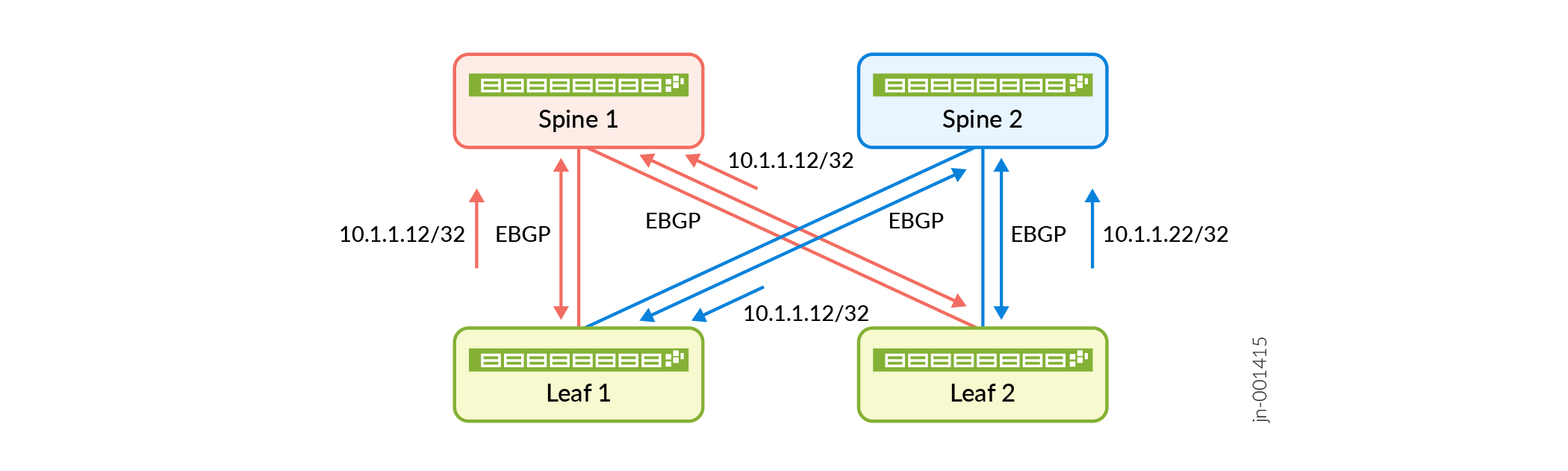
In Figure 2, Spine1 and Spine 2 are connected to leaf 1 and leaf 2 devices with multiple connections. BGP DPF colors the single-hop EBGP session on each link with a fabric color. Spine 1 belongs to the red fabric, the EBGP sessions over the red link are also colored red. Spine 2 belongs to the blue fabric, the EBGP sessions over the link are also colored blue. BGP advertises IP routes over the EBGP session based on color matching. BGP advertises a route over a red EBGP session if it only has the red color community or no color community. BGP advertises a route over a blue EBGP session if it only has the blue color community or no color community.
Benefits of BGP DPF
-
A lightweight traffic engineering solution for IP fabrics.
-
Correlation of underlay with overlay that isolates large elephant flows from small mice flows.
fabric-color configuration. However, we still support
these features for uncolored routes.Configure BGP Deterministic Path Forwarding in a CLOS Network
Segment Routing Traffic Engineering at BGP Ingress Peer Overview
This feature enables BGP to support a segment routing policy for traffic engineering at ingress routers. The controller can specify a segment routing policy consisting of multiple paths to steer labeled or IP traffic. The segment routing policy adds an ordered list of segments to the header of a packet for traffic steering. BGP installs the candidate routes of the segment routing policy into routing tables bgp.inetcolor.0 or bgp.inet6color.0. BGP selects one route from the candidate routes for a particular segment routing traffic engineering policy, and installs it in the new routing tables junos-rti-tc-<color>.inet.0 or junos-rti-tc-<color>.inet6.0. This feature supports both statically configured as well as BGP-installed segment routing traffic engineering policies in the forwarding table at ingress routers.
- Understanding Segment Routing Policies
- BGP’s Role in Route Selection from a Segment Routing Policy
- Statically Configured Segment Routing Policies
- Supported and Unsupported Features
Understanding Segment Routing Policies
In segment routing the controller allows the ingress nodes in a core network to steer traffic through explicit paths while eliminating the state for the explicit paths in intermediate nodes. An ordered list of segments associated with the segment routing policy is added to the header of a data packet. These segment lists or lists of segment identifiers (SIDs) represent paths in the network, which are the best candidate paths selected from multiple candidate paths learned from various sources. An ordered list of segments is encoded as a stack of labels. This feature enables steering a packet toward a specific path depending on the network or customer requirements. The traffic can be labeled or IP traffic and is steered with a label swap or a destination-based lookup toward these segment routing traffic engineering paths. You can configure static policies at ingress routers to steer traffic even when the link to the controller fails. Static segment routing policies are useful to ensure traffic steering when the controller is down or unreachable.
BGP’s Role in Route Selection from a Segment Routing Policy
When BGP receives an update for segment routing traffic engineering subsequent address family identifier (SAFI) from the controller, BGP performs some basic checks and validation on these updates. Segments that are not MPLS labels are considered invalid. If the updates are valid then BGP installs the segment routing traffic engineering policy in the routing tables bgp.inetcolor.0 and bgp.inet6color.0 and these are subsequently installed in the routing tables junos-rti-tc-<color>.inet.0 or junos-rti-tc-<color>.inet6.0. These routing tables use attributes such as distinguisher, endpoint address, and color as the key.
Junos OS provides support for controller based BGP-SRTE routes are installed as segment routing traffic-engineered (SPRING-TE) routes. BGP installs the segment routing traffic engineering policy in the routing tables bgp.inetcolor.0 and bgp.inet6color.0 and these are subsequently installed in the routing tables junos-rti-tc-<color>.inet.0 or junos-rti-tc-<color>.inet6.0 by SPRING-TE.
The policy action color: color-mode:color-value is configured at the [edit policy-options community name members] hierarchy level to attach color communities when exporting prefixes
from inet-unicast and inet6-unicast address families.
To enable BGP IPv4 segment routing traffic engineering capability
for an address family, include the segment-routing-te statement
at the [edit protocols bgp family inet] hierarchy level.
To enable BGP IPv6 segment routing traffic engineering capability
for an address family include the segment-routing-te statement
at the [edit protocols bgp family inet6] hierarchy level.
Junos
OS supports collection of traffic statistics for both ingress IP and transit
MPLS traffic in a network configured with segment routing traffic engineering
policy. To enable collection of traffic statistics include the telemetry statement at the [edit protocols
source-packet-routing] hierarchy level.
Statically Configured Segment Routing Policies
Static policies can be configured at ingress routers to allow
routing of traffic even when the link to the controller fails. Configure sr-preference at the [edit protocols source-packet-routing] hierarchy level to choose a statically configured segment routing
traffic engineering policy forwarding entry over a BGP-signaled segment
routing traffic engineering forwarding entry. The top label of the
segment identifier label stack is swapped with the interior gateway
protocol (IGP) top label for resolution.
A static segment routing traffic engineering policy can contain multiple paths with or without weighted ECMP. If IGP configuration has weighted ECMP configured, then the forwarding path provides hierarchical weighted equal-cost multipath (ECMP). However, if weighted ECMP is not configured, equal balance is applied to all the segment routing traffic engineering paths.
Supported and Unsupported Features
Junos OS supports the following features with BGP segment routing traffic engineering:
For PTX Series, this feature is supported for FPC-PTX-P1-A with enhanced chassis mode.
Weighted ECMP and hierarchical weighted ECMP.
MPLS fast reroute (FRR) is supported for the paths in segment routing traffic engineering policies. IGP backup paths corresponding to the top label are installed to the routing table when available for segment routing traffic engineering policy paths.
The following limitations apply to BGP segment routing traffic engineering::
BGP and static segment routing traffic engineering policies are only supported for the master instance.
The segment routing traffic engineering paths that are explicitly configured using static policies or learned through BGP are limited to lists of segment identifiers that represent absolute MPLS labels only.
A maximum of 128 segment lists are supported for static segment routing traffic engineering policies.
The BGP segment routing traffic engineering SAFI is not supported for peers in routing instances.
The BGP segment routing traffic engineering network layer reachability information (NLRI) cannot be imported to other routing tables using routing information base (RIB) groups (RIBs are also known as routing tables).
Traffic statistics are not supported for traffic traversing the segment routing policy.
The processing of time-to-live (TTL) MPLS label segment identifiers is not supported.
Nonstop active routing is not supported.
Class-of-service (CoS) policies work on the top label.
Only non-VPN CoS rewrite CLI commands are supported; for example, EXP rewrite for the top label is supported.
For an ingress packet, a maximum of eight labels can be parsed, and Layer 2 or Layer 3 MPLS payload fields are used in the load-balancing hash calculation. If label depth in the ingress packet is more than eight labels, then MPLS payload is not parsed and Layer 2 and Layer 3 MPLS payload fields are not used in the load-balancing hash calculation.
The maximum label stack depth support is five. You must configure
maximum-labelsto limit the label depth of segment routing traffic engineering policies. Ifmaximum-labelsis not configured, meaningful defaults apply that restrict the maximum label depth to five.The color attribute must be specified in segment routing traffic engineering LSP configuration. Hence the ingress routes are downloaded to junos-rti-tc-<color>.inet{6}.0 tables.
When there are multiple static segment routing traffic engineering policies with the same
Endpoint, colorpreference but different binding segment identifiers are present, the route corresponding to the lesser binding segment identifier is installed in thempls.0table.Mixed segment identifiers are not supported: the segment identifiers in the segment routing traffic engineering segment list must be exclusively IPv4 or IPv6.
You must explicitly configure MPLS maximum-labels on an interface to accommodate more than five labels; otherwise more than five labels might result in packet drops.
The default limits of the supported parameters are listed below in Table 1:
Table 1: Supported Parameters for Segment Routing Traffic Engineering Parameter
Limit
Maximum number of labels supported
5
Maximum number of paths in segment routing traffic engineering policy
8
Number of BGP segment routing traffic engineering policies
32,000
Number of static segment routing traffic engineering policies
32,000
See Also
Configuring Ingress Traffic Engineering with Segment Routing in a BGP Network
A BGP speaker supports traffic steering based on a segment routing policy. The controller can specify a segment routing policy consisting of multiple paths to steer labeled or IP traffic. This feature enables BGP to support a segment routing policy for traffic engineering at ingress routers. The segment routing policy adds an ordered list of segments to the header of a packet for traffic steering. Static policies can be configured at ingress routers to allow routing of traffic even when the link to the controller fails.
This feature is supported on PTX Series with FPC-PTX-P1-A. For devices that have multiple FPCs, you must configure enhanced mode on the chassis.
Before you begin configuring BGP to receive segment routing traffic engineering policy from the controller, do the following tasks:
Configure the device interfaces.
Configure OSPF or any other IGP protocol.
Configure MPLS and segment routing labels..
Configure BGP.
Configure segment routing on the controller and all other routers.
To configure traffic engineering for BGP segment routing:
See Also
Enabling Traffic Statistics Collection for BGP Labeled Unicast
Starting in Junos OS Release 18.1R1, you can enable traffic statistics collection for BGP labeled unicast traffic at the ingress router in a network configured with segment routing. Traffic statistics are collected based on the label stack. For example, if there are two routes with the same label stack but different next-hops then traffic statistics are aggregated for these routes because the label stack is the same. Traffic statistics can be periodically collected and saved to a specified file based on the label stack received in the BGP route update. By default, traffic statistics collection is disabled. Enabling traffic statistics collection triggers a BGP import policy. Traffic statistics collection is supported only for IPv4 and IPv6 address families.
Before you begin configuring BGP to collect traffic statistics, do the following tasks:
Configure the device interfaces.
Configure OSPF or any other IGP protocol.
Configure MPLS and LDP.
Configure BGP.
Configure segment routing on the controller and all other routers.
In a network configured with segment routing, each node and link is assigned a segment identifier (SID), which is advertised through IGP or BGP. In an MPLS network, each segment is assigned a unique segment label that serves as the SID for that segment. Each forwarding path is represented as a segment routing label-switched path (LSP). The segment routing LSP is represented with a stack of SID labels at ingress. The ingress router can impose these labels to route the traffic. With BGP labeled unicast a controller can program the ingress router to steer traffic and advertise a prefix with a label stack.
To enable traffic statistics collection for BGP labeled unicast at ingress:
See Also
Overview of SRv6 Network Programming and Layer 3 Services over SRv6 in BGP
- Benefits of SRv6 Network Programming
- SRv6 Network Programming in BGP Networks
- Layer 3 VPN Services over the SRv6 Core
- Advertising Layer 3 VPN Services to BGP Peers
- Supported and Unsupported Features for SRv6 Network Programming in BGP
Benefits of SRv6 Network Programming
-
Flexible deployment—BGP leverages the segment routing capability of devices to set up Layer 3 VPN tunnels. SRv6 ingress node can transport IPv4 packets even if the transit routers are not SRv6-capable. This eliminates the need to deploy segment routing on all nodes in an IPv6 network.
-
Seamless deployment—Network programming depends entirely on the IPv6 header and the header extension to transport a packet, eliminating the need for protocols such as MPLS. This ensures a seamless deployment without any major hardware or software upgrade in a core IPv6 network.
-
Single-device versatility—Junos OS supports multiple functions on a single segment identifier (SID) and can inter-operate in the insert mode and the encapsulation mode. This allows a single device to simultaneously play the provider (P) router and the provider edge (PE) router roles.
SRv6 Network Programming in BGP Networks
Network programming is the capability of a network to encode a network program into individual instructions that are inserted into the IPv6 packet headers. The Segment Routing Header (SRH) is a type of IPv6 routing extension header that contains a segment list encoded as an SRv6 SID. An SRv6 SID consists of the locator, which is an IPv6 address, and a function that defines a particular task for each SRv6-capable node in the SRv6 network. SRv6 network programming eliminates the need for MPLS and provides flexibility to leverage segment routing.
Ensure that you use a unique SID, which BGP uses to allocate an SRv6 SID.
To configure IPv4 transport over the SRv6 core, include the
end-dt4-sid
                                                sid
statement at the [edit protocols bgp source-packet-routing
srv6 locator name] hierarchy
level.
To configure IPv6 transport over the SRv6 core, include the
end-dt6-sid sid
statement at the [edit routing protocols bgp
source-packet-routing srv6 locator
name] hierarchy level.
To configure IPv4 and IPv6 transport over the SRv6 core, include the
end-dt46-sid sid
statement at the [edit routing protocols bgp
source-packet-routing srv6 locator
name] hierarchy level. The
end-dt4-sid statement denotes the endpoint SID with de-encapsulation
and IPv4 table lookup. The end dt6-sid statement is the endpoint
with de-encapsulation and IPv6 table lookup. The end-dt46-sid
statement is the endpoint with decapsulation and specific IP table
lookup. The end-dt46 is a variant of end.dt4 and end.dt6 behavior.
BGP allocates these values for IPv4 and IPv6 Layer3 VPN service
SIDs.
Layer 3 VPN Services over the SRv6 Core
When connecting to the egress PE, the ingress PE encapsulates the payload in an outer IPv6 header where the destination address is the SRv6 service SID associated with the related BGP route update. The egress PE sets the next hop to one of its IPv6 addresses that is also the SRv6 locator from which the SRv6 service SID is allocated. Multiple routes can resolve through the same segment routing policy.

You can configure BGP-based Layer 3 service over the SRv6 core. You can enable Layer 3 overlay services with BGP as the control plane and SRv6 as the dataplane. SRv6 network programming provides flexibility to leverage segment routing without deploying MPLS. Such networks depend only on the IPv6 headers and header extensions for transmitting data.
Ensure that the end-dt4-sid
sid and the
end-dt6-sid sid
are the last SIDs in the segment list, or the destination
address of the packet with no SRH header.
To configure IPv4 VPN services over the SRv6 core, include the
end-dt4-sid statement at the [edit
routing-instances instance-name protocols
bgp source-packet-routing srv6 locator
name] hierarchy
level.
The end dt46 SID must be the last segment in a segment routing policy, and a SID instance must be associated with an IPv4 FIB table and an IPv6 FIB table.
Advertising Layer 3 VPN Services to BGP Peers
BGP advertises the reachability of prefixes of a particular service from an egress PE device to ingress PE nodes. BGP messages exchanged between PE devices carry SRv6 service SIDs, which BGP uses to interconnect PE devices to form VPN sessions. For Layer 3 VPN services where BGP uses a per-VRF SID allocation, the same SID is shared across multiple network layer reachability information (NLRI) address families.
To advertise SRv6 services to BGP peers at the egress node, include the
advertise-srv6-service statement at the
[edit protocols bgp family
                                        inet6-vpn
                                        unicast]
hierarchy level.
Egress PE devices that support SRv6-based Layer 3 services advertise overlay service prefixes along with a service SID. The BGP ingress node receives these advertisements and adds the prefix to the corresponding virtual routing and forwarding (VRF) table.
To accept SRv6 services at the ingress node, include the
accept-srv6-service statement at the
[edit protocols bgp family
                                        inet6-vpn
                                        unicast]
hierarchy level.
Supported and Unsupported Features for SRv6 Network Programming in BGP
Junos OS supports the following features with SRv6 Network Programming in BGP:
-
Ingress devices support seven SIDs in the reduced mode including the VPN SID
-
Egress devices support seven SIDs including the VPN SID
-
Endpoint with de-encapsulation and specific IP table lookup (End.DT46 SID)
-
BGP RIB sharding for SRv6 routes. Look up Understanding BGP RIB sharding and BGP Update IO thread and rib-sharding for more information about RIB sharding with SRv6 routes.
-
VPN options C
Junos OS does not support the following features in conjunction with SRv6 Network Programming in BGP:
-
Fragmentation and reassembly in SRv6 tunnels
-
VPN options B
See Also
Example: Configuring Layer 3 Services over SRv6 in BGP Networks
This example shows how to configure SRv6 network programming and Layer 3 VPN services in BGP Networks. SRv6 network programming provides flexibility to leverage segment routing without deploying MPLS. This feature is useful for service providers whose networks are predominantly IPv6 and have not deployed MPLS.
Requirements
This example uses the following hardware and software components:
Five MX Series routers with MPC7E, MPC8E, or MPC9E line cards
Junos OS Release 20.4R1 or later
Overview
You can configure BGP-based Layer 3 services over the SRv6 core network. With SRv6 network programming, networks depend only on the IPv6 headers and header extensions for transmitting data. You can enable Layer 3 overlay services with BGP as the control plane and SRv6 as the dataplane.
Topology
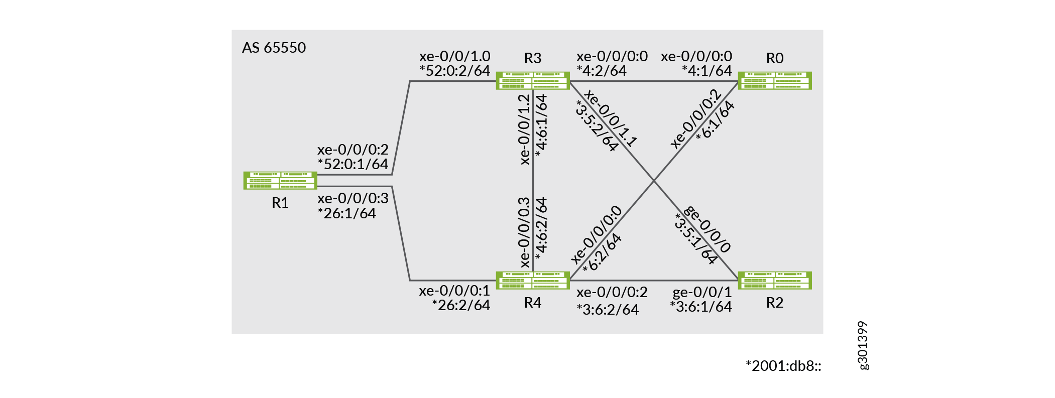
In Figure 4, Router R0 is the ingress and Router R1 and R2 are the egress routers that support IPv4-only customer edge devices. Routers R3 and R4 comprise an IPv6-only provider core network. All routers belong to the same autonomous system. IS-IS is the interior gateway protocol configured to support SRv6 in the IPv6 core routers R3 and R4. In this example, BGP is configured on routers R0, R1, and R2. Router R0 is configured as an IPv6 route reflector with IBGP peering sessions to both Router R1 and Router R2. The egress Router R1 advertises the L3VPN SID to ingress Router R0, which accepts and updates the VRF table.
From R1, BGP routes are advertised with next-hop self to Router R0. Router R0 has two paths to R1, the primary path through R3 and the backup path through R4. In Router R0 , the primary path is with default metric and the backup path is configured with metric 50. Here are some of the routes that are advertised from Router R1 to R0:
| IPv4 | 21.0.0.0 |
| IPv6 | 2001:21:: |
| IPv4 VPN | 31.0.0.0 |
| IPv6 VPN | 2001:31:: |
Configuration
CLI Quick Configuration
To quickly configure this example, copy the
following commands, paste them into a text file, remove any line breaks,
change any details necessary to match your network configuration,
copy and paste the commands into the CLI at the [edit] hierarchy
level, and then enter commit from configuration mode.
Router R0
set chassis network-services enhanced-ip
set interfaces xe-0/0/0:0 unit 0 family inet address 1.4.1.1/30
set interfaces xe-0/0/0:0 unit 0 family iso
set interfaces xe-0/0/0:0 unit 0 family inet6 address 2001:db8::4:1/64

set interfaces xe-0/0/0:2 unit 0 family inet address 1.6.1.1/30
set interfaces xe-0/0/0:2 unit 0 family iso
set interfaces xe-0/0/0:2 unit 0 family inet6 address 2001:db8::6:1/64
set interfaces lo0 unit 0 family inet6 address 2001:db8:1:255::0/128
set policy-options policy-statement adv_global term v4 from route-filter 20.0.0.0/8 orlonger
set policy-options policy-statement adv_global term v4 then next-hop self
set policy-options policy-statement adv_global term v4 then accept
set policy-options policy-statement adv_global term v6 from route-filter 2001:20::/64 orlonger
set policy-options policy-statement adv_global term v6 then next-hop self
set policy-options policy-statement adv_global term v6 then accept
set policy-options policy-statement pplb then load-balance per-packet
set policy-options community vpn1-target members target:100:1
set policy-options community vpn2-target members target:100:2
set routing-instances vpn1 protocols bgp group to-TG-vpn1-v4 type external
set routing-instances vpn1 protocols bgp group to-TG-vpn1-v4 local-address 11.1.1.5
set routing-instances vpn1 protocols bgp group to-TG-vpn1-v4 family inet unicast
set routing-instances vpn1 protocols bgp group to-TG-vpn1-v4 family inet6 unicast
set routing-instances vpn1 protocols bgp group to-TG-vpn1-v4 peer-as 1002
set routing-instances vpn1 protocols bgp group to-TG-vpn1-v4 neighbor 11.1.1.6
set routing-instances vpn1 protocols bgp group to-TG-vpn1-v6 type external
set routing-instances vpn1 protocols bgp group to-TG-vpn1-v6 local-address 2001:11:1:1::5
set routing-instances vpn1 protocols bgp group to-TG-vpn1-v6 family inet6 unicast
set routing-instances vpn1 protocols bgp group to-TG-vpn1-v6 peer-as 1002
set routing-instances vpn1 protocols bgp group to-TG-vpn1-v6 neighbor 2001:11:1:1::6
set routing-instances vpn1 protocols bgp source-packet-routing srv6 locator loc1 end-dt4-sid 3001::4
set routing-instances vpn1 protocols bgp source-packet-routing srv6 locator loc1 end-dt6-sid 3001::5
set routing-instances vpn1 instance-type vrf
set routing-instances vpn1 interface xe-0/0/0:3.1
set routing-instances vpn1 route-distinguisher 100:1
set routing-instances vpn1 vrf-target target:100:1
set routing-options source-packet-routing srv6 locator loc1 3001::/64
set routing-options source-packet-routing srv6 no-reduced-srh
set routing-options router-id 128.53.38.52
set routing-options autonomous-system 100
set routing-options forwarding-table export pplb
set protocols bgp group to-PE-all type internal
set protocols bgp group to-PE-all local-address abcd::128:53:38:52
set protocols bgp group to-PE-all family inet unicast extended-nexthop
set protocols bgp group to-PE-all family inet unicast advertise-srv6-service
set protocols bgp group to-PE-all family inet unicast accept-srv6-service
set protocols bgp group to-PE-all family inet-vpn unicast extended-nexthop
set protocols bgp group to-PE-all family inet-vpn unicast advertise-srv6-service
set protocols bgp group to-PE-all family inet-vpn unicast accept-srv6-service
set protocols bgp group to-PE-all family inet6 unicast advertise-srv6-service
set protocols bgp group to-PE-all family inet6 unicast accept-srv6-service
set protocols bgp group to-PE-all family inet6-vpn unicast advertise-srv6-service
set protocols bgp group to-PE-all family inet6-vpn unicast accept-srv6-service
set protocols bgp group to-PE-all export adv_global
set protocols bgp group to-PE-all cluster 128.53.38.52
set protocols bgp group to-PE-all neighbor abcd::128:53:35:39
set protocols bgp group to-PE-all neighbor abcd::128:53:35:35
set protocols bgp group to-TG-global-v4 type external
set protocols bgp group to-TG-global-v4 local-address 11.1.1.1
set protocols bgp group to-TG-global-v4 family inet unicast
set protocols bgp group to-TG-global-v4 family inet6 unicast
set protocols bgp group to-TG-global-v4 peer-as 1001
set protocols bgp group to-TG-global-v4 neighbor 11.1.1.2
set protocols bgp group to-TG-global-v6 type external
set protocols bgp group to-TG-global-v6 local-address 2001:11:1:1::1
set protocols bgp group to-TG-global-v6 family inet6 unicast
set protocols bgp group to-TG-global-v6 peer-as 1001
set protocols bgp group to-TG-global-v6 neighbor 2001:11:1:1::2
set protocols bgp source-packet-routing srv6 locator loc1 end-dt4-sid 3001::2
set protocols bgp source-packet-routing srv6 locator loc1 end-dt6-sid 3001::3
set protocols isis interface all
set protocols isis interface fxp0.0 disable

set protocols isis level 1 disable
Router R1
set chassis network-services enhanced-ip
set interfaces xe-0/0/0:2 unit 0 family inet address 2.5.1.1/30
set interfaces xe-0/0/0:2 unit 0 family iso
set interfaces xe-0/0/0:2 unit 0 family inet6 address 2001:db8::52:0:1/64
set interfaces xe-0/0/0:3 unit 0 family inet address 2.6.1.1/30
set interfaces xe-0/0/0:3 unit 0 family iso
set interfaces xe-0/0/0:3 unit 0 family inet6 address 2001:db8::26:1/64
set policy-options policy-statement adv_global term v4 from route-filter 21.0.0.0/8 orlonger
set policy-options policy-statement adv_global term v4 from route-filter 12.1.1.1/30 orlonger
set policy-options policy-statement adv_global term v4 then next-hop self
set policy-options policy-statement adv_global term v4 then accept
set policy-options policy-statement adv_global term v6 from route-filter 2001:21::/64 orlonger
set policy-options policy-statement adv_global term v6 from route-filter 2001:12:1:1::1/126 orlonger
set policy-options policy-statement adv_global term v6 then next-hop self
set policy-options policy-statement adv_global term v6 then accept
set policy-options policy-statement adv_vpn1 term v4 from route-filter 31.0.0.0/8 orlonger
set policy-options policy-statement adv_vpn1 term v4 from route-filter 12.1.1.5/30 orlonger
set policy-options policy-statement adv_vpn1 term v4 then community set vpn1-target
set policy-options policy-statement adv_vpn1 term v4 then next-hop self
set policy-options policy-statement adv_vpn1 term v4 then accept
set policy-options policy-statement adv_vpn1 term v6 from route-filter 2001:31::/64 orlonger
set policy-options policy-statement adv_vpn1 term v6 from route-filter 2001:12:1:1::5/126 orlonger
set policy-options policy-statement adv_vpn1 term v6 then community set vpn1-target
set policy-options policy-statement adv_vpn1 term v6 then next-hop self
set policy-options policy-statement adv_vpn1 term v6 then accept
set policy-options policy-statement pplb then load-balance per-packet
set policy-options community vpn1-target members target:100:1
set policy-options community vpn2-target members target:100:2
set routing-instances vpn1 protocols bgp group to-TG-vpn1-v4 type external
set routing-instances vpn1 protocols bgp group to-TG-vpn1-v4 local-address 12.1.1.5
set routing-instances vpn1 protocols bgp group to-TG-vpn1-v4 family inet unicast
set routing-instances vpn1 protocols bgp group to-TG-vpn1-v4 family inet6 unicast
set routing-instances vpn1 protocols bgp group to-TG-vpn1-v4 peer-as 1012
set routing-instances vpn1 protocols bgp group to-TG-vpn1-v4 neighbor 12.1.1.6
set routing-instances vpn1 protocols bgp group to-TG-vpn1-v6 type external
set routing-instances vpn1 protocols bgp group to-TG-vpn1-v6 local-address 2001:12:1:1::5
set routing-instances vpn1 protocols bgp group to-TG-vpn1-v6 family inet6 unicast
set routing-instances vpn1 protocols bgp group to-TG-vpn1-v6 peer-as 1012
set routing-instances vpn1 protocols bgp group to-TG-vpn1-v6 neighbor 2001:12:1:1::6
set routing-instances vpn1 protocols bgp source-packet-routing srv6 locator loc1 end-dt4-sid 3011::4
set routing-instances vpn1 protocols bgp source-packet-routing srv6 locator loc1 end-dt6-sid 3011::5
set routing-instances vpn1 instance-type vrf
set routing-instances vpn1 interface xe-0/0/1:0.1
set routing-instances vpn1 route-distinguisher 100:1
set routing-instances vpn1 vrf-export adv_vpn1
set routing-instances vpn1 vrf-target target:100:1
set routing-options source-packet-routing srv6 locator loc1 3011::/64
set routing-options source-packet-routing srv6 no-reduced-srh
set routing-options rib inet6.3 static route abcd::128:53:38:52/128 next-hop self
set routing-options rib inet6.3 static route abcd::128:53:38:52/128 resolve
set routing-options rib inet6.0 static route abcd::128:53:38:52/128 next-hop self
set routing-options rib inet6.0 static route abcd::128:53:38:52/128 resolve
set routing-options autonomous-system 100
set routing-options forwarding-table export pplb
set protocols bgp group to-RR type internal
set protocols bgp group to-RR local-address abcd::128:53:35:39
set protocols bgp group to-RR family inet unicast extended-nexthop
set protocols bgp group to-RR family inet unicast advertise-srv6-service
set protocols bgp group to-RR family inet unicast accept-srv6-service
set protocols bgp group to-RR family inet-vpn unicast extended-nexthop
set protocols bgp group to-RR family inet-vpn unicast advertise-srv6-service
set protocols bgp group to-RR family inet-vpn unicast accept-srv6-service
set protocols bgp group to-RR family inet6 unicast advertise-srv6-service
set protocols bgp group to-RR family inet6 unicast accept-srv6-service
set protocols bgp group to-RR family inet6-vpn unicast advertise-srv6-service
set protocols bgp group to-RR family inet6-vpn unicast accept-srv6-service
set protocols bgp group to-RR export adv_global
set protocols bgp group to-RR neighbor abcd::128:53:38:52
set protocols bgp group to-TG-global-v4 type external
set protocols bgp group to-TG-global-v4 local-address 12.1.1.1
set protocols bgp group to-TG-global-v4 family inet unicast
set protocols bgp group to-TG-global-v4 family inet6 unicast
set protocols bgp group to-TG-global-v4 peer-as 1011
set protocols bgp group to-TG-global-v4 neighbor 12.1.1.2
set protocols bgp group to-TG-global-v6 type external
set protocols bgp group to-TG-global-v6 local-address 2001:12:1:1::1
set protocols bgp group to-TG-global-v6 family inet6 unicast
set protocols bgp group to-TG-global-v6 peer-as 1011
set protocols bgp group to-TG-global-v6 neighbor 2001:12:1:1::2
set protocols bgp source-packet-routing srv6 locator loc1 end-dt4-sid 3011::2
set protocols bgp source-packet-routing srv6 locator loc1 end-dt6-sid 3011::3
set protocols isis interface all
set protocols isis interface fxp0.0 disable

set protocols isis level 1 disable
Router R2
set chassis network-services enhanced-ip
set interfaces ge-0/0/0 unit 0 family inet address 3.5.1.1/30
set interfaces ge-0/0/0 unit 0 family iso
set interfaces ge-0/0/0 unit 0 family inet6 address 2001:db8::3:5:1/64
set interfaces ge-0/0/1 unit 0 family inet address 3.6.1.1/30
set interfaces ge-0/0/1 unit 0 family iso
set interfaces ge-0/0/1 unit 0 family inet6 address 2001:db8::3:6:1/64
set interfaces lo0 unit 0 family inet6 address 2001:db8:1:255::2/128
set policy-options policy-statement adv_global term v4 from route-filter 22.0.0.0/8 orlonger
set policy-options policy-statement adv_global term v4 from route-filter 13.1.1.1/30 orlonger
set policy-options policy-statement adv_global term v4 then next-hop self
set policy-options policy-statement adv_global term v4 then accept
set policy-options policy-statement adv_global term v6 from route-filter 2001:22::/64 orlonger
set policy-options policy-statement adv_global term v6 from route-filter 2001:13:1:1::1/126 orlonger
set policy-options policy-statement adv_global term v6 then next-hop self
set policy-options policy-statement adv_global term v6 then accept
set policy-options policy-statement adv_vpn1 term v4 from route-filter 32.0.0.0/8 orlonger
set policy-options policy-statement adv_vpn1 term v4 from route-filter 13.1.1.5/30 orlonger
set policy-options policy-statement adv_vpn1 term v4 then community set vpn1-target
set policy-options policy-statement adv_vpn1 term v4 then next-hop self
set policy-options policy-statement adv_vpn1 term v4 then accept
set policy-options policy-statement adv_vpn1 term v6 from route-filter 2001:32::/64 orlonger
set policy-options policy-statement adv_vpn1 term v6 from route-filter 2001:13:1:1::5/126 orlonger
set policy-options policy-statement adv_vpn1 term v6 then community set vpn1-target
set policy-options policy-statement adv_vpn1 term v6 then next-hop self
set policy-options policy-statement adv_vpn1 term v6 then accept
set policy-options policy-statement pplb then load-balance per-packet
set policy-options community vpn1-target members target:100:1
set routing-instances vpn1 protocols bgp group to-TG-vpn1-v4 type external
set routing-instances vpn1 protocols bgp group to-TG-vpn1-v4 local-address 13.1.1.5
set routing-instances vpn1 protocols bgp group to-TG-vpn1-v4 family inet unicast
set routing-instances vpn1 protocols bgp group to-TG-vpn1-v4 family inet6 unicast
set routing-instances vpn1 protocols bgp group to-TG-vpn1-v4 peer-as 1022
set routing-instances vpn1 protocols bgp group to-TG-vpn1-v4 neighbor 13.1.1.6
set routing-instances vpn1 protocols bgp group to-TG-vpn1-v6 type external
set routing-instances vpn1 protocols bgp group to-TG-vpn1-v6 local-address 2001:13:1:1::5
set routing-instances vpn1 protocols bgp group to-TG-vpn1-v6 family inet6 unicast
set routing-instances vpn1 protocols bgp group to-TG-vpn1-v6 peer-as 1022
set routing-instances vpn1 protocols bgp group to-TG-vpn1-v6 neighbor 2001:13:1:1::6
set routing-instances vpn1 protocols bgp source-packet-routing srv6 locator loc1 end-dt4-sid 3021::4
set routing-instances vpn1 protocols bgp source-packet-routing srv6 locator loc1 end-dt6-sid 3021::5
set routing-instances vpn1 instance-type vrf
set routing-instances vpn1 interface ge-0/0/2.1
set routing-instances vpn1 route-distinguisher 100:1
set routing-instances vpn1 vrf-export adv_vpn1
set routing-instances vpn1 vrf-target target:100:1
set routing-options source-packet-routing srv6 locator loc1 3021::/64
set routing-options source-packet-routing srv6 no-reduced-srh
set routing-options rib inet6.3 static route abcd::128:53:38:52/128 next-hop self
set routing-options rib inet6.3 static route abcd::128:53:38:52/128 resolve
set routing-options rib inet6.0 static route abcd::128:53:38:52/128 next-hop self
set routing-options rib inet6.0 static route abcd::128:53:38:52/128 resolve
set routing-options autonomous-system 100
set routing-options forwarding-table export pplb
set protocols bgp group to-RR type internal
set protocols bgp group to-RR local-address abcd::128:53:35:35
set protocols bgp group to-RR family inet unicast extended-nexthop
set protocols bgp group to-RR family inet unicast advertise-srv6-service
set protocols bgp group to-RR family inet unicast accept-srv6-service
set protocols bgp group to-RR family inet-vpn unicast extended-nexthop
set protocols bgp group to-RR family inet-vpn unicast advertise-srv6-service
set protocols bgp group to-RR family inet-vpn unicast accept-srv6-service
set protocols bgp group to-RR family inet6 unicast advertise-srv6-service
set protocols bgp group to-RR family inet6 unicast accept-srv6-service
set protocols bgp group to-RR family inet6-vpn unicast advertise-srv6-service
set protocols bgp group to-RR family inet6-vpn unicast accept-srv6-service
set protocols bgp group to-RR export adv_global
set protocols bgp group to-RR neighbor abcd::128:53:38:52
set protocols bgp group to-TG-global-v4 type external
set protocols bgp group to-TG-global-v4 local-address 13.1.1.1
set protocols bgp group to-TG-global-v4 family inet unicast
set protocols bgp group to-TG-global-v4 family inet6 unicast
set protocols bgp group to-TG-global-v4 peer-as 1021
set protocols bgp group to-TG-global-v4 neighbor 13.1.1.2
set protocols bgp group to-TG-global-v6 type external
set protocols bgp group to-TG-global-v6 local-address 2001:13:1:1::1
set protocols bgp group to-TG-global-v6 family inet6 unicast
set protocols bgp group to-TG-global-v6 peer-as 1021
set protocols bgp group to-TG-global-v6 neighbor 2001:13:1:1::2
set protocols bgp source-packet-routing srv6 locator loc1 end-dt4-sid 3021::2
set protocols bgp source-packet-routing srv6 locator loc1 end-dt6-sid 3021::3
set protocols isis interface all
set protocols isis interface fxp0.0 disable

set protocols isis level 1 disable
Router R3
set chassis network-services enhanced-ip
set interfaces xe-0/0/0:0 unit 0 family inet address 1.4.1.2/30
set interfaces xe-0/0/0:0 unit 0 family iso
set interfaces xe-0/0/0:0 unit 0 family inet6 address 2001:db8::4:2/64
set interfaces xe-0/0/1:0 unit 0 family inet address 2.5.1.2/30
set interfaces xe-0/0/1:0 unit 0 family iso
set interfaces xe-0/0/1:0 unit 0 family inet6 address 2001:db8::52:0:2/64
set interfaces xe-0/0/1:1 unit 0 family inet address 3.5.1.2/30
set interfaces xe-0/0/1:1 unit 0 family iso
set interfaces xe-0/0/1:1 unit 0 family inet6 address 2001:db8::3:5:2/64
set interfaces xe-0/0/1:2 unit 0 family inet address 4.6.1.1/30
set interfaces xe-0/0/1:2 unit 0 family iso
set interfaces xe-0/0/1:2 unit 0 family inet6 address 2001:db8::4:6:1/64
set interfaces lo0 unit 0 family inet6 address 2001:db8:1:255::3/128
set routing-options autonomous-system 100
set protocols isis interface all
set protocols isis interface fxp0.0 disable
set protocols isis level 1 disable
Router R4
set chassis network-services enhanced-ip
set interfaces xe-0/0/0:0 unit 0 family inet address 1.6.1.2/30
set interfaces xe-0/0/0:0 unit 0 family iso
set interfaces xe-0/0/0:0 unit 0 family inet6 address 2001:db8::6:2/64
set interfaces xe-0/0/0:1 unit 0 family inet address 2.6.1.2/30
set interfaces xe-0/0/0:1 unit 0 family iso
set interfaces xe-0/0/0:1 unit 0 family inet6 address 2001:db8::26:2/64
set interfaces xe-0/0/0:2 unit 0 family inet address 3.6.1.2/30
set interfaces xe-0/0/0:2 unit 0 family iso
set interfaces xe-0/0/0:2 unit 0 family inet6 address 2001:db8::3:6:2/64
set interfaces xe-0/0/0:3 unit 0 family inet address 4.6.1.2/30
set interfaces xe-0/0/0:3 unit 0 family iso
set interfaces xe-0/0/0:3 unit 0 family inet6 address 2001:db8::4:6:2/64
set interfaces lo0 unit 0 family inet6 address 2001:db8:1:255::4/128
set routing-options autonomous-system 100
set protocols isis interface all
set protocols isis interface fxp0.0 disable
set protocols isis level 1 disable
Configure Router R0
Step-by-Step Procedure
To configure SRv6 network programming with Layer 3 VPN services, perform the following steps on Router R0:
Configure the device interfaces to enable IP transport.
[edit]
user@R0# set interfaces xe-0/0/0:0 unit 0 family inet address 1.4.1.1/30
user@R0# set interfaces xe-0/0/0:0 unit 0 family iso
user@R0# set interfaces xe-0/0/0:0 unit 0 family inet6 address 2001:db8::4:1/64

user@R0# set interfaces xe-0/0/0:2 unit 0 family inet address 1.6.1.1/30
user@R0# set interfaces xe-0/0/0:2 unit 0 family iso
user@R0# set interfaces xe-0/0/0:2 unit 0 family inet6 address 2001:db8::6:1/64
Configure the router ID and autonomous system (AS) number to propagate routing information within a set of routing devices that belong to the same AS.
[edit]
user@R0# set routing-options router-id 128.53.38.52
user@R0# set routing-options autonomous-system 100
Enable SRv6 globally and the locator address to indicate the SRv6 capability of the router. SRv6 SID is an IPv6 address that consists of the locator and a function. The routing protocols advertise the locator addresses.
[edit]
user@R0# set routing-options source-packet-routing srv6 locator loc1 3001::/64
user@R0# set routing-options source-packet-routing srv6 no-reduced-srh
Configure an external routing instance VPN1 for both IPv4 and IPv6 traffic. Configure the BGP protocol for VPN1 to enable peering and traffic transport between the provider edge devices.
[edit]
user@R0# set routing-instances vpn1 protocols bgp group to-TG-vpn1-v4 type external
user@R0# set routing-instances vpn1 protocols bgp group to-TG-vpn1-v4 local-address 11.1.1.5
user@R0# set routing-instances vpn1 protocols bgp group to-TG-vpn1-v4 family inet unicast
user@R0# set routing-instances vpn1 protocols bgp group to-TG-vpn1-v4 family inet6 unicast
user@R0# set routing-instances vpn1 protocols bgp group to-TG-vpn1-v4 peer-as 1002
user@R0# set routing-instances vpn1 protocols bgp group to-TG-vpn1-v4 neighbor 11.1.1.6
user@R0# set routing-instances vpn1 protocols bgp group to-TG-vpn1-v6 type external
user@R0# set routing-instances vpn1 protocols bgp group to-TG-vpn1-v6 local-address 2001:11:1:1::5
user@R0# set routing-instances vpn1 protocols bgp group to-TG-vpn1-v6 family inet6 unicast
user@R0# set routing-instances vpn1 protocols bgp group to-TG-vpn1-v6 peer-as 1002
user@R0# set routing-instances vpn1 protocols bgp group to-TG-vpn1-v6 neighbor 2001:11:1:1::6
Configure the VPN type and a unique route distinguisher for each PE router participating in the routing instance.
[edit]
user@R0# set routing-instances vpn1 instance-type vrf
user@R0# set routing-instances vpn1 interface xe-0/0/0:3.1
user@R0# set routing-instances vpn1 route-distinguisher 100:1
user@R0# set routing-instances vpn1 vrf-target target:100:1
Configure the end-dt4 and end-dt6 SID values for enabling the Layer 3 VPN services.
[edit]
user@R0# set routing-instances vpn1 protocols bgp source-packet-routing srv6 locator loc1 end-dt4-sid 3001::4
user@R0# set routing-instances vpn1 protocols bgp source-packet-routing srv6 locator loc1 end-dt6-sid 3001::5
Define a policy to load-balance packets.
[edit]
user@R0# set policy-options policy-statement pplb then load-balance per-packet
user@R0# set policy-options community vpn1-target members target:100:1
user@R0# set policy-options community vpn2-target members target:100:2
Apply the per-packet policy to enable load balancing of traffic.
[edit]
user@R0# set routing-options forwarding-table export pplb
Define a policy adv_global to accept routes advertised from R1.
[edit]
user@R0# set policy-options policy-statement adv_global term v4 from route-filter 20.0.0.0/8 orlonger
user@R0# set policy-options policy-statement adv_global term v4 then next-hop self
user@R0# set policy-options policy-statement adv_global term v4 then accept
user@R0# set policy-options policy-statement adv_global term v6 from route-filter 2001:20::/64 orlonger
user@R0# set policy-options policy-statement adv_global term v6 then next-hop self
user@R0# set policy-options policy-statement adv_global term v6 then accept
Configure BGP on the core-facing interface to establish internal and external peering sessions.
[edit]
user@R0# set protocols bgp group to-PE-all type internal
user@R0# set protocols bgp group to-PE-all local-address abcd::128:53:38:52
user@R0# set protocols bgp group to-PE-all family inet unicast extended-nexthop
user@R0# set protocols bgp group to-PE-all family inet unicast advertise-srv6-service
user@R0# set protocols bgp group to-PE-all family inet unicast accept-srv6-service
user@R0# set protocols bgp group to-PE-all family inet-vpn unicast extended-nexthop
user@R0# set protocols bgp group to-PE-all export adv_global
user@R0# set protocols bgp group to-PE-all cluster 128.53.38.52
user@R0# set protocols bgp group to-PE-all neighbor abcd::128:53:35:39
user@R0# set protocols bgp group to-PE-all neighbor abcd::128:53:35:35
user@R0# set protocols bgp group to-TG-global-v4 type external
user@R0# set protocols bgp group to-TG-global-v4 local-address 11.1.1.1
user@R0# set protocols bgp group to-TG-global-v4 family inet unicast
user@R0# set protocols bgp group to-TG-global-v4 family inet6 unicast
user@R0# set protocols bgp group to-TG-global-v4
user@R0# set protocols bgp group to-TG-global-v4 neighbor 11.1.1.2
user@R0# set protocols bgp group to-TG-global-v6 type external
user@R0# set protocols bgp group to-TG-global-v6 local-address 2001:11:1:1::1
user@R0# set protocols bgp group to-TG-global-v6 family inet6 unicast
user@R0# set protocols bgp group to-TG-global-v6 peer-as 1001
user@R0# set protocols bgp group to-TG-global-v6 neighbor 2001:11:1:1::2
Enable the device to advertise the SRv6 services to BGP peers and to accept the routes advertised by the egress provider edge (PE) devices.
[edit]
user@R0# set protocols bgp group to-PE-all family inet-vpn unicast advertise-srv6-service
user@R0# set protocols bgp group to-PE-all family inet-vpn unicast accept-srv6-service
user@R0# set protocols bgp group to-PE-all family inet6 unicast advertise-srv6-service
user@R0# set protocols bgp group to-PE-all family inet6 unicast accept-srv6-service
user@R0# set protocols bgp group to-PE-all family inet6-vpn unicast advertise-srv6-service
user@R0# set protocols bgp group to-PE-all family inet6-vpn unicast accept-srv6-service
Enable IS-IS as the interior gateway protocol (IGP) for routing traffic between the core provider routers.
[edit]
user@R0# set protocols isis interface all
user@R0# set protocols isis interface fxp0.0 disable
user@R0#
user@R0# set protocols isis level 1 disable
Configure the end-dt4 and end-dt6 SID value for the prefix segments. End-dt4 is the endpoint SID with decapsulation and IPv4 table lookup and end-dt6 is the endpoint with decapsulation and IPv6 table lookup. BGP allocates these for IPv4 and IPv6 Layer3 VPN services SIDs.
[edit]
user@R0# set protocols bgp source-packet-routing srv6 locator loc1 end-dt4-sid 3001::2
user@R0# set protocols bgp source-packet-routing srv6 locator loc1 end-dt6-sid 3001::3
Results
From configuration mode, confirm your configuration
by entering the show interfaces, show protocols, show policy-options, and show routing-options commands. If the output does not display the intended configuration,
repeat the instructions in this example to correct the configuration.
[edit]
user@R0# show interfaces
xe-0/0/0:0 {
    unit 0 {
        family inet {
            address 1.4.1.1/30;
        }
        family iso;
        family inet6 {
            address 2001:db8::4:1/64;
        }
    }
}
xe-0/0/0:1 {
    unit 0 {
        family inet {
            address 1.5.1.1/30;
        }
        family iso;
        family inet6 {
            address 2001:1:4:2::1/126;
        }
    }
}
xe-0/0/0:2 {
    unit 0 {
        family inet {
            address 1.6.1.1/30;
        }
        family iso;
        family inet6 {
            address 2001:db8::6:1/64;
        }
    }
}
[edit]
user@R0# show protocols
bgp {
    group to-PE-all {
        type internal;
        local-address abcd::128:53:38:52;
        family inet {
            unicast {
                extended-nexthop;
                advertise-srv6-service;
                accept-srv6-service;
            }
        }
        family inet-vpn {
            unicast {
                extended-nexthop;
                advertise-srv6-service;
                accept-srv6-service;
            }
        }
        family inet6 {
            unicast {
                advertise-srv6-service;
                accept-srv6-service;
            }
        }
        family inet6-vpn {
            unicast {
                advertise-srv6-service;
                accept-srv6-service;
            }
        }
        export adv_global;
        cluster 128.53.38.52;
        neighbor abcd::128:53:35:39;
        neighbor abcd::128:53:35:35;
    }
    group to-TG-global-v4 {
        type external;
        local-address 11.1.1.1;
        family inet {
            unicast;
        }
        family inet6 {
            unicast;
        }
        peer-as 1001;
        neighbor 11.1.1.2;
    }
    group to-TG-global-v6 {
        type external;
        local-address 2001:11:1:1::1;
        family inet6 {
            unicast;
        }
        peer-as 1001;
        neighbor 2001:11:1:1::2;
    }
    source-packet-routing {
        srv6 {
            locator loc1 {
                end-dt4-sid 3001::2;
                end-dt6-sid 3001::3;
            }
        }
    }
}
isis {
    interface all;
    interface fxp0.0 {
        disable;
    }

    level 1 disable;
}
[edit]
user@R0# show policy-options
policy-options {
    policy-statement adv_global {
        term v4 {
            from {
                route-filter 20.0.0.0/8 orlonger;
            }
            then {
                next-hop self;
                accept;
            }
        }
        term v6 {
            from {
                route-filter 2001:20::/64 orlonger;
            }
            then {
                next-hop self;
                accept;
            }
        }
    }
    policy-statement pplb {
        then {
            load-balance per-packet;
        }
    }
    community vpn1-target members target:100:1;
    community vpn2-target members target:100:2;
}
[edit]
user@R0# show routing-options
routing-options {
    source-packet-routing {
        srv6 {
            locator loc1 3001::/64;
            no-reduced-srh;
        }
    }

    router-id 128.53.38.52;
    autonomous-system 100;
    forwarding-table {
        export pplb;
    }
}
[edit]
user@R0# show routing-instances
routing-instances {
    vpn1 {
        protocols {
            bgp {
                group to-TG-vpn1-v4 {
                    type external;
                    local-address 11.1.1.5;
                    family inet {
                        unicast;
                    }
                    family inet6 {
                        unicast;
                    }
                    peer-as 1002;
                    neighbor 11.1.1.6;
                }
                group to-TG-vpn1-v6 {
                    type external;
                    local-address 2001:11:1:1::5;
                    family inet6 {
                        unicast;
                    }
                    peer-as 1002;
                    neighbor 2001:11:1:1::6;
                }
                source-packet-routing {
                    srv6 {
                        locator loc1 {
                            end-dt4-sid 3001::4;
                            end-dt6-sid 3001::5;
                        }
                    }
                }
            }
        }
        instance-type vrf;
        interface xe-0/0/0:3.1;
        route-distinguisher 100:1;
        vrf-target target:100:1;
    }
}
When done configuring the device, enter commit from
the configuration mode.
Verification
Confirm that the configuration is working properly.
- Verify that the advertised IPv4 route is installed in the IPv4 table
- Verify that SRv6 SID is installed in the IPv4 Table
- Verify that the IPv6 VPN route is installed in the VPN table
- Verify that the IPv4 VPN route is installed in the VPN table
Verify that the advertised IPv4 route is installed in the IPv4 table
Purpose
Verify that ingress router R0 has learned the route to the IPv4 prefix 21.0.0.0 from the egress router R1.
Action
From operational mode, run the show route 21.0.0.0 command on router R0.
user@R0> show route 21.0.0.0
inet.0: 59 destinations, 59 routes (59 active, 0 holddown, 0 hidden)
+ = Active Route, - = Last Active, * = Both

21.0.0.0/30        *[BGP/170] 09:15:25, localpref 100, from abcd::128:53:37:72
                      AS path: {65501} I, validation-state: unverified
                    >  to fe80::2e6b:f5ff:fe28:2bcb via ae0.0, SRV6-Tunnel, Dest: 3011::
                       to fe80::2e6b:f5ff:fe28:2b04 via xe-0/0/0:2.0, SRV6-Tunnel, Dest: 3011::
                       to fe80::2e6b:f5ff:fe73:1e01 via xe-0/0/0:3.0, SRV6-Tunnel, Dest: 3011::
Meaning
The output confirms that the IPv4 prefix 21.0.0.0 is installed in the inet.0 table.
Verify that SRv6 SID is installed in the IPv4 Table
Purpose
Verify that ingress Router R0 has received and accepted the SRv6 end-dt4 SID 3011::2 from the egress Router R1.
Action
From operational mode, run the show route 21.0.0.0 extensive command on Router R0.
user@> show route 21.0.0.0 extensive
inet.0: 59 destinations, 59 routes (59 active, 0 holddown, 0 hidden)
21.0.0.0/30 (1 entry, 1 announced)
TSI:
KRT in-kernel 21.0.0.0/30 -> {composite(716)}
        *BGP    Preference: 170/-101
                Next hop type: Indirect, Next hop index: 0
                Address: 0xc5aa39c
                Next-hop reference count: 20
                Source: abcd::128:53:37:72
                Next hop type: List, Next hop index: 1048574
        Next hop: ELNH Address 0xc5a9e88, selected
            Next hop type: Chain, Next hop index: 725
            Address: 0xc5a9e88
            Next-hop reference count: 1
            Next hop: ELNH Address 0xc5a9aa0
            SRV6-Tunnel: Reduced-SRH Encap-mode
             Src: abcd::128:53:35:39 Dest: 3011::
             Segment-list[0] 3011::
                Next hop type: Router, Next hop index: 700
                Address: 0xc5a9aa0
                Next-hop reference count: 4
                Next hop: fe80::2e6b:f5ff:fe28:2bcb via ae0.0
        Next hop: ELNH Address 0xc5a9eec
            Next hop type: Chain, Next hop index: 726
            Address: 0xc5a9eec
            Next-hop reference count: 1
            Next hop: ELNH Address 0xc5a9c30
            SRV6-Tunnel: Reduced-SRH Encap-mode
             Src: abcd::128:53:35:39 Dest: 3011::
             Segment-list[0] 3011::
                Next hop type: Router, Next hop index: 702
                Address: 0xc5a9c30
                Next-hop reference count: 4
                Next hop: fe80::2e6b:f5ff:fe28:2b04 via xe-0/0/0:2.0
        Next hop: ELNH Address 0xc5aa0e0
            Next hop type: Chain, Next hop index: 727
            Address: 0xc5aa0e0
            Next-hop reference count: 1
            Next hop: ELNH Address 0xc5a9780
            SRV6-Tunnel: Reduced-SRH Encap-mode
             Src: abcd::128:53:35:39 Dest: 3011::
             Segment-list[0] 3011::
                Next hop type: Router, Next hop index: 647
                Address: 0xc5a9780
                Next-hop reference count: 20
                Next hop: fe80::2e6b:f5ff:fe73:1e01 via xe-0/0/0:3.0
                Protocol next hop: abcd::128:53:37:72
                Composite next hop: 0xbd4e7d0 716 INH Session ID: 0x151
                Indirect next hop: 0xc762204 1048582 INH Session ID: 0x151
                State: <Active int Ext>
                Local AS:   100 Peer AS:   100
                Age: 9:13:44    Metric2: 20
                Validation State: unverified
                ORR Generation-ID: 0
                Task: BGP_100.abcd::128:53:37:72
                Announcement bits (1): 0-KRT
                AS path: {65501}
                Accepted
                SRv6 SID: 3011::2
                Localpref: 100
                Router ID: 128.53.37.72
                Composite next hops: 1
                         Protocol next hop: abcd::128:53:37:72 Metric: 20
                         Composite next hop: 0xbd4e7d0 716 INH Session ID: 0x151
                         Indirect next hop: 0xc762204 1048582 INH Session ID: 0x151
                         Indirect path forwarding next hops: 3
                                 Next hop type: List
                                 Next hop: fe80::2e6b:f5ff:fe28:2bcb via ae0.0
                                 Next hop: fe80::2e6b:f5ff:fe28:2b04 via xe-0/0/0:2.0
                                 Next hop: fe80::2e6b:f5ff:fe73:1e01 via xe-0/0/0:3.0
                                 abcd::128:53:37:72/128 Originating RIB: inet6.3
                                   Metric: 20 Node path count: 1
                                   Indirect next hops: 1
                                 Protocol next hop: 3011:: Metric: 20
                                 Inode flags: 0x206 path flags: 0x0
                                 Path fnh link: 0xc3bf4c0 path inh link: 0x0
                                 Indirect next hop: 0xc76cd04 - INH Session ID: 0x0
                                 Indirect path forwarding next hops: 3
                                         Next hop type: List
                                         Next hop: fe80::2e6b:f5ff:fe28:2bcb via ae0.0
                                         Next hop: fe80::2e6b:f5ff:fe28:2b04 via xe-0/0/0:2.0
                                         Next hop: fe80::2e6b:f5ff:fe73:1e01 via xe-0/0/0:3.0
                                         3011:: Originating RIB: inet6.3
                                           Metric: 20 Node path count: 1
                                           Forwarding nexthops: 3
                                                 Next hop type: List
                                                 Next hop: fe80::2e6b:f5ff:fe28:2bcb via ae0.0
                                                 Next hop: fe80::2e6b:f5ff:fe28:2b04 via xe-0/0/0:2.0
                                                 Next hop: fe80::2e6b:f5ff:fe73:1e01 via xe-0/0/0:3.0
Meaning
The output displays the SRv6 SID and confirms that an SRv6 tunnel is established between Routers R0 and R1.
Verify that the IPv6 VPN route is installed in the VPN table
Purpose
Verify that ingress router R0 has learned the route to the VPN IPv6 prefix 2001::30::/126 from the egress router R1.
Action
From operational mode, run the show route 2001:31:: command on router R0.
user@R0> show route 2001:31::
vpn1.inet6.0: 36 destinations, 36 routes (36 active, 0 holddown, 0 hidden)
+ = Active Route, - = Last Active, * = Both

2001:31::/126      *[BGP/170] 09:15:40, localpref 100, from abcd::128:53:37:72
                      AS path: {65502} I, validation-state: unverified
                    >  to fe80::2e6b:f5ff:fe28:2bcb via ae0.0, SRV6-Tunnel, Dest: 3011::
                       to fe80::2e6b:f5ff:fe28:2b04 via xe-0/0/0:2.0, SRV6-Tunnel, Dest: 3011::
                       to fe80::2e6b:f5ff:fe73:1e01 via xe-0/0/0:3.0, SRV6-Tunnel, Dest: 3011::
Meaning
The output confirms that the route details for the prefix 2001:31::/126 are installed in the vpn.inet6.0 table.
Verify that the IPv4 VPN route is installed in the VPN table
Purpose
Verify that ingress router R0 has learned the route to the VPN IPv4 prefix 31.0.0.0 from the egress router R1.
Action
From operational mode, run the show route 31.0.0.0 command on router R0.
user@R0> show route 31.0.0.0
vpn1.inet.0: 34 destinations, 34 routes (34 active, 0 holddown, 0 hidden)
+ = Active Route, - = Last Active, * = Both

31.0.0.0/30        *[BGP/170] 09:15:29, localpref 100, from abcd::128:53:37:72
                      AS path: {65502} I, validation-state: unverified
                       to fe80::2e6b:f5ff:fe28:2bcb via ae0.0, SRV6-Tunnel, Dest: 3011::
                       to fe80::2e6b:f5ff:fe28:2b04 via xe-0/0/0:2.0, SRV6-Tunnel, Dest: 3011::
                    >  to fe80::2e6b:f5ff:fe73:1e01 via xe-0/0/0:3.0, SRV6-Tunnel, Dest: 3011::
Meaning
The output confirms that the IPv4 prefix 31.0.0.0 is installed in the vpn.inet.0 table.
Overview of SR-TE Policy for SRv6 Tunnel
- Benefits of SRv6 TE Policy
- SRv6 TE Policy Overview
- What is a Segment Routing Extension Header?
- TI-LFA for SRv6 TE
- Layer 3 VPN Services Over the SRv6 Core
- Advertising Layer 3 VPN Services to BGP Peers
- Supported and Unsupported Features for SRv6 Network Programming in SR-TE
Benefits of SRv6 TE Policy
- Flexible deployment—With SRv6 TE you can leverage segment routing without deploying MPLS. Such networks depend only on the IPv6 headers and header extensions for transmitting data. This is useful for service providers whose networks are predominantly IPv6 and have not deployed MPLS.
- Enhanced scalability—SRv6 TE improves scalability by ensuring that you can complete the deployment without any major hardware or software upgrade in a core IPv6 network.
- Improved efficiency—SRv6 TE uses IS-IS SRv6 SIDs to form the segment lists. Therefore, it leverages the TI-LFA paths of IS-IS SRv6 SIDs and can form backup paths based on the IGP.
- Load balancing—SRv6 TE leverages IS-IS weighted equal cost multipath (ECMP) and can also have its own ECMPs on individual segment lists to form hierarchical weighted ECMPs that performs load balancing at a granular level.
SRv6 TE Policy Overview
An SR-TE policy contains one or more SR-TE tunnels either configured statically or contributed by different tunnel sources namely PCEP, BGP-SRTE, DTM. Junos OS supports SRv6 data plane with statically configured SR-TE policy.
In an SRv6 TE policy:
- IS-IS configuration populates the core.
- SRv6 TE tunnel configuration populates the transport.
- BGP network layer reachability information (NLRI) populates the service.
After creating an SRv6 TE data plane, you can enable Layer 3 overlay services with BGP as the control plane and SRv6 as the data plane. The desired payload can be of IPv4 or IPv6.
Figure 5 depicts an SRv6 TE topology in which R1 is the ingress node with SRv6 TE policy configured to R6. R6 is the egress node with Layer 3 VPN services to BGP peers configured. The core constitutes IS-IS SRv6. The egress Router R6 advertises the L3VPN SID to ingress Router R1, which accepts and updates the VRF table. R6 is configured with 2001:db8:0:a6::d06 as End-SID and the L3VPN service is exported towards CE7 to R1 with 2001:db8:0:a6::d06 as next hop. There are two segment lists: <R4, R5, R6> and <R2, R3, R6>.
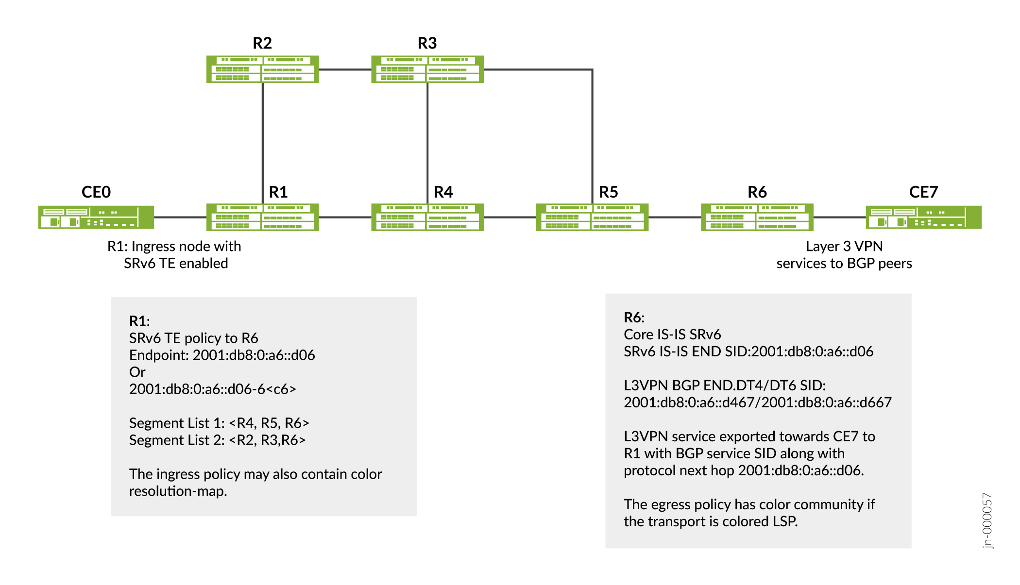
What is a Segment Routing Extension Header?
A Segment Identifier (SID) represents a specific segment in a segment routing domain. In an IPv6 network, the SID-type used is a 128-bit IPv6 address also referred to as an SRv6 Segment or SRv6 SID. SRv6 stacks up these IPv6 addresses instead of MPLS labels in a segment routing extension header. The Segment Routing Extension Header (SRH) is a type of IPv6 routing extension header. Typically, the SRH contains a segment list encoded as an SRv6 SID. An SRv6 SID consists of the following parts:
-
Locator—Locator is the first part of a SID that consists of the most significant bits representing the address of a particular SRv6 node. The locator is very similar to a network address that provides a route to its parent node. The IS-IS protocol installs the locator route in the
inet6.0routing table. IS-IS routes the segment to its parent node, which subsequently performs a function defined in the other part of the SRv6 SID. You can also specify the algorithm associated with this locator. -
Function—The other part of the SID defines a function that is performed locally on the node that is specified by the locator. There are several functions that have already been defined in the Internet draft draft-ietf-spring-srv6-network-programming-07draft, SRv6 Network Programming. However, we have implemented the following functions are available on Junos OS that are signalled in IS-IS. IS-IS installs these function SIDs in the
inet6.0routing table.-
End—An endpoint function for SRv6 instantiation of a Prefix SID. It does not allow for decapsulation of an outer header for the removal of an SRH. Therefore, an End SID cannot be the last SID of a SID list and cannot be the Destination Address (DA) of a packet without an SRH (unless combined with the PSP, USP or USD flavors).
-
End.X—An endpoint X function is an SRv6 instantiation of an adjacent SID. It is a variant of the endpoint function with Layer 3 cross-connect to an array of Layer 3 adjacencies.
You can specify End SID behavior such as Penultimate Segment Pop (PSP), Ultimate Segment Pop (USP) or Ultimate Segment Decapsulation (USD).
-
PSP—When the last SID is written in the destination address, the End and End.X functions with the PSP flavor pop the top-most SRH. Subsequent stacked SRHs may be present but are not processed as part of the function.
-
USP—When the next header is an SRH and there are no more segments left, the IS-IS protocol pops the top SRH, looks up the updated destination address and forwards the packet based on match table entry.
-
USD—When the next Header in the packet is 41 or is an SRH and there are no more segments left, then IS-IS pops the outer IPv6 header and its extension headers, looks up the exposed inner IP destination address and forwards the packet to the matched table entry.
-
For example, you can have an SRv6 SID where 2001::19:db8:AC05:FF01:FF01: is the locator and A000:B000:C000:A000 is the function:
|
Locator |
Function |
|
2001::db8:19:AC05:FF01:FF01 |
A000:B000:C000:A000 |
TI-LFA for SRv6 TE
Topology Independent- Loop Free Alternate (TI-LFA) establishes a Fast Reroute (FRR) path that is aligned to a post-convergence path. An SRv6-capable node inserts a single segment into the IPv6 header or multiple segments into the SRH. Multiple SRHs can significantly raise the encapsulation overhead, which can sometimes be more than the actual packet payload. Therefore, by default, Junos OS supports SRv6 TE tunnel encapsulation with reduced SRH. The point-of-local repair (PLR) adds the FRR path information to the SRH containing the SRv6 SIDs.
The TI-LFA backup path is represented as a group of SRv6 SIDs inside an SRH. At the ingress router, IS-IS encapsulates the SRH in a fresh IPv6 header. However, at transit routers, IS-IS inserts the SRH into the data traffic in the following manner:
-
Encap Mode—In the encap mode, the original IPv6 packet is encapsulated and transported as the inner packet of an IPv6-in-IPv6 encapsulated packet. The outer IPv6 packet carries the SRH with the segment list. The original IPv6 packet travels unmodified in the network. By default, Junos OS supports SRv6 tunnel encapsulation in reduced SRH. However, you can choose one of the following tunnel encapsulation methods:
-
Reduced SRH (default)—With the reduced SRH mode, ifbecause there is only one SID, there is no SRH added and the last SID is copied into the IPV6 destination address. You cannot preserve the entire SID list in the SRH with a reduced SRH.
-
Non-reduced SRH—You can configure the non-reduced SRH tunnel encapsulation mode when you and might still want to preserve the entire SID list in the SRH.
-
Because the core network of statically configured SRv6 TE LSP is formed by IS-IS SRv6, the IS-IS SRv6 TILFA can be leveraged using SRv6 TE segments.
Layer 3 VPN Services Over the SRv6 Core
When connecting to the egress PE, the ingress PE encapsulates the payload in an outer IPv6 header where the destination address is the SRv6 service SID associated with the related BGP route update. The egress PE sets the next hop to one of its IPv6 addresses that is also the SRv6 locator from which the SRv6 service SID is allocated. Multiple routes can resolve through the same segment routing policy.
You can configure BGP-based Layer 3 service over the SRv6 core. You can enable Layer 3 overlay services with BGP as the control plane and SRv6 as the dataplane.
Advertising Layer 3 VPN Services to BGP Peers
BGP advertises the reachability of prefixes of a particular service from an egress PE device to ingress PE nodes. BGP messages exchanged between PE devices carry SRv6 service SIDs, which BGP uses to interconnect PE devices to form VPN sessions. For Layer 3 VPN services where BGP uses a per-VRF SID allocation, the same SID is shared across multiple network layer reachability information (NLRI) address families.
Egress PE devices that support SRv6-based Layer 3 services advertise overlay service prefixes along with a service SID. The BGP ingress node receives these advertisements and adds the prefix to the corresponding virtual routing and forwarding (VRF) table.
Supported and Unsupported Features for SRv6 Network Programming in SR-TE
SRv6 TE currently supports:
-
IPv4 and IPv6 payloads.
-
Up to 6 SIDs in reduced mode at the ingress router and upto 5 SIDs in non-reduced mode at the ingress.
-
Encapsulation mode on the ingress router.
-
preserve-nexthop-hierarchyconfiguration under resolver for platform layer to be able to combine SIDs from SR-TE and IGP routes.
SRv6 TE currently does not support:
-
Local CSPF capabilities for SRv6 policies.
-
IPv4-colored tunnel endpoint.
-
sBFD and Telemetry.
-
PCE initiated and delegated SRv6 LSPs.
-
Auto-translation with SRv6 SIDs.
-
LDP tunneling with an SRv6 policy.
-
Logical Systems.
-
SR-TE binding SID for an SR-TE tunnel.
-
Ping or OAM for SRTE SRv6.
-
Any Static IPv4 route over SRv6 TE tunnel.
-
Insert mode for SRv6 TE.
-
SRv6 flexible algorithm for SRv6 TE LSPs.
See Also
Example: Configuring Static SR-TE Policy for an SRv6 Tunnel
Overview
This example shows how to configure static SR-TE policy for an SRv6 Tunnel. This SRv6 TE policy is useful for service providers whose networks are predominantly IPv6 and have not deployed MPLS. Such networks depend only on the IPv6 headers and header extensions for transmitting data. SRv6 network programming provides flexibility to leverage segment routing without deploying MPLS.
Topology
The following illustration depicts an SRv6 TE topology in which the device R1 and device R6 are the ingress and egress routers that support IPv4 or IPv6 devices CE1 and CE2. The devices R2, R3, R4, and R5 comprise an IPv6 only provider core network. All the devices belong to the same autonomous system. IS-IS is the interior gateway protocol in the IPv6 core and is configured to support SRv6. In this example, the egress device R6 advertises the L3VPN SID to the ingress device R1, which accepts and updates the VRF table. The device R6 is configured with 2001:db8:0:a6::d06 as end-sid and the L3VPN service is exported towards CE7 to R1 with 2001:db8:0:a6::d06 as next hop. There are two segment lists: <R4, R5, R6> and <R2, R3, R6>.
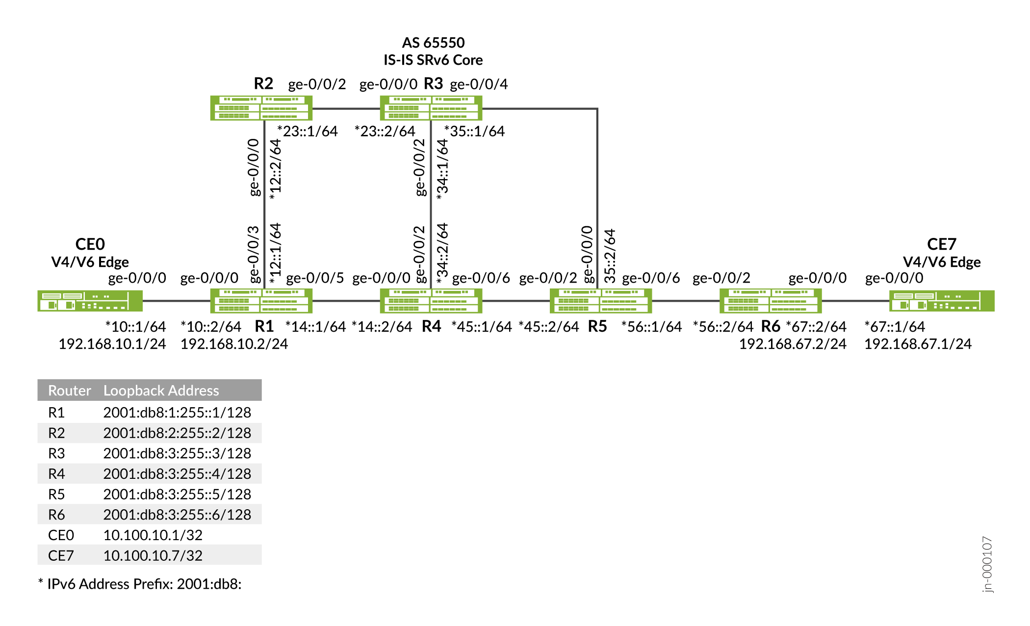
Requirements
This example uses the following hardware and software components:
-
Six MX Series routers.
-
Junos OS Release 21.3R1 or later.
Configuration
CLI Quick Configuration
To quickly configure this example, copy the following commands, paste them into a text file, remove any line breaks, change any details necessary to match your network configuration, and then copy and paste the commands into the CLI at the [edit] hierarchy level , and then enter commit from configuration mode.
Device R1
set interfaces ge-0/0/0 unit 0 description R1_to_CE0
set interfaces ge-0/0/0 unit 0 family inet address 192.168.10.2/24
set interfaces ge-0/0/0 unit 0 family iso
set interfaces ge-0/0/0 unit 0 family inet6 address 2001:db8:10::2/64
set interfaces ge-0/0/3 unit 0 description R1_to_R2
set interfaces ge-0/0/3 unit 0 family iso
set interfaces ge-0/0/3 unit 0 family inet6 address 2001:db8:12::1/64
set interfaces ge-0/0/3 unit 0 description R1_to_R4
set interfaces ge-0/0/5 unit 0 family iso
set interfaces ge-0/0/5 unit 0 family inet6 address 2001:db8:14::1/64
set interfaces lo0 unit 0 family iso address 49.0001.0001.0101.0100
set interfaces lo0 unit 0 family inet6 address 2001:db8:1:255::1/128
set policy-options policy-statement to_CE0_community_export term 0 then community add to_CE0_community
set policy-options policy-statement to_CE0_community_export term 0 then next-hop 2001:db8:0:a1::d01
set policy-options policy-statement to_CE0_community_export term 0 then accept
set policy-options policy-statement to_CE0_community_import term 0 from community to_CE0_community
set policy-options policy-statement to_CE0_community_import term 0 then accept
set policy-options policy-statement v4vpn1_res_map1 term 1 from protocol bgp
set policy-options policy-statement v4vpn1_res_map1 term 1 then accept
set policy-options policy-statement v4vpn1_res_map1 term 1 then resolution-map map1
set policy-options policy-statement v6vpn1_res_map1 term 1 from family inet6-vpn
set policy-options policy-statement v6vpn1_res_map1 term 1 from protocol bgp
set policy-options policy-statement v6vpn1_res_map1 term 1 then accept
set policy-options policy-statement v6vpn1_res_map1 term 1 then resolution-map map1
set policy-options policy-statement LBPP term 1 then load-balance per-packet
set policy-options policy-statement mpath-resolve then multipath-resolve
set policy-options resolution-map map1 mode ip-color
set policy-options community to_CE0_community members target:65500:1
set routing-instances to_CE0 instance-type vrf
set routing-instances to_CE0 protocols bgp group to_CE0_v6 type external
set routing-instances to_CE0 protocols bgp group to_CE0_v6 as-override
set routing-instances to_CE0 protocols bgp group to_CE0_v6 peer-as 65000
set routing-instances to_CE0 protocols bgp group to_CE0_v6 neighbor 2001:db8:10::1
set routing-instances to_CE0 protocols bgp group to_CE0_v4 type external
set routing-instances to_CE0 protocols bgp group to_CE0_v4 as-override
set routing-instances to_CE0 protocols bgp group to_CE0_v4 peer-as 65000
set routing-instances to_CE0 protocols bgp group to_CE0_v4 neighbor 192.168.10.1
set routing-instances to_CE0 protocols bgp source-packet-routing srv6 locator loc1 end-dt4-sid 2001:db8:0:a1::d410
set routing-instances to_CE0 protocols bgp source-packet-routing srv6 locator loc1 end-dt6-sid 2001:db8:0:a1::d610
set routing-instances to_CE0 interface ge-0/0/0.0
set routing-instances to_CE0 route-distinguisher 192.168.255.11:1
set routing-instances to_CE0 vrf-import to_CE0_community_import
set routing-instances to_CE0 vrf-export to_CE0_community_export
set routing-options source-packet-routing srv6 locator loc1 2001:db8:0:a1::/112
set routing-options resolution preserve-nexthop-hierarchy
set routing-options resolution rib bgp.l3vpn-inet6.0 resolution-ribs inet6.3
set routing-options resolution rib bgp.l3vpn-inet6.0 inet6-resolution-ribs inet6.3
set routing-options resolution rib bgp.l3vpn-inet6.0 import mpath-resolve
set routing-options resolution rib bgp.l3vpn-inet6.0 inet6-import mpath-resolve
set routing-options resolution rib bgp.l3vpn-inet6.0 junos-rti-tc-<color>.inet6-import mpath-resolve
set routing-options resolution rib bgp.l3vpn.0 import mpath-resolve
set routing-options resolution rib bgp.l3vpn.0 inet6-import mpath-resolve
set routing-options resolution rib inet6.0 import mpath-resolve
set routing-options resolution rib inet.0 import mpath-resolve
set routing-options router-id 192.168.255.11
set routing-options autonomous-system 65500
set routing-options forwarding-table srv6-chain-merge
set routing-options forwarding-table export LBPP
set protocols bgp group to_R6_ibgpv6 type internal
set protocols bgp group to_R6_ibgpv6 family inet-vpn unicast accept-srv6-service
set protocols bgp group to_R6_ibgpv6 family inet6 unicast extended-nexthop-color
set protocols bgp group to_R6_ibgpv6 family inet6-vpn unicast advertise-srv6-service
set protocols bgp group to_R6_ibgpv6 family inet6-vpn unicast accept-srv6-service
set protocols bgp group to_R6_ibgpv6 local-address 2001:db8:1:255::1
set protocols bgp group to_R6_ibgpv6 import v4vpn1_res_map1
set protocols bgp group to_R6_ibgpv6 import v6vpn1_res_map1
set protocols bgp group to_R6_ibgpv6 family inet unicast extended-nexthop
set protocols bgp group to_R6_ibgpv6 family inet-vpn unicast extended-nexthop
set protocols bgp group to_R6_ibgpv6 family inet-vpn unicast advertise-srv6-serviceset protocols bgp group to_R6_ibgpv6 neighbor 2001:db8:6:255::6
set protocols bgp multipath
set protocols isis interface ge-0/0/3.0 level 2 disable
set protocols isis interface ge-0/0/3.0 level 1 srv6-adjacency-segment unprotected locator loc1 end-x-sid 2001:db8:0:a1::1a12 flavor psp
set protocols isis interface ge-0/0/3.0 level 1 srv6-adjacency-segment unprotected locator loc1 end-x-sid 2001:db8:0:a1::1a12 flavor usd
set protocols isis interface ge-0/0/3.0 point-to-point
set protocols isis interface ge-0/0/5.0 level 2 disable
set protocols isis interface ge-0/0/5.0 level 1 post-convergence-lfa
set protocols isis interface ge-0/0/5.0 point-to-point
set protocols isis interface all level 2 disable
set protocols isis interface fxp0.0 disable
set protocols isis interface lo0.0
set protocols isis source-packet-routing node-segment ipv6-index 101
set protocols isis source-packet-routing srv6 locator loc1 end-sid 2001:db8:0:a1::d01 flavor psp
set protocols isis source-packet-routing srv6 locator loc1 end-sid 2001:db8:0:a1::d01 flavor usp
set protocols isis source-packet-routing srv6 locator loc1 end-sid 2001:db8:0:a1::d01 flavor usd
set protocols isis backup-spf-options use-post-convergence-lfa
set protocols isis backup-spf-options use-source-packet-routing
set protocols mpls interface all
set protocols mpls interface fxp0.0 disable
set protocols source-packet-routing segment-list end-sids-segment srv6
set protocols source-packet-routing segment-list end-sids-segment hop1 srv6-sid 2001:db8:0:a4::d04
set protocols source-packet-routing segment-list end-sids-segment hop2 srv6-sid 2001:db8:0:a5::d05
set protocols source-packet-routing segment-list end-sids-segment hop3 srv6-sid 2001:db8:0:a6::d06
set protocols source-packet-routing segment-list end-x-sids-segment-last-sid-end-sid srv6
set protocols source-packet-routing segment-list end-x-sids-segment-last-sid-end-sid hop1 srv6-sid 2001:db8:0:a2::1a23
set protocols source-packet-routing segment-list end-x-sids-segment-last-sid-end-sid hop2 srv6-sid 2001:db8:0:a3::1a34
set protocols source-packet-routing segment-list end-x-sids-segment-last-sid-end-sid hop3 srv6-sid 2001:db8:0:a6::d06
set protocols source-packet-routing srv6
set protocols source-packet-routing source-routing-path nc_path_R1R6 srv6
set protocols source-packet-routing source-routing-path nc_path_R1R6 to 2001:db8:0:a6::d06
set protocols source-packet-routing source-routing-path nc_path_R1R6 from 2001:db8:1:255::1
set protocols source-packet-routing source-routing-path nc_path_R1R6 primary end-sids-segment weight 40
set protocols source-packet-routing source-routing-path nc_path_R1R6 primary end-x-sids-segment-last-sid-end-sid weight 30
set protocols source-packet-routing source-routing-path c_path_R1R6 srv6
set protocols source-packet-routing source-routing-path c_path_R1R6 to 2001:db8:0:a6::d06
set protocols source-packet-routing source-routing-path c_path_R1R6 from 2001:db8:1:255::1
set protocols source-packet-routing source-routing-path c_path_R1R6 color 6
set protocols source-packet-routing source-routing-path c_path_R1R6 primary end-sids-segment weight 40
set protocols source-packet-routing source-routing-path c_path_R1R6 primary end-x-sids-segment-last-sid-end-sid weight 30
Device R2
set interfaces ge-0/0/0 unit 0 description R2_To_R1
set interfaces ge-0/0/0 unit 0 family iso
set interfaces ge-0/0/0 unit 0 family inet6 address 2001:db8:12::2/64
set interfaces ge-0/0/2 unit 0 description R2_To_R3
set interfaces ge-0/0/2 unit 0 family iso
set interfaces ge-0/0/2 unit 0 family inet6 address 2001:db8:23::1/64
set interfaces lo0 unit 0 family iso address 49.0001.0002.0202.0200
set interfaces lo0 unit 0 family inet6 address 2001:db8:2:255::2/128
set routing-options source-packet-routing srv6 locator loc2 2001:db8:0:a2::/112
set routing-options router-id 192.168.255.22
set protocols isis interface ge-0/0/0.0 level 2 disable
set protocols isis interface ge-0/0/0.0 level 1 srv6-adjacency-segment unprotected locator loc2 end-x-sid 2001:db8:0:a2::1a12 flavor psp
set protocols isis interface ge-0/0/0.0 level 1 srv6-adjacency-segment unprotected locator loc2 end-x-sid 2001:db8:0:a2::1a12 flavor usd
set protocols isis interface ge-0/0/0.0 point-to-point
set protocols isis interface ge-0/0/2.0 level 2 disable
set protocols isis interface ge-0/0/2.0 level 1 srv6-adjacency-segment unprotected locator loc2 end-x-sid 2001:db8:0:a2::1a23 flavor psp
set protocols isis interface ge-0/0/2.0 level 1 srv6-adjacency-segment unprotected locator loc2 end-x-sid 2001:db8:0:a2::1a23 flavor usd
set protocols isis interface ge-0/0/2.0 point-to-point
set protocols isis interface all level 2 disable
set protocols isis interface fxp0.0 disable
set protocols isis interface lo0.0 passive
set protocols isis source-packet-routing node-segment ipv6-index 110
set protocols isis source-packet-routing srv6 locator loc2 end-sid 2001:db8:0:a2::d02 flavor psp
set protocols isis source-packet-routing srv6 locator loc2 end-sid 2001:db8:0:a2::d02 flavor usp
set protocols isis source-packet-routing srv6 locator loc2 end-sid 2001:db8:0:a2::d02 flavor usd
set protocols isis backup-spf-options use-source-packet-routing
set protocols mpls interface all
set protocols mpls interface fxp0.0 disable
Device R3
set interfaces ge-0/0/0 unit 0 description R3_To_R2
set interfaces ge-0/0/0 unit 0 family iso
set interfaces ge-0/0/0 unit 0 family inet6 address 2001:db8:23::2/64
set interfaces ge-0/0/2 unit 0 description R3_To_R4
set interfaces ge-0/0/2 unit 0 family iso
set interfaces ge-0/0/2 unit 0 family inet6 address 2001:db8:34::1/64
set interfaces ge-0/0/4 unit 0 description R3_To_R5
set interfaces ge-0/0/4 unit 0 family iso
set interfaces ge-0/0/4 unit 0 family inet6 address 2001:db8:35::1/64
set interfaces lo0 unit 0 family iso address 49.0001.0003.0303.0300
set interfaces lo0 unit 0 family inet6 address 2001:db8:3:255::3/128
set routing-options source-packet-routing srv6 locator loc3 2001:db8:0:a3::/112
set routing-options router-id 192.168.255.33
set protocols isis interface ge-0/0/0.0 level 2 disable
set protocols isis interface ge-0/0/0.0 level 1 srv6-adjacency-segment unprotected locator loc3 end-x-sid 2001:db8:0:a3::1a23 flavor psp
set protocols isis interface ge-0/0/0.0 level 1 srv6-adjacency-segment unprotected locator loc3 end-x-sid 2001:db8:0:a3::1a23 flavor usd
set protocols isis interface ge-0/0/0.0 point-to-point
set protocols isis interface ge-0/0/2.0 level 2 disable
set protocols isis interface ge-0/0/2.0 level 1 srv6-adjacency-segment unprotected locator loc3 end-x-sid 2001:db8:0:a3::1a34 flavor psp
set protocols isis interface ge-0/0/2.0 level 1 srv6-adjacency-segment unprotected locator loc3 end-x-sid 2001:db8:0:a3::1a34 flavor usd
set protocols isis interface ge-0/0/2.0 point-to-point
set protocols isis interface ge-0/0/4.0 level 2 disable
set protocols isis interface ge-0/0/4.0 level 1 srv6-adjacency-segment unprotected locator loc3 end-x-sid 2001:db8:0:a3::1a35 flavor psp
set protocols isis interface ge-0/0/4.0 level 1 srv6-adjacency-segment unprotected locator loc3 end-x-sid 2001:db8:0:a3::1a35 flavor usd
set protocols isis interface ge-0/0/4.0 point-to-point
set protocols isis interface all level 2 disable
set protocols isis interface fxp0.0 disable
set protocols isis interface lo0.0set protocols isis source-packet-routing node-segment ipv6-index 120
set protocols isis source-packet-routing srv6 locator loc3 end-sid 2001:db8:0:a3::d03 flavor usp
set protocols isis source-packet-routing srv6 locator loc3 end-sid 2001:db8:0:a3::d03 flavor usd
set protocols isis backup-spf-options use-source-packet-routing
set protocols mpls interface all
set protocols mpls interface fxp0.0 disable
Device R4
set interfaces ge-0/0/0 unit 0 description R4_To_R1
set interfaces ge-0/0/0 unit 0 family iso
set interfaces ge-0/0/0 unit 0 family inet6 address 2001:db8:14::2/64
set interfaces ge-0/0/2 unit 0 description R4_To_R3
set interfaces ge-0/0/2 unit 0 family iso
set interfaces ge-0/0/2 unit 0 family inet6 address 2001:db8:34::2/64
set interfaces ge-0/0/6 unit 0 description R4_To_R5
set interfaces ge-0/0/6 unit 0 family iso
set interfaces ge-0/0/6 unit 0 family inet6 address 2001:db8:45::1/64
set interfaces lo0 unit 0 family iso address 49.0001.0004.0404.0400
set interfaces lo0 unit 0 family inet6 address 2001:db8:4:255::4/128
set routing-options source-packet-routing srv6 locator loc4 2001:db8:0:a4::/112
set routing-options router-id 192.168.255.44
set protocols isis interface ge-0/0/0.0 level 2 disable
set protocols isis interface ge-0/0/0.0 level 1 srv6-adjacency-segment unprotected locator loc4 end-x-sid 2001:db8:0:a4::1a41 flavor psp
set protocols isis interface ge-0/0/0.0 level 1 srv6-adjacency-segment unprotected locator loc4 end-x-sid 2001:db8:0:a4::1a41 flavor usd
set protocols isis interface ge-0/0/0.0 point-to-point
set protocols isis interface ge-0/0/2.0 level 2 disable
set protocols isis interface ge-0/0/2.0 level 1 srv6-adjacency-segment unprotected locator loc4 end-x-sid 2001:db8:0:a4::1a34 flavor psp
set protocols isis interface ge-0/0/2.0 level 1 srv6-adjacency-segment unprotected locator loc4 end-x-sid 2001:db8:0:a4::1a34 flavor usd
set protocols isis interface ge-0/0/2.0 point-to-point
set protocols isis interface ge-0/0/6.0 level 2 disable
set protocols isis interface ge-0/0/6.0 level 1 srv6-adjacency-segment unprotected locator loc4 end-x-sid 2001:db8:0:a4::1a45 flavor psp
set protocols isis interface ge-0/0/6.0 level 1 srv6-adjacency-segment unprotected locator loc4 end-x-sid 2001:db8:0:a4::1a45 flavor usd
set protocols isis interface ge-0/0/6.0 point-to-point
set protocols isis interface all level 2 disable
set protocols isis interface fxp0.0 disable
set protocols isis interface lo0.0set protocols isis source-packet-routing node-segment ipv6-index 130
set protocols isis source-packet-routing srv6 locator loc4 end-sid 2001:db8:0:a4::d04 flavor psp
set protocols isis source-packet-routing srv6 locator loc4 end-sid 2001:db8:0:a4::d04 flavor usp
set protocols isis source-packet-routing srv6 locator loc4 end-sid 2001:db8:0:a4::d04 flavor usd
set protocols isis backup-spf-options use-source-packet-routing
set protocols mpls interface all
set protocols mpls interface fxp0.0 disable
Device R5
set interfaces ge-0/0/0 unit 0 description R5_To_R3
set interfaces ge-0/0/0 unit 0 family iso
set interfaces ge-0/0/0 unit 0 family inet6 address 2001:db8:35::2/64
set interfaces ge-0/0/2 unit 0 description R5_To_R4
set interfaces ge-0/0/2 unit 0 family iso
set interfaces ge-0/0/2 unit 0 family inet6 address 2001:db8:45::2/64
set interfaces ge-0/0/6 unit 0 description R5_To_R6
set interfaces ge-0/0/6 unit 0 family iso
set interfaces ge-0/0/6 unit 0 family inet6 address 2001:db8:56::1/64
set interfaces lo0 unit 0 family iso address 49.0001.0005.0505.0500
set interfaces lo0 unit 0 family inet6 address 2001:db8:5:255::5/128
set routing-options source-packet-routing srv6 locator loc5 2001:db8:0:a5::/112
set routing-options router-id 192.168.255.55
set protocols isis interface ge-0/0/0.0 level 2 disable
set protocols isis interface ge-0/0/0.0 level 1 srv6-adjacency-segment unprotected locator loc5 end-x-sid 2001:db8:0:a5::1a35 flavor psp
set protocols isis interface ge-0/0/0.0 level 1 srv6-adjacency-segment unprotected locator loc5 end-x-sid 2001:db8:0:a5::1a35 flavor usd
set protocols isis interface ge-0/0/0.0 point-to-point
set protocols isis interface ge-0/0/2.0 level 2 disable
set protocols isis interface ge-0/0/2.0 level 1 srv6-adjacency-segment unprotected locator loc5 end-x-sid 2001:db8:0:a5::1a45 flavor psp
set protocols isis interface ge-0/0/2.0 level 1 srv6-adjacency-segment unprotected locator loc5 end-x-sid 2001:db8:0:a5::1a45 flavor usd
set protocols isis interface ge-0/0/2.0 point-to-point
set protocols isis interface ge-0/0/6.0 level 2 disable
set protocols isis interface ge-0/0/6.0 level 1 srv6-adjacency-segment unprotected locator loc5 end-x-sid 2001:db8:0:a5::1a56 flavor psp
set protocols isis interface ge-0/0/6.0 level 1 srv6-adjacency-segment unprotected locator loc5 end-x-sid 2001:db8:0:a5::1a56 flavor usd
set protocols isis interface ge-0/0/6.0 point-to-point
set protocols isis interface all level 2 disable
set protocols isis interface fxp0.0 disable
set protocols isis interface lo0.0
set protocols isis source-packet-routing node-segment ipv6-index 150
set protocols isis source-packet-routing srv6 locator loc5 end-sid 2001:db8:0:a5::d05 flavor psp
set protocols isis source-packet-routing srv6 locator loc5 end-sid 2001:db8:0:a5::d05 flavor usp
set protocols isis source-packet-routing srv6 locator loc5 end-sid 2001:db8:0:a5::d05 flavor usd
set protocols isis backup-spf-options use-source-packet-routing
set protocols mpls interface all
set protocols mpls interface fxp0.0 disable
Device R6
set interfaces ge-0/0/0 unit 0 description R6_To_CE7
set interfaces ge-0/0/0 unit 0 family iso
set interfaces ge-0/0/0 unit 0 family inet6 address 2001:db8:67::2/64
set interfaces ge-0/0/2 unit 0 description R6_To_R5
set interfaces ge-0/0/2 unit 0 family iso
set interfaces ge-0/0/0 unit 0 family inet6 address 2001:db8:67::2/64
set interfaces ge-0/0/2 unit 0 description R6_To_R5
set interfaces ge-0/0/2 unit 0 family iso
set interfaces ge-0/0/2 unit 0 family inet6 address 2001:db8:56::2/64
set interfaces lo0 unit 0 family iso address 49.0001.0006.0606.0600
set interfaces lo0 unit 0 family inet6 address 2001:db8:6:255::6/128
set policy-options policy-statement LBPP term 1 then load-balance per-packet
set policy-options policy-statement mpath-resolve then multipath-resolve
set policy-options policy-statement to_CE7_community_export term 0 then community add to_CE7_community
set policy-options policy-statement to_CE7_community_export term 0 then community add to_ce7_color_com
set policy-options policy-statement to_CE7_community_export term 0 then next-hop 2001:db8:0:a6::d06
set policy-options policy-statement to_CE7_community_export term 0 then accept
set policy-options policy-statement to_CE7_community_import term 0 from community to_CE7_community
set policy-options policy-statement to_CE7_community_import term 0 then accept
set policy-options community to_CE7_community members target:65500:1
set policy-options community to_ce7_color_com members color:1:6
set routing-instances to_CE7 instance-type vrf
set routing-instances to_CE7 protocols bgp group to_CE7_v6 type external
set routing-instances to_CE7 protocols bgp group to_CE7_v6 as-override
set routing-instances to_CE7 protocols bgp group to_CE7_v6 peer-as 65000
set routing-instances to_CE7 protocols bgp group to_CE7_v6 neighbor 2001:db8:67::1
set routing-instances to_CE7 protocols bgp group to_CE7_v4 type external
set routing-instances to_CE7 protocols bgp group to_CE7_v4 as-override
set routing-instances to_CE7 protocols bgp group to_CE7_v4 peer-as 65000
set routing-instances to_CE7 protocols bgp group to_CE7_v4 neighbor 192.168.67.1
set routing-instances to_CE7 protocols bgp source-packet-routing srv6 locator loc8 end-dt4-sid 2001:db8:0:a6::d467
set routing-instances to_CE7 protocols bgp source-packet-routing srv6 locator loc8 end-dt6-sid 2001:db8:0:a6::d667
set routing-instances to_CE7 interface ge-0/0/0.0
set routing-instances to_CE7 route-distinguisher 192.168.255.66:6
set routing-instances to_CE7 vrf-import to_CE7_community_import
set routing-instances to_CE7 vrf-export to_CE7_community_export
set routing-options source-packet-routing srv6 locator loc8 2001:db8:0:a6::/112
set routing-options resolution preserve-nexthop-hierarchy
set routing-options resolution rib bgp.l3vpn-inet6.0 resolution-ribs inet6.3
set routing-options resolution rib bgp.l3vpn-inet6.0 inet6-resolution-ribs inet6.3
set routing-options resolution rib bgp.l3vpn-inet6.0 import mpath-resolve
set routing-options resolution rib bgp.l3vpn.0 inet6-resolution-ribs inet6.3
set routing-options resolution rib bgp.l3vpn.0 import mpath-resolve
set routing-options resolution rib inet6.0 import mpath-resolve
set routing-options resolution rib inet.0 import mpath-resolve
set routing-options router-id 192.168.255.66
set routing-options autonomous-system 65500
set routing-options forwarding-table srv6-chain-merge
set routing-options forwarding-table export LBPP
set protocols bgp group ibgp type internal
set protocols bgp group ibgp local-address 2001:db8:6:255::6
set protocols bgp group ibgp family inet unicast extended-nexthop
set protocols bgp group ibgp family inet-vpn unicast extended-nexthop
set protocols bgp group ibgp family inet-vpn unicast advertise-srv6-service
set protocols bgp group ibgp family inet-vpn unicast accept-srv6-service
set protocols bgp group ibgp family inet6 unicast extended-nexthop-color
set protocols bgp group ibgp family inet6-vpn unicast advertise-srv6-service
set protocols bgp group ibgp family inet6-vpn unicast accept-srv6-service
set protocols bgp group ibgp neighbor 2001:db8:1:255::1
set protocols bgp multipath
set protocols isis interface ge-0/0/2.0 level 2 disable
set protocols isis interface ge-0/0/2.0 level 1 srv6-adjacency-segment unprotected locator loc8 end-x-sid 2001:db8:0:a6::1a56 flavor psp
set protocols isis interface ge-0/0/2.0 level 1 srv6-adjacency-segment unprotected locator loc8 end-x-sid 2001:db8:0:a6::1a56 flavor usd
set protocols isis interface ge-0/0/2.0 point-to-point
set protocols isis interface all level 2 disable
set protocols isis interface fxp0.0 disable
set protocols isis interface lo0.0
set protocols isis source-packet-routing srgb start-label 400000
set protocols isis source-packet-routing srgb index-range 5000
set protocols isis source-packet-routing node-segment ipv6-index 170
set protocols isis source-packet-routing srv6 locator loc8 end-sid 2001:db8:0:a6::d06 flavor psp
set protocols isis source-packet-routing srv6 locator loc8 end-sid 2001:db8:0:a6::d06 flavor usp
set protocols isis source-packet-routing srv6 locator loc8 end-sid 2001:db8:0:a6::d06 flavor usd
set protocols isis backup-spf-options use-source-packet-routing
set protocols mpls interface all
set protocols mpls interface fxp0.0 disable
Device CE0
set interfaces ge-0/0/0 unit 0 description CE0_To_R1
set interfaces ge-0/0/0 unit 0 family inet address 192.168.10.1/24
set interfaces ge-0/0/0 unit 0 family iso
set interfaces ge-0/0/0 unit 0 family inet6 address 2001:db8:10::1/64
set interfaces lo0 unit 0 family inet address 10.100.10.1/32
set interfaces lo0 unit 0 family iso address 49.0001.000a.0a0a.0a00
set interfaces lo0 unit 0 family inet6 address 2001:db8:10:255::10/128
set policy-options policy-statement BGP_export term 0 from protocol direct
set policy-options policy-statement BGP_export term 0 from interface lo0.0
set policy-options policy-statement BGP_export term 0 then accept
set routing-options rib inet6.0 static route 0::0/0 next-hop 2001:db8:10::2
set routing-options rib inet.0 static route 0.0.0.0/0 next-hop 192.168.10.2
set routing-options router-id 10.100.10.1
set routing-options autonomous-system 65000
set protocols bgp group eBGPv6 type external
set protocols bgp group eBGPv6 export BGP_export
set protocols bgp group eBGPv6 peer-as 65500
set protocols bgp group eBGPv6 neighbor 2001:db8:10::2
set protocols bgp group eBGPv4 type external
set protocols bgp group eBGPv4 export BGP_export
set protocols bgp group eBGPv4 peer-as 65500
set protocols bgp group eBGPv4 neighbor 192.168.10.2
set protocols isis interface all level 2 disable
set protocols isis interface fxp0.0 disable
Device CE7
set system host-name CE7
set system services netconf ssh
set system ports console log-out-on-disconnect
set interfaces ge-0/0/0 unit 0 description CE7_To_R6
set interfaces ge-0/0/0 unit 0 family inet address 192.168.67.1/24
set interfaces ge-0/0/0 unit 0 family iso
set interfaces ge-0/0/0 unit 0 family inet6 address 2001:db8:67::1/64
set interfaces lo0 unit 0 family inet address 10.100.10.7/32
set interfaces lo0 unit 0 family iso address 49.0001.0007.0707.0700
set interfaces lo0 unit 0 family inet6 address 2001:db8:7:255::7/128
set policy-options policy-statement BGP_export term 0 from protocol direct
set policy-options policy-statement BGP_export term 0 from interface lo0.0
set policy-options policy-statement BGP_export term 0 then accept
set routing-options rib inet6.0 static route 0::0/0 next-hop 2001:db8:67::2
set routing-options rib inet.0 static route 0.0.0.0/0 next-hop 192.168.67.2
set routing-options router-id 10.100.10.7
set routing-options autonomous-system 65000
set protocols bgp group eBGPv6 type external
set protocols bgp group eBGPv6 export BGP_export
set protocols bgp group eBGPv6 peer-as 65500
set protocols bgp group eBGPv6 neighbor 2001:db8:67::2
set protocols bgp group eBGPv4 type external
set protocols bgp group eBGPv4 export BGP_export
set protocols bgp group eBGPv4 peer-as 65500
set protocols bgp group eBGPv4 neighbor 192.168.67.2
set protocols isis interface all level 2 disable
Configuring Device R1
Step-by-Step Procedure
To configure a static SR-TE policy for an SRV6 tunnel over an IS-IS SRv6 core, perform the following steps on the R1 device:
-
Configure the device interfaces to enable IP transport.
[edit]
user@R1#set interfaces ge-0/0/0 unit 0 description R1_To_CE0
user@R1#set interfaces ge-0/0/0 unit 0 family inet address 192.168.10.2/24
user@R1#set interfaces ge-0/0/0 unit 0 family iso
user@R1#set interfaces ge-0/0/0 unit 0 family inet6 address 2001:db8:10::2/64
user@R1#set interfaces ge-0/0/3 unit 0 description R1_To_R2
user@R1#set interfaces ge-0/0/3 unit 0 family iso
user@R1#set interfaces ge-0/0/3 unit 0 family inet6 address 2001:db8:12::1/64
user@R1#set interfaces ge-0/0/5 unit 0 description R1_To_R4
user@R1#set interfaces ge-0/0/5 unit 0 family iso
user@R1#set interfaces ge-0/0/5 unit 0 family inet6 address 2001:db8:14::1/64
-
Configure the loopback interface with IPv4 and IPv6 addresses that is used as router ID for BGP sessions.
[edit]
user@R1#set interfaces lo0 unit 0 family iso address 49.0001.0001.0101.0100
user@R1#set interfaces lo0 unit 0 family inet6 address 2001:db8:1:255::1/128
-
Configure the router ID and autonomous system (AS) number to propagate routing information within a set of routing devices that belong to the same AS.
[edit]
user@R1#set routing-options router-id 192.168.255.11
user@R1#set routing-options autonomous-system 65500
- Configure BGP on the core-facing interface to establish internal and
external peering sessions.
[edit]
user@R1#set protocols bgp group to_R6_ibgpv6 type internal
user@R1#set protocols bgp group to_R6_ibgpv6 local-address 2001:db8:1:255::1
user@R1#set protocols bgp group to_R6_ibgpv6 import v4vpn1_res_map1
user@R1#set protocols bgp group to_R6_ibgpv6 import v6vpn1_res_map1
user@R1#set protocols bgp group to_R6_ibgpv6 family inet unicast extended-nexthop
user@R1#set protocols bgp group to_R6_ibgpv6 family inet-vpn unicast extended-nexthop
user@R1#set protocols bgp group to_R6_ibgpv6 neighbor 2001:db8:6:255::6
-
Configure an external routing instance to_CE0 for both IPv4 and IPv6 traffic. Configure the BGP protocol for to_CE0 to enable peering and traffic transport between the provider edge devices.
[edit]
user@R1#set routing-instances to_CE0 protocols bgp group to_CE0_v6 type external
user@R1#set routing-instances to_CE0 protocols bgp group to_CE0_v6 as-override
user@R1#set routing-instances to_CE0 protocols bgp group to_CE0_v6 peer-as 65000
user@R1#set routing-instances to_CE0 protocols bgp group to_CE0_v6 neighbor 2001:db8:10::1
user@R1#set routing-instances to_CE0 protocols bgp group to_CE0_v4 type external
user@R1#set routing-instances to_CE0 protocols bgp group to_CE0_v4 as-override
user@R1#set routing-instances to_CE0 protocols bgp group to_CE0_v4 peer-as 65000
user@R1#set routing-instances to_CE0 protocols bgp group to_CE0_v4 neighbor 192.168.10.1
-
Configure the resolution-map map1 with ip-color mode. Configure the BGP protocol to use multiple paths and define a policy mpath-resolve that includes the multipath-resolve action and import the policy to resolve all the available paths of IBGP multipath route.
[edit]
user@R1#set protocols bgp multipath
user@R1#set policy-options resolution-map map1 mode ip-color
user@R1#set policy-options policy-statement mpath-resolve then multipath-resolve
user@R1#set routing-options resolution rib bgp.l3vpn-inet6.0 resolution-ribs inet6.3
user@R1#set routing-options resolution rib bgp.l3vpn-inet6.0 inet6-resolution-ribs inet6.3
user@R1#set routing-options resolution rib bgp.l3vpn-inet6.0 import mpath-resolve
user@R1#set routing-options resolution rib bgp.l3vpn-inet6.0 inet6-import mpath-resolve
user@R1#set routing-options resolution rib bgp.l3vpn-inet6.0 junos-rti-tc-<color>.inet6-import mpath-resolve
user@R1#set routing-options resolution rib bgp.l3vpn.0 import mpath-resolve
user@R1#set routing-options resolution rib bgp.l3vpn.0 inet6-import mpath-resolve
user@R1#set routing-options resolution rib bgp.l3vpn.0 junos-rti-tc-<color>.inet6-import mpath-resolve
user@R1#set routing-options resolution rib inet6.0 import mpath-resolve
user@R1#set routing-options resolution rib inet.0 import mpath-resolve
- Configure an import and export policy for the R1 device's VRF
table.
[edit]
user@R1#set policy-options policy-statement to_CE0_community_import term 0 from community to_CE0_community
user@R1#set policy-options policy-statement to_CE0_community_import term 0 then accept
user@R1#set policy-options policy-statement to_CE0_community_export term 0 then community add to_CE0_community
user@R1#set policy-options policy-statement to_CE0_community_export term 0 then next-hop 2001:db8:0:a1::d01
user@R1#set policy-options policy-statement to_CE0_community_export term 0 then accept
user@R1#set routing-instances to_CE0 vrf-import to_CE0_community_import
user@R1#set routing-instances to_CE0 vrf-export to_CE0_community_export
-
Configure the VPN type and a unique route distinguisher for each PE router participating in the routing instance.
[edit]
user@R1#set routing-instances to_CE0 instance-type vrf
user@R1#set routing-instances to_CE0 interface ge-0/0/0.0
user@R1#set routing-instances to_CE0 route-distinguisher 192.168.255.11:1
- Define a policy to load-balance packets and apply the per-packet policy to
enable load balancing of traffic.
[edit]
user@R1#set policy-options policy-statement LBPP term 1 then load-balance per-packet
user@R1#set policy-options community to_CE0_community members target:65500:1
user@R1#set routing-options forwarding-table export LBPP
- Define a policy v4vpn1_res_map1 and v6vpn1_res_map1 to accept the routes
advertised from R1.
[edit]
user@R1#set policy-options policy-statement v4vpn1_res_map1 term 1 from protocol bgp
user@R1#set policy-options policy-statement v4vpn1_res_map1 term 1 then accept
user@R1#set policy-options policy-statement v4vpn1_res_map1 term 1 then resolution-map map1
user@R1#set policy-options policy-statement v6vpn1_res_map1 term 1 from family inet6-vpn
user@R1#set policy-options policy-statement v6vpn1_res_map1 term 1 then accept
user@R1#set policy-options policy-statement v6vpn1_res_map1 term 1 then resolution-map map1
- Disable level 2, enable IS-IS as the interior gateway protocol (IGP) for
routing traffic between the core devices.
[edit]
user@R1#set protocols isis interface all level 2 disable
user@R1#set protocols isis interface fxp0.0 disable
user@R1#set protocols isis interface lo0.0
- Enable TI-LFA for the IS-IS protocol.
[edit]
user@R1#set protocols isis backup-spf-options use-post-convergence-lfa
user@R1#set protocols isis backup-spf-options use-source-packet-routing
- Configure the IPv6 index value of the node segment.
[edit]
user@R1#set protocols isis source-packet-routing node-segment ipv6-index 101
-
Enable SRv6 globally and the locator address to indicate the SRv6 capability of the router. SRv6 SID is an IPv6 address that consists of the locator and a function. The routing protocols advertise the locator addresses.
[edit]
user@R1#set protocols source-packet-routing srv6
user@R1#set routing-options source-packet-routing srv6 locator loc1 2001:db8:0:a1::/112
Note: The locator length is limited to a maximum value of 112, so that the remaining 16 bits would be used as function length. The locator configuration is extended with the configuration of block length, function length and static function max entries. Hence, some static SID format may fail the commit check. The static SIDS within the SRv6 locator can only range from fec0:6bfd:1ba:20:0001:0:0:0 to fec0:6bfd:1ba:20:7fff:0:0:0. -
Enable preserve nexthop hierarchy for SR-TE route flavors and enable platform merge for SRv6 chain nexthops.
[edit]
user@R1#set routing-options resolution preserve-nexthop-hierarchy
user@R1#set routing-options forwarding-table srv6-chain-merge
-
Configure the end-dt4 and end-dt6 SID values for enabling the Layer 3 VPN services.
[edit]
user@R1#set routing-instances to_CE0 protocols bgp source-packet-routing srv6 locator loc1 end-dt4-sid 2001:db8:0:a1::d410
user@R1#set routing-instances to_CE0 protocols bgp source-packet-routing srv6 locator loc1 end-dt6-sid 2001:db8:0:a1::d610
-
Enable the device to advertise the SRv6 services to BGP peers and to accept the routes advertised by the egress devices.
[edit]
user@R1#set protocols bgp group to_R6_ibgpv6 family inet-vpn unicast advertise-srv6-service
user@R1#set protocols bgp group to_R6_ibgpv6 family inet-vpn unicast accept-srv6-service
user@R1#set protocols bgp group to_R6_ibgpv6 family inet6 unicast extended-nexthop-color
user@R1#set protocols bgp group to_R6_ibgpv6 family inet6-vpn unicast advertise-srv6-service
user@R1#set protocols bgp group to_R6_ibgpv6 family inet6-vpn unicast accept-srv6-service
-
Configure the End-SID function for the prefix segments. Specify a flavor, that is the behavior of the End-SID function as per your network requirements. Penultimate Segment Pop (PSP), Ultimate Segment Pop (USP), and Ultimate Segment Decapsulation (USP) are the three available flavors for SRv6 functions.
Note:Ensure that the locator and the End-SID are in the same subnet to avoid a commit error.
[edit]
user@R1#set protocols isis source-packet-routing srv6 locator loc1 end-sid 2001:db8:0:a1::d01 flavor psp
user@R1#set protocols isis source-packet-routing srv6 locator loc1 end-sid 2001:db8:0:a1::d01 flavor usp
user@R1#set protocols isis source-packet-routing srv6 locator loc1 end-sid 2001:db8:0:a1::d01 flavor usd
-
Configure End-X-SID function on the point-to-point (P2P) interface for the adjacency segments. Specify one or more flavor for the End-X-SID.
Note:Ensure that the Locator and End-X-SID are in the same subnet to avoid a commit error. You must enable SRv6 and configure the locator at the
[edit routing-options]before mapping locators to interfaces.[edit] user@R1#set protocols isis interface ge-0/0/3.0 level 2 disable user@R1#set protocols isis interface ge-0/0/3.0 level 1 srv6-adjacency-segment unprotected locator loc1 end-x-sid 2001:db8:0:a1::1a12 flavor psp user@R1#set protocols isis interface ge-0/0/3.0 level 1 srv6-adjacency-segment unprotected locator loc1 end-x-sid 2001:db8:0:a1::1a12 flavor usd user@R1#set protocols isis interface ge-0/0/3.0 point-to-point user@R1#set protocols isis interface ge-0/0/5.0 level 2 disable user@R1#set protocols isis interface ge-0/0/5.0 level 1 post-convergence-lfa user@R1#set protocols isis interface ge-0/0/5.0 point-to-point
-
Configure the SRv6 segment lists end-sids-segment and end-x-sids-segment-last-sid-end-sid between <R4, R5, R6> and <R2, R3, R6>.
[edit]
user@R1#set protocols source-packet-routing segment-list end-sids-segment srv6
user@R1#set protocols source-packet-routing segment-list end-sids-segment hop1 srv6-sid 2001:db8:0:a4::d04
user@R1#set protocols source-packet-routing segment-list end-sids-segment hop2 srv6-sid 2001:db8:0:a5::d05
user@R1#set protocols source-packet-routing segment-list end-sids-segment hop3 srv6-sid 2001:db8:0:a6::d06
user@R1#set protocols source-packet-routing segment-list end-x-sids-segment-last-sid-end-sid srv6
user@R1#set protocols source-packet-routing segment-list end-x-sids-segment-last-sid-end-sid hop1 srv6-sid 2001:db8:0:a2::1a23
user@R1#set protocols source-packet-routing segment-list end-x-sids-segment-last-sid-end-sid hop2 srv6-sid 2001:db8:0:a3::1a34
user@R1#set protocols source-packet-routing segment-list end-x-sids-segment-last-sid-end-sid hop3 srv6-sid 2001:db8:0:a6::d06
-
Configure the SRv6-TE tunnel between R1 and R6 with end-sids-segment weight 40 and end-x-sids-segment-last-sid-end-sid weight 30 for uncolored paths (nc_path_R1R6) and colored paths (c_path_R1R6).
[edit]
user@R1#set protocols source-packet-routing source-routing-path nc_path_R1R6 srv6
user@R1#set protocols source-packet-routing source-routing-path nc_path_R1R6 to 2001:db8:0:a6::d06
user@R1#set protocols source-packet-routing source-routing-path nc_path_R1R6 from 2001:db8:1:255::1
user@R1#set protocols source-packet-routing source-routing-path nc_path_R1R6 primary end-sids-segment weight 40
user@R1#set protocols source-packet-routing source-routing-path nc_path_R1R6 primary end-x-sids-segment-last-sid-end-sid weight 30
user@R1#set protocols source-packet-routing source-routing-path c_path_R1R6 srv6
user@R1#set protocols source-packet-routing source-routing-path c_path_R1R6 to 2001:db8:0:a6::d06
user@R1#set protocols source-packet-routing source-routing-path c_path_R1R6 from 2001:db8:1:255::1
user@R1#set protocols source-packet-routing source-routing-path c_path_R1R6 color 6
user@R1#set protocols source-packet-routing source-routing-path c_path_R1R6 primary end-sids-segment weight 40
user@R1#set protocols source-packet-routing source-routing-path c_path_R1R6 primary end-x-sids-segment-last-sid-end-sid weight 30
Results
Check the results of the configuration:
interfaces {
    ge-0/0/0 {
        unit 0 {
            description R1_To_CE0;
            family inet {
                address 192.168.10.1/24;
                address 192.168.10.2/24;
            }
            family iso;
            family inet6 {
                address 2001:db8:10::2/64;
            }
        }
    }
    ge-0/0/3 {
        unit 0 {
            description R1_To_R2;
            family iso;
            family inet6 {
                address 2001:db8:12::1/64;
            }
        }
    }
    ge-0/0/5 {
        unit 0 {
            description R1_To_R4;
            family iso;
            family inet6 {
                address 2001:db8:14::1/64;
            }
        }
    }
    lo0 {
        unit 0 {
            family inet {
                address 192.168.100.2/32;
            }
            family iso {
                address 49.0002.0192.0168.0002.00;
                address 49.0001.0001.0101.0100;
            }
            family inet6 {
                address 2001:db8:1:255::1/128;
            }
        }
    }
}
policy-options {
    policy-statement LBPP {
        term 1 {
            then {
                load-balance per-packet;
            }
        }
    }
    policy-statement mpath-resolve {
        then multipath-resolve;
    }
    policy-statement to_CE0_community_export {
        term 0 {
            then {
                community add to_CE0_community;
                next-hop 2001:db8:0:a1::d01;
                accept;
            }
        }
    }
    policy-statement to_CE0_community_import {
        term 0 {
            from community to_CE0_community;
            then accept;
        }
    }
    policy-statement v4vpn1_res_map1 {
        term 1 {
            from protocol bgp;
            then {
                accept;
                resolution-map map1;
            }
        }
    }
    policy-statement v6vpn1_res_map1 {
        term 1 {
            from {
                family inet6-vpn;
                protocol bgp;
            }
            then {
                accept;
                resolution-map map1;
            }
        }
    }
    community to_CE0_community members target:65500:1;
    resolution-map map1 {
        mode ip-color;
    }
}
routing-instances {
    to_CE0 {
        instance-type vrf;
        protocols {
            bgp {
                group to_CE0_v6 {
                    type external;
                    as-override;
                    peer-as 65000;
                    neighbor 2001:db8:10::1;
                }
                group to_CE0_v4 {
                    type external;
                    as-override;
                    peer-as 65000;
                    neighbor 192.168.10.1;
                }
                source-packet-routing {
                    srv6 {
                        locator loc1 {
                            end-dt4-sid 2001:db8:0:a1::d410;
                            end-dt6-sid 2001:db8:0:a1::d610;
                        }
                    }
                }
            }
        }
        interface ge-0/0/0.0;
        route-distinguisher 192.168.255.11:1;
        vrf-import to_CE0_community_import;
        vrf-export to_CE0_community_export;
    }
}
routing-options {
    source-packet-routing {
        srv6 {
            locator loc1 2001:db8:0:a1::/64;
        }
    }
    resolution {
        preserve-nexthop-hierarchy;
        rib bgp.l3vpn-inet6.0 {
            resolution-ribs inet6.3;
            inet6-resolution-ribs inet6.3;
            import mpath-resolve;
            inet6-import mpath-resolve;
            junos-rti-tc-<color>.inet6-import mpath-resolve;
        }
        rib bgp.l3vpn.0 {
            import mpath-resolve;
            inet6-import mpath-resolve;
            junos-rti-tc-<color>.inet6-import mpath-resolve;
        }
        rib inet6.0 {
            import mpath-resolve;
        }
        rib inet.0 {
            import mpath-resolve;
        }
    }
    router-id 192.168.255.11;
    autonomous-system 65500;
    forwarding-table {
        srv6-chain-merge;
        export LBPP;
    }
}
protocols {
    bgp {
        group to_R6_ibgpv6 {
            type internal;
            local-address 2001:db8:1:255::1;
            import [ v4vpn1_res_map1 v6vpn1_res_map1 ];
            family inet {
                unicast {
                    extended-nexthop;
                }
            }
            family inet-vpn {
                unicast {
                    extended-nexthop;
                    advertise-srv6-service;
                    accept-srv6-service;
                }
            }
            family inet6 {
                unicast {
                    extended-nexthop-color;
                }
            }
            family inet6-vpn {
                unicast {
                    advertise-srv6-service;
                    accept-srv6-service;
                }
            }
            neighbor 2001:db8:6:255::6;
        }
        multipath;
    }
    isis {
        interface ge-0/0/3.0 {
            level 2 disable;
            level 1 {
                srv6-adjacency-segment {
                    unprotected {
                        locator loc1 {
                            end-x-sid 2001:db8:0:a1::1a12 {
                                flavor {
                                    psp;
                                    usd;
                                }
                            }
                        }
                    }
                }
            }
            point-to-point;
        }
        interface ge-0/0/5.0 {
            level 2 disable;
            level 1 {
                post-convergence-lfa;
            }
            point-to-point;
        }
        interface all {
            level 2 disable;
        }
        interface fxp0.0 {
            disable;
        }
        interface lo0.0;
        source-packet-routing {

            node-segment ipv6-index 101;
            srv6 {
                locator loc1 {
                    end-sid 2001:db8:0:a1::d01 {
                        flavor {
                            psp;
                            usp;
                            usd;
                        }
                    }
                }
            }
        }
        backup-spf-options {
            use-post-convergence-lfa;
            use-source-packet-routing;
        }
    }
    mpls {
        interface all;
        interface fxp0.0 {
            disable;
        }
    }
    source-packet-routing {
        segment-list end-sids-segment {
            srv6;
            hop1 srv6-sid 2001:db8:0:a4::d04;
            hop2 srv6-sid 2001:db8:0:a5::d05;
            hop3 srv6-sid 2001:db8:0:a6::d06;
        }
        segment-list end-x-sids-segment-last-sid-end-sid {
            srv6;
            hop1 srv6-sid 2001:db8:0:a2::1a23;
            hop2 srv6-sid 2001:db8:0:a3::1a34;
            hop3 srv6-sid 2001:db8:0:a6::d06;
        }
        srv6;
        source-routing-path nc_path_R1R6 {
            srv6;
            to 2001:db8:0:a6::d06;
            from 2001:db8:1:255::1;
            primary {
                end-sids-segment weight 40;
                end-x-sids-segment-last-sid-end-sid weight 30;
            }
        }
        source-routing-path c_path_R1R6 {
            srv6;
            to 2001:db8:0:a6::d06;
            from 2001:db8:1:255::1;
            color 6;
            primary {
                end-sids-segment weight 40;
                end-x-sids-segment-last-sid-end-sid weight 30;
            }
        }
    }
}
After
configuring the device, enter commit from configuration
mode.
Verification
Confirm that the configuration is working properly.
- Verifying SPRING traffic-engineered LSP
- Verifying Transport RIB populated by SR-TE
- Verifying BGP Service IPv4 Route Over Uncolored SR-TE SRv6 Route End.DT4
- Verifying BGP Service IPv6 Route Over Colored SR-TE SRv6 Route End.DT6
- Verifying IPv4 Connectivity Between CE0 and CE7
Verifying SPRING traffic-engineered LSP
Purpose
Verifying SPRING traffic-engineered LSP on the ingress device R1
Action
From operational mode, run the show spring-traffic-engineering lsp command on the device R1.
user@R1>show spring-traffic-engineering lsp
To              State     LSPname
2001:db8:0:a6::d06-6<c6> Up c_path_R1R6
2001:db8:0:a6::d06 Up     nc_path_R1R6
Meaning
The output displays the SPRING traffic-engineered LSPs on the ingress device.
Verifying Transport RIB populated by SR-TE
Purpose
Verifying Transport RIB populated by SR-TE.
Action
From operational mode, run the show route protocol spring-te extensive command on the device R1.
user@R1>show route protocol spring-te extensive
inet.0: 36 destinations, 36 routes (36 active, 0 holddown, 0 hidden)

to_CE0.inet.0: 7 destinations, 7 routes (7 active, 0 holddown, 0 hidden)

iso.0: 2 destinations, 2 routes (2 active, 0 holddown, 0 hidden)

mpls.0: 6 destinations, 6 routes (6 active, 0 holddown, 0 hidden)

bgp.l3vpn.0: 3 destinations, 3 routes (3 active, 0 holddown, 0 hidden)

inet6.0: 36 destinations, 36 routes (36 active, 0 holddown, 0 hidden)

inet6.3: 10 destinations, 11 routes (10 active, 0 holddown, 0 hidden)
2001:db8:0:a6::d06/128 (2 entries, 1 announced)
        *SPRING-TE Preference: 8
                Next hop type: Indirect, Next hop index: 0
                Address: 0x7972548
                Next-hop reference count: 3
                Next hop type: Chain, Next hop index: 0
        Next hop: via Chain Tunnel Composite, SRv6
        Next hop: ELNH Address 0x76b7aa8, selected
        SRV6-Tunnel: Reduced-SRH Encap-mode
         Src: 2001:db8:1:255::1 Dest: 2001:db8:0:a6::d06
         Segment-list[0] 2001:db8:0:a2::1a23
         Segment-list[1] 2001:db8:0:a3::1a34
         Segment-list[2] 2001:db8:0:a6::d06
            Next hop type: Chain, Next hop index: 0
            Address: 0x76b7aa8
            Next-hop reference count: 5
            Next hop: via Chain Tunnel Composite, SRv6
            Next hop: ELNH Address 0x76b7a3c
            SRV6-Tunnel: Reduced-SRH Encap-mode
             Src: abcd::128:205:174:232 Dest: 2001:db8:0:a2::
             Segment-list[0] 2001:db8:0:a2::
                Next hop type: Router, Next hop index: 634
                Address: 0x76b7a3c
                Next-hop reference count: 17
                Next hop: fe80::5668:acff:feda:cc1b via ge-0/0/3.0 weight 0x1
                Next hop type: Chain, Next hop index: 0
        Next hop: via Chain Tunnel Composite, SRv6
        Next hop: ELNH Address 0x797282c, selected
        SRV6-Tunnel: Reduced-SRH Encap-mode
         Src: 2001:db8:1:255::1 Dest: 2001:db8:0:a6::d06
         Segment-list[0] 2001:db8:0:a4::d04
         Segment-list[1] 2001:db8:0:a5::d05
         Segment-list[2] 2001:db8:0:a6::d06
            Next hop: ELNH Address 0x76b9104 weight 0x1, selected
                Next hop type: Chain, Next hop index: 0
                Address: 0x76b9104
                Next-hop reference count: 1
                Next hop: via Chain Tunnel Composite, SRv6
                Next hop: ELNH Address 0x76b8ee8
                SRV6-Tunnel: Reduced-SRH Encap-mode
                 Src: abcd::128:205:174:232 Dest: 2001:db8:0:a4::
                 Segment-list[0] 2001:db8:0:a4::
                    Next hop type: Router, Next hop index: 635
                    Address: 0x76b8ee8
                    Next-hop reference count: 32
                    Next hop: fe80::5668:acff:feda:cc51 via ge-0/0/5.0 weight 0x1
            Next hop: ELNH Address 0x76b9170 weight 0xf000
                Next hop type: Chain, Next hop index: 0
                Address: 0x76b9170
                Next-hop reference count: 1
                Next hop: via Chain Tunnel Composite, SRv6
                Next hop: ELNH Address 0x76b8f54
                SRV6-Tunnel: Reduced-SRH Encap-mode
                 Src: abcd::128:205:174:232 Dest: 2001:db8:0:a4::
                 Segment-list[0] 2001:db8:0:a3::d03
                 Segment-list[1] 2001:db8:0:a4::
                    Next hop type: Router, Next hop index: 634
                    Address: 0x76b8f54
                    Next-hop reference count: 11
                    Next hop: fe80::5668:acff:feda:cc1b via ge-0/0/3.0 weight 0xf000
                Protocol next hop: 2001:db8:0:a2::1a23 Balance: 43%
                Indirect next hop: 0x7165534 - INH Session ID: 0 Weight 0x1
                Protocol next hop: 2001:db8:0:a4::d04 Balance: 57%
                Indirect next hop: 0x71656cc - INH Session ID: 0 Weight 0x1
                State: <Active Int>
                Local AS: 65500
                Age: 14:29:23   Metric: 1       Metric2: 30
                Validation State: unverified
                Task: SPRING-TE
                Announcement bits (5): 0-Resolve tree 2 2-Resolve tree 4 3-Resolve tree 6 4-Resolve_IGP_FRR task 5-Resolve tree 10
                AS path: I
                SRTE Policy State:
                   SR Preference/Override: 100/100
                   Tunnel Source: Static configuration
                Session-IDs associated:
                Session-id: 325 Version: 1
                Session-id: 327 Version: 1
                Thread: junos-main
                Indirect next hops: 2
                        Protocol next hop: 2001:db8:0:a2::1a23 Metric: 10
                        Indirect next hop: 0x7165534 - INH Session ID: 0 Weight 0x1
                        Indirect path forwarding next hops: 1
                                Next hop type: Chain
                                Next hop: fe80::5668:acff:feda:cc1b via ge-0/0/3.0
                                2001:db8:0:a2::/64 Originating RIB: inet6.3
                                  Metric: 10 Node path count: 1
                                  Forwarding nexthops: 1
                                        Next hop type: Chain
                                        Next hop: fe80::5668:acff:feda:cc1b via ge-0/0/3.0
                        Protocol next hop: 2001:db8:0:a4::d04 Metric: 10
                        Indirect next hop: 0x71656cc - INH Session ID: 0 Weight 0x1
                        Indirect path forwarding next hops: 1
                                Next hop type: Chain
                                Next hop: fe80::5668:acff:feda:cc51 via ge-0/0/5.0
                                fe80::5668:acff:feda:cc1b via ge-0/0/3.0
                                2001:db8:0:a4::/64 Originating RIB: inet6.3
                                  Metric: 10 Node path count: 1
                                  Forwarding nexthops: 2
                                        Next hop type: List
                                        Next hop: fe80::5668:acff:feda:cc51 via ge-0/0/5.0
                                        Next hop: fe80::5668:acff:feda:cc1b via ge-0/0/3.0

to_CE0.inet6.0: 9 destinations, 9 routes (9 active, 0 holddown, 0 hidden)

bgp.l3vpn-inet6.0: 3 destinations, 3 routes (3 active, 0 holddown, 0 hidden)

junos-rti-tc-<color>.inet6.0: 1 destinations, 1 routes (1 active, 0 holddown, 0 hidden)

2001:db8:0:a6::d06-6<c6>/160 (1 entry, 1 announced)
        *SPRING-TE Preference: 8
                Next hop type: Indirect, Next hop index: 0
                Address: 0x79724b4
                Next-hop reference count: 1
                Next hop type: Chain, Next hop index: 0
        Next hop: via Chain Tunnel Composite, SRv6
        Next hop: ELNH Address 0x76b7aa8, selected
        SRV6-Tunnel: Reduced-SRH Encap-mode
         Src: 2001:db8:1:255::1 Dest: 2001:db8:0:a6::d06-6<c6>
         Segment-list[0] 2001:db8:0:a2::1a23
         Segment-list[1] 2001:db8:0:a3::1a34
         Segment-list[2] 2001:db8:0:a6::d06
            Next hop type: Chain, Next hop index: 0
            Address: 0x76b7aa8
            Next-hop reference count: 5
            Next hop: via Chain Tunnel Composite, SRv6
            Next hop: ELNH Address 0x76b7a3c
            SRV6-Tunnel: Reduced-SRH Encap-mode
             Src: abcd::128:205:174:232 Dest: 2001:db8:0:a2::
             Segment-list[0] 2001:db8:0:a2::
                Next hop type: Router, Next hop index: 634
                Address: 0x76b7a3c
                Next-hop reference count: 17
                Next hop: fe80::5668:acff:feda:cc1b via ge-0/0/3.0 weight 0x1
                Next hop type: Chain, Next hop index: 0
        Next hop: via Chain Tunnel Composite, SRv6
        Next hop: ELNH Address 0x797282c, selected
        SRV6-Tunnel: Reduced-SRH Encap-mode
         Src: 2001:db8:1:255::1 Dest: 2001:db8:0:a6::d06-6<c6>
         Segment-list[0] 2001:db8:0:a4::d04
         Segment-list[1] 2001:db8:0:a5::d05
         Segment-list[2] 2001:db8:0:a6::d06
            Next hop: ELNH Address 0x76b9104 weight 0x1, selected
                Next hop type: Chain, Next hop index: 0
                Address: 0x76b9104
                Next-hop reference count: 1
                Next hop: via Chain Tunnel Composite, SRv6
                Next hop: ELNH Address 0x76b8ee8
                SRV6-Tunnel: Reduced-SRH Encap-mode
                 Src: abcd::128:205:174:232 Dest: 2001:db8:0:a4::
                 Segment-list[0] 2001:db8:0:a4::
                    Next hop type: Router, Next hop index: 635
                    Address: 0x76b8ee8
                    Next-hop reference count: 32
                    Next hop: fe80::5668:acff:feda:cc51 via ge-0/0/5.0 weight 0x1
            Next hop: ELNH Address 0x76b9170 weight 0xf000
                Next hop type: Chain, Next hop index: 0
                Address: 0x76b9170
                Next-hop reference count: 1
                Next hop: via Chain Tunnel Composite, SRv6
                Next hop: ELNH Address 0x76b8f54
                SRV6-Tunnel: Reduced-SRH Encap-mode
                 Src: abcd::128:205:174:232 Dest: 2001:db8:0:a4::
                 Segment-list[0] 2001:db8:0:a3::d03
                 Segment-list[1] 2001:db8:0:a4::
           Next hop type: Router, Next hop index: 634
                    Address: 0x76b8f54
                    Next-hop reference count: 11
                    Next hop: fe80::5668:acff:feda:cc1b via ge-0/0/3.0 weight 0xf000
                Protocol next hop: 2001:db8:0:a2::1a23 Balance: 43%
                Indirect next hop: 0x716539c - INH Session ID: 0 Weight 0x1
                Protocol next hop: 2001:db8:0:a4::d04 Balance: 57%
                Indirect next hop: 0x7165864 - INH Session ID: 0 Weight 0x1
                State: <Active Int>
                Local AS: 65500
                Age: 14:29:23   Metric: 1       Metric2: 30
                Validation State: unverified
                Task: SPRING-TE
                Announcement bits (1): 1-Resolve tree 11
                AS path: I
                SRTE Policy State:
                   SR Preference/Override: 100/100
                   Tunnel Source: Static configuration
                Thread: junos-main
                Indirect next hops: 2
                        Protocol next hop: 2001:db8:0:a2::1a23 Metric: 10
                        Indirect next hop: 0x716539c - INH Session ID: 0 Weight 0x1
                        Indirect path forwarding next hops: 1
                                Next hop type: Chain
                                Next hop: fe80::5668:acff:feda:cc1b via ge-0/0/3.0
                                2001:db8:0:a2::/64 Originating RIB: inet6.3
                                  Metric: 10 Node path count: 1
                                  Forwarding nexthops: 1
                                        Next hop type: Chain
                                        Next hop: fe80::5668:acff:feda:cc1b via ge-0/0/3.0
                        Protocol next hop: 2001:db8:0:a4::d04 Metric: 10
                        Indirect next hop: 0x7165864 - INH Session ID: 0 Weight 0x1
                        Indirect path forwarding next hops: 1
                                Next hop type: Chain
                                Next hop: fe80::5668:acff:feda:cc51 via ge-0/0/5.0
                                fe80::5668:acff:feda:cc1b via ge-0/0/3.0
                                2001:db8:0:a4::/64 Originating RIB: inet6.3
                                  Metric: 10 Node path count: 1
                                  Forwarding nexthops: 2
                                        Next hop type: List
                                        Next hop: fe80::5668:acff:feda:cc51 via ge-0/0/5.0
                                        Next hop: fe80::5668:acff:feda:cc1b via ge-0/0/3.0
Meaning
The output displays colored and uncolored SR-TE transport routes, with each route having three SRv6-TE segment-lists. The output also signifies that the colored and uncolored routes segment-lists follow reduced SRH encapsulation mode.
Verifying BGP Service IPv4 Route Over Uncolored SR-TE SRv6 Route End.DT4
Purpose
Verify the BGP Service IPv4 route resolves over uncolored SR-TE SRv6 route End.DT4
Action
From operational mode, run the show route 10.100.10.7 extensive expanded-nh command on the device R1.
user@R1>show route 10.100.10.7 extensive expanded-nh
to_CE0.inet.0: 7 destinations, 7 routes (7 active, 0 holddown, 0 hidden)10.100.10.7/32 (1 entry, 1 announced)
Installed-nexthop:
Indr Composite (0x76ba328) 2001:db8:0:a6::d06 Session-ID: 327
Krt_cnh (0x6fb4328) Index:642
Krt_inh (0x7166854) Index:1048583 PNH: 2001:db8:0:a6::d06 SRv6-TE uncolored LSP
List (0x7972f1c) Index:1048582
Frr_inh (0x76ba10c) Index:1048577 PNH: 2001:db8:0:a2::1a23 Session-ID: 324
Chain Fully resolved tunnel (0x76b7cc4) Index:637 SRv6
Router (0x76b7a3c) Index:634 fe80::5668:acff:feda:cc1b Session-ID: 322 via ge-0/0/3.0
Frr_inh (0x76b9fc8) Index:1048580 PNH: 2001:db8:0:a4::d04 Session-ID: 326
List (0x7972a7c) Index:1048578
Chain Fully resolved tunnel (0x76b8d38) Index:638 SRv6
Router (0x76b8ee8) Index:635 fe80::5668:acff:feda:cc51 Session-ID: 323 via ge-0/0/5.0
Chain Fully resolved tunnel (0x76b9464) Index:639 SRv6
Router (0x76b8f54) Index:634 fe80::5668:acff:feda:cc1b Session-ID: 322 via ge-0/0/3.0
TSI:
KRT in-kernel 10.100.10.7/32 -> {composite(642)}
*BGP Preference: 170/-101
Route Distinguisher: 192.168.255.66:6
Next hop type: Indirect, Next hop index: 0
Address: 0x76ba250
Next-hop reference count: 6
Source: 2001:db8:6:255::6
Next hop type: Chain, Next hop index: 0
Meaning
The output confirms that the BGP VPN IPv4 service prefix 10.100.10.7/32 is installed in the vpn.inet.0 table that resolves over uncolored SRv6-TE policy.
Verifying BGP Service IPv6 Route Over Colored SR-TE SRv6 Route End.DT6
Purpose
Verify that the BGP VPN IPv6 service route resolves over colored SRv6-TE policy.
Action
From operational mode, run the show route 2001:db8:7:255::7/128 extensive expanded-nh command on the device R1.
user@R1>show route 2001:db8:7:255::7/128 extensive expanded-nh
to_CE0.inet6.0: 9 destinations, 9 routes (9 active, 0 holddown, 0 hidden)
2001:db8:7:255::7/128 (1 entry, 1 announced)
Installed-nexthop:
Indr Composite (0x76ba1e4) 2001:db8:0:a6::d06-6<c6>
Krt_cnh (0x6fb25f4) Index:647
Krt_inh (0x7166d1c) Index:1048586 PNH: 2001:db8:0:a6::d06-6<c6> SRv6-TE IPV6 colored LSP
List (0x7972f1c) Index:1048585
Frr_inh (0x76ba034) Index:1048577 PNH: 2001:db8:0:a2::1a23 Session-ID: 328
Chain Fully resolved tunnel (0x76b7bec) Index:640 SRv6
Router (0x76b7a3c) Index:634 fe80::5668:acff:feda:cc1b Session-ID: 322 via ge-0/0/3.0
Frr_inh (0x76b9f5c) Index:1048582 PNH: 2001:db8:0:a4::d04 Session-ID: 329
List (0x79729e8) Index:1048581
Chain Fully resolved tunnel (0x76b938c) Index:641 SRv6
Router (0x76b8ee8) Index:635 fe80::5668:acff:feda:cc51 Session-ID: 323 via ge-0/0/5.0
Chain Fully resolved tunnel (0x76b93f8) Index:642 SRv6
Router (0x76b8f54) Index:634 fe80::5668:acff:feda:cc1b Session-ID: 322 via ge-0/0/3.0
TSI:
KRT in-kernel 2001:db8:7:255::7/128 -> {composite(647)}
*BGP Preference: 170/-101
Route Distinguisher: 192.168.255.66:6
Next hop type: Indirect, Next hop index: 0
Address: 0x76ba394
Next-hop reference count: 3
Source: 2001:db8:6:255::6
Next hop type: Chain, Next hop index: 0
Next hop: via Chain Tunnel Composite, SRv6
Next hop: ELNH Address 0x76b7aa8, selected
SRV6-Tunnel: Reduced-SRH Encap-mode
Src: 2001:db8:1:255::1 Dest: 2001:db8:0:a6::d06-6<c6>
Segment-list[0] 2001:db8:0:a2::1a23
Segment-list[1] 2001:db8:0:a3::1a34
Segment-list[2] 2001:db8:0:a6::d06
Next hop type: Chain, Next hop index: 0
Address: 0x76b7aa8
Next-hop reference count: 5
Meaning
The output confirms that the BGP VPN IPv6 service prefix 2001:db8:7:255::7/128 is installed in the vpn.inet6.0 table that resolves over colored SRv6-TE policy.
Verifying IPv4 Connectivity Between CE0 and CE7
Purpose
Generate pings to verify IPv4 connectivity between the CE devices over the IPv6 provider core.
Action
From operational mode, run the ping 10.100.10.7 command on the device CE0.
user@CE0> ping 10.100.10.7
PING 10.100.10.7 (10.100.10.7): 56 data bytes
64 bytes from 10.100.10.7: icmp_seq=0 ttl=62 time=9.363 ms
64 bytes from 10.100.10.7: icmp_seq=1 ttl=62 time=7.696 ms
^C
--- 10.100.10.7 ping statistics ---
2 packets transmitted, 2 packets received, 0% packet loss
round-trip min/avg/max/stddev = 7.696/8.529/9.363/0.834 ms
Meaning
The output confirms IPv4 connectivity is working between the CE device networks. This verifies that SRv6 tunneling over an IPv6 provider core is working properly in this example.
Change History Table
Feature support is determined by the platform and release you are using. Use Feature Explorer to determine if a feature is supported on your platform.