Autonomous Systems for BGP Sessions
Understanding the BGP Local AS Attribute
When an Internet service provider (ISP) acquires a network that belongs to a different autonomous system (AS), there is no seamless method for moving the BGP peers of the acquired network to the AS of the acquiring ISP. The process of configuring the BGP peers with the new AS number can be time-consuming and cumbersome. Sometimes customers do not want to or are not immediately able to modify their peer arrangements or configuration. During this kind of transition period, it can be useful to configure BGP-enabled devices in the new AS to use the former AS number in BGP updates. This former AS number is called a local AS.
Using a local AS number permits the routing devices in an acquired network to appear to belong to the former AS.
For example, ISP A, with an AS of 65200, acquires ISP B, with an AS of 65250. ISP B has a customer, ISP C, that does not want to change its configuration. After ISP B becomes part of ISP A, a local AS number of 65250 is configured for use in EBGP peer sessions with ISP C. Consequently, the local AS number of 65250 is either prepended before or used instead of the global AS number of 65200 in the AS path used to export routes to direct external peers in ISP C.
If the route is received from an internal BGP (IBGP) peer, the AS path includes the local AS number prepended before the global AS number.
The local AS number is used instead of the global AS number if the route is an external
route, such as a static route or an interior gateway protocol (IGP) route that is
imported into BGP. If the route is external and you want the global AS number to be
included in the AS path, you can apply a routing policy that uses
as-path-expand or as-path-prepend. Use the
as-path-expand policy action to place the global AS number behind
the local AS number. Use the as-path-prepend policy action to place the
global AS number in front of the local AS number.
For example:
user@R2# show policy-options
policy-statement prepend-global {
    term 1 {
        from protocol static;
        then {
            as-path-prepend 65200; # or use as-path-expand
            accept;
        }
    }
}user@R2# show protocols bgp
group ext {
export prepend-global;
type external;
local-as 65250;
neighbor 10.0.0.1 {
peer-as 65100;
}
neighbor 10.1.0.2 {
peer-as 65300;
}
}user@R2# show routing-options
static {
route 10.1.1.1/32 next-hop 10.0.0.1;
}
autonomous-system 65200;user@R3# run show route 10.1.1.1 protocol bgp
inet.0: 6 destinations, 6 routes (6 active, 0 holddown, 0 hidden)
+ = Active Route, - = Last Active, * = Both
10.1.1.1/32 *[BGP/170] 00:05:11, localpref 100
AS path: 65200 65250 I, validation-state: unverified
> to 10.1.0.1 via lt-1/2/0.4In a Layer 3 VPN scenario, in which a provider edge (PE) device uses external BGP (EBGP)
to peer with a customer edge (CE) device, the local-as statement
behaves differently than in the non-VPN scenario. In the VPN scenario, the global AS
number defined in the master instance is prepended to the AS path by default. To
override this behavior, you can configure the no-prepend-global-as in
the routing-instance BGP configuration on the PE device, as shown here:
user@R2# show routing-instances
red {
    instance-type vrf;
    interface fe-1/2/0.2;
    route-distinguisher 10:1;
    vrf-target target:10:1;
    protocols {
        bgp {
            group toR1 {
                type external;
                peer-as 65001;
                local-as 65200 no-prepend-global-as;
                neighbor 10.1.1.1;
            }
        }
    }
}
The Junos operating system (Junos OS) implementation of the local AS attribute supports the following options:
-
Local AS with private option—When you use the
privateoption, the local AS is used during the establishment of the BGP session with an EBGP neighbor but is hidden in the AS path sent to other IBGP and EBGP peers. Only the global AS is included in the AS path sent to external peers.The
privateoption is useful for establishing local peering with routing devices that remain configured with their former AS or with a specific customer that has not yet modified its peer arrangements. The local AS is used to establish the BGP session with the EBGP neighbor but is hidden in the AS path sent to external peers in another AS.Include the
privateoption so that the local AS is not prepended before the global AS in the AS path sent to external peers. When you specify theprivateoption, the local AS is prepended only in the AS path sent to the EBGP neighbor.For example, in Figure 1, Router 1 and Router 2 are in AS 64496, Router 4 is in AS 64511, and Router 3 is in AS 64510. Router 2 formerly belonged to AS 64497, which has merged with another network and now belongs to AS 64496. Because Router 3 still peers with Router 2 using its former AS (64497), Router 2 needs to be configured with a local AS of 64497 in order to maintain peering with Router 3. Configuring a local AS of 64497 permits Router 2 to add AS 64497 when advertising routes to Router 3. Router 3 sees an AS path of 64497 64496 for the prefix 10/8.
Figure 1: Local AS Configuration
To prevent Router 2 from adding the local AS number in its announcements to other peers, use the
local-as 64497 privatestatement. This statement configures Router 2 to not include local AS 64497 when announcing routes to Router 1 and to Router 4. In this case, Router 4 sees an AS path of 64496 64510 for the prefix 10.222/16. -
Local AS with alias option—In Junos OS Release 9.5 and later, you can configure a local AS as an alias. During the establishment of the BGP open session, the AS used in the open message alternates between the local AS and the global AS. If the local AS is used to connect with the EBGP neighbor, then only the local AS is prepended to the AS path when the BGP peer session is established. If the global AS is used to connect with the EBGP neighbor, then only the global AS is prepended to the AS path when the BGP peer session is established. The use of the
aliasoption also means that the local AS is not prepended to the AS path for any routes learned from that EBGP neighbor. Therefore, the local AS remains hidden from other external peers.Configuring a local AS with the
aliasoption is especially useful when you are migrating the routing devices in an acquired network to the new AS. During the migration process, some routing devices might be configured with the new AS while others remain configured with the former AS. For example, it is good practice to start by first migrating to the new AS any routing devices that function as route reflectors. However, as you migrate the route reflector clients incrementally, each route reflector has to peer with routing devices configured with the former AS, as well as peer with routing devices configured with the new AS. To establish local peer sessions, it can be useful for the BGP peers in the network to use both the local AS and the global AS. At the same time, you want to hide this local AS from external peers and use only the global AS in the AS path when exporting routes to another AS. In this kind of situation, configure thealiasoption.Include the
aliasoption to configure the local AS as an alias to the global AS configured at the[edit routing-options]hierarchy level. When you configure a local AS as an alias, during the establishment of the BGP open session, the AS used in the open message alternates between the local AS and the global AS. The local AS is prepended to the AS path only when the peer session with an EBGP neighbor is established using that local AS. The local AS is hidden in the AS path sent to any other external peers. Only the global AS is prepended to the AS path when the BGP session is established using the global AS.Note:The
privateandaliasoptions are mutually exclusive. You cannot configure both options with the samelocal-asstatement. -
Local AS with option not to prepend the global AS—In Junos OS Release 9.6 and later, you can configure a local AS with the option not to prepend the global AS. Only the local AS is included in the AS path sent to external peers.
Use the
no-prepend-global-asoption when you want to strip the global AS number from outbound BGP updates in a virtual private network (VPN) scenario. This option is useful in aVPN scenario in which you want to hide the global AS from the VPN.Include the
no-prepend-global-asoption to have the global AS configured at the[edit routing-options]hierarchy level removed from the AS path sent to external peers. When you use this option, only the local AS is included in the AS path for the routes sent to a customer edge (CE) device. -
Number of loops option—The local AS feature also supports specifying the number of times that detection of the AS number in the AS_PATH attribute causes the route to be discarded or hidden. For example, if you configure
loops 1, the route is hidden if the AS number is detected in the path one or more times. This is the default behavior. If you configureloops 2, the route is hidden if the AS number is detected in the path two or more times.For the
loops numberstatement, you can configure 1 through 10.Note:If you configure the local AS values for any BGP group, the detection of routing loops is performed using both the AS and the local AS values for all BGP groups.
If the local AS for the EBGP or IBGP peer is the same as the current AS, do not use the
local-asstatement to specify the local AS number.When you configure the local AS within a VRF, this impacts the AS path loop-detection mechanism. All of the
local-asstatements configured on the device are part of a single AS domain. The AS path loop-detection mechanism is based on looking for a matching AS present in the domain.
See Also
Example: Configuring a Local AS for EBGP Sessions
This example shows how to configure a local autonomous system (AS) for a BGP peer so that both the global AS and the local AS are used in BGP inbound and outbound updates.
Requirements
No special configuration beyond device initialization is required before you configure this example.
Overview
Use the local-as statement when ISPs merge and want
to preserve a customer’s configuration, particularly the AS
with which the customer is configured to establish a peer relationship.
The local-as statement simulates the AS number already
in place in customer routers, even if the ISP’s router has moved
to a different AS.
This example shows how to use the local-as statement
to configure a local AS. The local-as statement is supported
for BGP at the global, group, and neighbor hierarchy levels.
When you configure the local-as statement, you must
specify an AS number. You can specify a number from 1 through 4,294,967,295
in plain-number format. In Junos OS Release 9.1 and later, the
range for AS numbers is extended to provide BGP support for 4-byte
AS numbers as defined in RFC 4893, BGP Support for
Four-octet AS Number Space. In Junos OS Release 9.3
and later, you can also configure a 4-byte AS number using the AS-dot
notation format of two integer values joined by a period: <16-bit high-order value in decimal>.<16-bit
low-order value in decimal>. For example, the 4-byte AS
number of 65,546 in plain-number format is represented as 1.10
in the AS-dot notation format. You can specify a value from 0.0
through 65535.65535 in AS-dot notation format. Junos OS continues
to support 2-byte AS numbers. The 2-byte AS number range is 1 through
65,535 (this is a subset of the 4-byte range).
Figure 2 shows the sample topology.
In this example, Device R2 formerly belonged to AS 250 and now
is in AS 200. Device R1 and Device R3 are configured to peer with
AS 250 instead of with the new AS number (AS 200). Device R2 has the
new AS number configured with the autonomous-system 200 statement. To enable the peering sessions to work, the local-as
250 statement is added in the BGP configuration. Because local-as 250 is configured, Device R2 includes both the global
AS (200) and the local AS (250) in its BGP inbound and outbound updates.
Configuration
CLI Quick Configuration
To quickly configure this example, copy the
following commands, paste them into a text file, remove any line breaks,
change any details necessary to match your network configuration,
and then copy and paste the commands into the CLI at the [edit] hierarchy level.
Device R1
set interfaces fe-1/2/0 unit 1 family inet address 10.0.0.1/30 set interfaces lo0 unit 1 family inet address 192.168.0.1/32 set protocols bgp group ext type external set protocols bgp group ext export send-direct set protocols bgp group ext export send-static set protocols bgp group ext peer-as 250 set protocols bgp group ext neighbor 10.0.0.2 set policy-options policy-statement send-direct term 1 from protocol direct set policy-options policy-statement send-direct term 1 then accept set policy-options policy-statement send-static term 1 from protocol static set policy-options policy-statement send-static term 1 then accept set routing-options static route 10.1.0.0/30 next-hop 10.0.0.2 set routing-options autonomous-system 100
Device R2
set interfaces fe-1/2/0 unit 2 family inet address 10.0.0.2/30 set interfaces fe-1/2/1 unit 3 family inet address 10.1.0.1/30 set interfaces lo0 unit 2 family inet address 192.168.0.2/32 set protocols bgp group ext type external set protocols bgp group ext export send-direct set protocols bgp group ext export send-static set protocols bgp group ext local-as 250 set protocols bgp group ext neighbor 10.0.0.1 peer-as 100 set protocols bgp group ext neighbor 10.1.0.2 peer-as 300 set policy-options policy-statement send-direct term 1 from protocol direct set policy-options policy-statement send-direct term 1 then accept set policy-options policy-statement send-static term 1 from protocol static set policy-options policy-statement send-static term 1 then accept set routing-options autonomous-system 200
Device R3
set interfaces fe-1/2/0 unit 4 family inet address 10.1.0.2/30 set interfaces lo0 unit 3 family inet address 192.168.0.3/32 set protocols bgp group ext type external set protocols bgp group ext export send-direct set protocols bgp group ext export send-static set protocols bgp group ext peer-as 250 set protocols bgp group ext neighbor 10.1.0.1 set policy-options policy-statement send-direct term 1 from protocol direct set policy-options policy-statement send-direct term 1 then accept set policy-options policy-statement send-static term 1 from protocol static set policy-options policy-statement send-static term 1 then accept set routing-options static route 10.0.0.0/30 next-hop 10.1.0.1 set routing-options autonomous-system 300
Configuring Device R1
Step-by-Step Procedure
The following example requires you to navigate various levels in the configuration hierarchy. For information about navigating the CLI, see Using the CLI Editor in Configuration Mode in the Junos OS CLI User Guide.
To configure Device R1:
Configure the interfaces.
[edit interfaces] user@R1# set fe-1/2/0 unit 1 family inet address 10.0.0.1/30 user@R1# set lo0 unit 1 family inet address 192.168.0.1/32
Configure external BGP (EBGP).
[edit protocols bgp group ext] user@R1# set type external user@R1# set export send-direct user@R1# set export send-static user@R1# set peer-as 250 user@R1# set neighbor 10.0.0.2
Configure the routing policy.
[edit policy-options] user@R1# set policy-statement send-direct term 1 from protocol direct user@R1# set policy-statement send-direct term 1 then accept user@R1# set policy-statement send-static term 1 from protocol static user@R1# set policy-statement send-static term 1 then accept
Configure a static route to the remote network between Device R2 and Device R3.
[edit routing-options] user@R1# set static route 10.1.0.0/30 next-hop 10.0.0.2
Configure the global AS number.
[edit routing-options] user@R1# set autonomous-system 100
Results
From configuration mode, confirm your configuration
by entering the show interfaces, show policy-options, show protocols, and show routing-options commands.
If the output does not display the intended configuration, repeat
the instructions in this example to correct the configuration.
user@R1# show interfaces
fe-1/2/0 {
unit 1 {
family inet {
address 10.0.0.1/30;
}
}
}
lo0 {
unit 1 {
family inet {
address 192.168.0.1/32;
}
}
}
user@R1# show policy-options
policy-statement send-direct {
term 1 {
from protocol direct;
then accept;
}
}
policy-statement send-static {
term 1 {
from protocol static;
then accept;
}
}
user@R1# show protocols
bgp {
group ext {
type external;
export [ send-direct send-static ];
peer-as 250;
neighbor 10.0.0.2;
}
}
user@R1# show routing-options
static {
route 10.1.0.0/30 next-hop 10.0.0.2;
}
autonomous-system 100;
When you are done configuring the device, enter commit from configuration mode.
Configuring Device R2
Step-by-Step Procedure
The following example requires you to navigate various levels in the configuration hierarchy. For information about navigating the CLI, see Using the CLI Editor in Configuration Mode in the Junos OS CLI User Guide.
To configure Device R2:
Configure the interfaces.
[edit interfaces] user@R2# set fe-1/2/0 unit 2 family inet address 10.0.0.2/30 user@R2# set fe-1/2/1 unit 3 family inet address 10.1.0.1/30 user@R2# set lo0 unit 2 family inet address 192.168.0.2/32
Configure EBGP.
[edit protocols bgp group ext] user@R2# set type external user@R2# set export send-direct user@R2# set export send-static user@R2# set neighbor 10.0.0.1 peer-as 100 user@R2# set neighbor 10.1.0.2 peer-as 300
Configure the local autonomous system (AS) number.
[edit protocols bgp group ext] user@R2# set local-as 250
Configure the global AS number.
[edit routing-options] user@R2# set autonomous-system 200
Configure the routing policy.
[edit policy-options] user@R2# set policy-statement send-direct term 1 from protocol direct user@R2# set policy-statement send-direct term 1 then accept user@R2# set policy-statement send-static term 1 from protocol static user@R2# set policy-statement send-static term 1 then accept
Results
From configuration mode, confirm your configuration
by entering the show interfaces, show policy-options, show protocols, and show routing-options commands.
If the output does not display the intended configuration, repeat
the instructions in this example to correct the configuration.
user@R2# show interfaces
fe-1/2/0 {
unit 2 {
family inet {
address 10.0.0.2/30;
}
}
}
fe-1/2/1 {
unit 3 {
family inet {
address 10.1.0.1/30;
}
}
}
lo0 {
unit 2 {
family inet {
address 192.168.0.2/32;
}
}
}
user@R2# show policy-options
policy-statement send-direct {
term 1 {
from protocol direct;
then accept;
}
}
policy-statement send-static {
term 1 {
from protocol static;
then accept;
}
}
user@R2# show protocols
bgp {
group ext {
type external;
export [ send-direct send-static ];
local-as 250;
neighbor 10.0.0.1 {
peer-as 100;
}
neighbor 10.1.0.2 {
peer-as 300;
}
}
}
user@R2# show routing-options
autonomous-system 200;
When you are done configuring the device, enter commit from configuration mode.
Configuring Device R3
Step-by-Step Procedure
The following example requires you to navigate various levels in the configuration hierarchy. For information about navigating the CLI, see Using the CLI Editor in Configuration Mode in the Junos OS CLI User Guide.
To configure Device R3:
Configure the interfaces.
[edit interfaces]
user@R3# set fe-1/2/0 unit 4 family inet address 10.1.0.2/30
user@R3# set lo0 unit 3 family inet address 192.168.0.3/32
Configure EBGP.
[edit protocols bgp group ext]
user@R3# set type external
user@R3# set export send-direct
user@R3# set export send-static
user@R3# set peer-as 250
user@R3# set neighbor 10.1.0.1
Configure the global autonomous system (AS) number.
[edit routing-options]
user@R3# set autonomous-system 300
Configure a static route to the remote network between Device R1 and Device R2.
[edit routing-options]
user@R3# set static route 10.0.0.0/30 next-hop 10.1.0.1
Configure the routing policy.
[edit policy-options]
user@R3# set policy-statement send-direct term 1 from protocol direct
user@R3# set policy-statement send-direct term 1 then accept
user@R3# set policy-statement send-static term 1 from protocol static
user@R3# set policy-statement send-static term 1 then accept
Results
From configuration mode, confirm your configuration
by entering the show interfaces, show policy-options, show protocols, and show routing-options commands.
If the output does not display the intended configuration, repeat
the instructions in this example to correct the configuration.
user@R3# show interfaces
fe-1/2/0 {
    unit 4 {
        family inet {
            address 10.1.0.2/30;
        }
    }
}
lo0 {
    unit 3 {
        family inet {
            address 192.168.0.3/32;
        }
    }
}
user@R3# show policy-options
policy-statement send-direct {
    term 1 {
        from protocol direct;
        then accept;
    }
}
policy-statement send-static {
    term 1 {
        from protocol static;
        then accept;
    }
}
user@R3# show protocols
bgp {
    group ext {
        type external;
        export [ send-direct send-static ];
        peer-as 250;
        neighbor 10.1.0.1;
    }
}
user@R3# show routing-options
static {
    route 10.0.0.0/30 next-hop 10.1.0.1;
}
autonomous-system 300;
When you are done configuring the device, enter commit from configuration mode.
Verification
Confirm that the configuration is working properly.
- Checking the Local and Global AS Settings
- Checking the BGP Peering Sessions
- Verifying the BGP AS Paths
Checking the Local and Global AS Settings
Purpose
Make sure that Device R2 has the local and global AS settings configured.
Action
From operational mode, enter the show bgp neighbors command.
user@R2> show bgp neighbors
Peer: 10.0.0.1+179 AS 100      Local: 10.0.0.2+61036 AS 250
  Type: External    State: Established    Flags: <Sync>
  Last State: OpenConfirm   Last Event: RecvKeepAlive
  Last Error: None
  Export: [ send-direct send-static ]
  Options: <Preference PeerAS LocalAS Refresh>
  Holdtime: 90 Preference: 170 Local AS: 250 Local System AS: 200
  Number of flaps: 0
  Peer ID: 192.168.0.1     Local ID: 192.168.0.2       Active Holdtime: 90
  Keepalive Interval: 30         Peer index: 0
  BFD: disabled, down
  Local Interface: fe-1/2/0.2
  NLRI for restart configured on peer: inet-unicast
  NLRI advertised by peer: inet-unicast
  NLRI for this session: inet-unicast
  Peer supports Refresh capability (2)
  Stale routes from peer are kept for: 300
  Peer does not support Restarter functionality
  NLRI that restart is negotiated for: inet-unicast
  NLRI of received end-of-rib markers: inet-unicast
  NLRI of all end-of-rib markers sent: inet-unicast
  Peer supports 4 byte AS extension (peer-as 100)
  Peer does not support Addpath
  Table inet.0 Bit: 10000
    RIB State: BGP restart is complete
    Send state: in sync
    Active prefixes:              1
    Received prefixes:            3
    Accepted prefixes:            2
    Suppressed due to damping:    0
    Advertised prefixes:          4
  Last traffic (seconds): Received 6    Sent 14   Checked 47
  Input messages:  Total 258    Updates 3       Refreshes 0     Octets 4969
  Output messages: Total 258    Updates 2       Refreshes 0     Octets 5037
  Output Queue[0]: 0

Peer: 10.1.0.2+179 AS 300      Local: 10.1.0.1+52296 AS 250
  Type: External    State: Established    Flags: <Sync>
  Last State: OpenConfirm   Last Event: RecvKeepAlive
  Last Error: None
  Export: [ send-direct send-static ]
  Options: <Preference PeerAS LocalAS Refresh>
  Holdtime: 90 Preference: 170 Local AS: 250 Local System AS: 200
  Number of flaps: 0
  Peer ID: 192.168.0.3     Local ID: 192.168.0.2       Active Holdtime: 90
  Keepalive Interval: 30         Peer index: 1
  BFD: disabled, down
  Local Interface: fe-1/2/1.3
  NLRI for restart configured on peer: inet-unicast
  NLRI advertised by peer: inet-unicast
  NLRI for this session: inet-unicast
  Peer supports Refresh capability (2)
  Stale routes from peer are kept for: 300
  Peer does not support Restarter functionality
  NLRI that restart is negotiated for: inet-unicast
  NLRI of received end-of-rib markers: inet-unicast
  NLRI of all end-of-rib markers sent: inet-unicast
  Peer supports 4 byte AS extension (peer-as 300)
  Peer does not support Addpath
  Table inet.0 Bit: 10000
    RIB State: BGP restart is complete
    Send state: in sync
    Active prefixes:              1
    Received prefixes:            3
    Accepted prefixes:            2
    Suppressed due to damping:    0
    Advertised prefixes:          4
  Last traffic (seconds): Received 19   Sent 26   Checked 9
  Input messages:  Total 256    Updates 3       Refreshes 0     Octets 4931
  Output messages: Total 256    Updates 2       Refreshes 0     Octets 4999
  Output Queue[0]: 0
Meaning
The Local AS: 250 and Local System AS: 200 output shows that Device R2 has the expected settings. Additionally, the output shows that the options list includes LocalAS.
Checking the BGP Peering Sessions
Purpose
Ensure that the sessions are established and that the local AS number 250 is displayed.
Action
From operational mode, enter the show bgp summary command.
user@R1> show bgp summary
Groups: 1 Peers: 1 Down peers: 0
Table          Tot Paths  Act Paths Suppressed    History Damp State    Pending
inet.0                 4          2          0          0          0          0
Peer                     AS      InPkt     OutPkt    OutQ   Flaps Last Up/Dwn State|#Active/Received/Accepted/Damped...
10.0.0.2                250        232        233       0       4     1:42:37 2/4/4/0              0/0/0/0
user@R3> show bgp summary
Groups: 1 Peers: 1 Down peers: 0
Table          Tot Paths  Act Paths Suppressed    History Damp State    Pending
inet.0                 4          2          0          0          0          0
Peer                     AS      InPkt     OutPkt    OutQ   Flaps Last Up/Dwn State|#Active/Received/Accepted/Damped...
10.1.0.1                250        235        236       0       4     1:44:25 2/4/4/0              0/0/0/0
Meaning
Device R1 and Device R3 appear to be peering with a device in AS 250, even though Device R2 is actually in AS 200.
Verifying the BGP AS Paths
Purpose
Make sure that the routes are in the routing tables and that the AS paths show the local AS number 250.
Action
From configuration mode, enter the set route protocol
bgp command.
user@R1> show route protocol bgp
inet.0: 6 destinations, 8 routes (6 active, 0 holddown, 0 hidden)
+ = Active Route, - = Last Active, * = Both

10.0.0.0/30         [BGP/170] 01:46:44, localpref 100
                      AS path: 250 I
                    > to 10.0.0.2 via fe-1/2/0.1
10.1.0.0/30         [BGP/170] 01:46:44, localpref 100
                      AS path: 250 I
                    > to 10.0.0.2 via fe-1/2/0.1
192.168.0.2/32     *[BGP/170] 01:46:44, localpref 100
                      AS path: 250 I
                    > to 10.0.0.2 via fe-1/2/0.1
192.168.0.3/32     *[BGP/170] 01:46:40, localpref 100
                      AS path: 250 300 I
> to 10.0.0.2 via fe-1/2/0.1user@R3> show route protocol bgp
inet.0: 6 destinations, 8 routes (6 active, 0 holddown, 0 hidden)
+ = Active Route, - = Last Active, * = Both
10.0.0.0/30 [BGP/170] 01:47:10, localpref 100
AS path: 250 I
> to 10.1.0.1 via fe-1/2/0.4
10.1.0.0/30 [BGP/170] 01:47:10, localpref 100
AS path: 250 I
> to 10.1.0.1 via fe-1/2/0.4
192.168.0.1/32 *[BGP/170] 01:47:10, localpref 100
AS path: 250 100 I
> to 10.1.0.1 via fe-1/2/0.4
192.168.0.2/32 *[BGP/170] 01:47:10, localpref 100
AS path: 250 I
> to 10.1.0.1 via fe-1/2/0.4Meaning
The output shows that Device R1 and Device R3 appear to have routes with AS paths that include AS 250, even though Device R2 is actually in AS 200.
Example: Configuring a Private Local AS for EBGP Sessions
This example shows how to configure a private local autonomous system (AS) number. The local AS is considered to be private because it is advertised to peers that use the local AS number for peering, but is hidden in the announcements to peers that can use the global AS number for peering.
Requirements
No special configuration beyond device initialization is required before you configure this example.
Overview
Use the local-as statement when ISPs merge and want
to preserve a customer’s configuration, particularly the AS
with which the customer is configured to establish a peer relationship.
The local-as statement simulates the AS number already
in place in customer routers, even if the ISP’s router has moved
to a different AS.
When you use the private option, the local AS is
used during the establishment of the BGP session with an external
BGP (EBGP) neighbor, but is hidden in the AS path sent to other EBGP
peers. Only the global AS is included in the AS path sent to external
peers.
The private option is useful for establishing local
peering with routing devices that remain configured with their former
AS or with a specific customer that has not yet modified its peer
arrangements. The local AS is used to establish the BGP session with
the EBGP neighbor, but is hidden in the AS path sent to external peers
in another AS.
Include the private option so that the local AS is
not prepended before the global AS in the AS path sent to external
peers. When you specify the private option, the local AS
is prepended only in the AS path sent to the EBGP neighbor.
Figure 3 shows the sample topology.
Device R1 is in AS 64496. Device R2 is in AS 64510. Device R3
is in AS 64511. Device R4 is in AS 64512. Device R1 formerly belonged
to AS 64497, which has merged with another network and now belongs
to AS 64496. Because Device R3 still peers with Device R1, using its
former AS, 64497, Device R1 needs to be configured with a local AS
of 64497 in order to maintain peering with Device R3. Configuring
a local AS of 64497 permits Device R1 to add AS 64497 when advertising
routes to Device R3. Device R3 sees an AS path of 64497 64496 for
the prefix 10.1.1.2/32, which is Device R2's loopback interface. Device
R4, which is behind Device R3, sees an AS path of 64511 64497 64496
64510 to Device R2’s loopback interface. To prevent Device R1
from adding the local AS number in its announcements to other peers,
this example includes the local-as 64497 private statement.
The private option configures Device R1 to not include
the local AS 64497 when announcing routes to Device R2. Device R2
sees an AS path of 64496 64511 to Device R3 and an AS path of 64496
64511 64512 to Device R4. The private option in Device
R1's configuration causes the AS number 64497 to be missing from the
AS paths that Device R1 readvertises to Device R2.
Device R1 is hiding the private local AS from all the routers,
except Device R3. The private option applies to the routes
that Device R1 receives (learns) from Device R3 and that Device R1,
in turn, readvertises to other routers. When these routes learned
from Device R3 are readavertised by Device R1 to Device R2, the private
local AS is missing from the AS path advertised to Device R2.
Configuration
CLI Quick Configuration
To quickly configure this example, copy the
following commands, paste them into a text file, remove any line breaks,
change any details necessary to match your network configuration,
and then copy and paste the commands into the CLI at the [edit] hierarchy level.
Device R1
set interfaces fe-1/2/0 unit 3 family inet address 192.168.1.1/24
set interfaces fe-1/2/1 unit 5 family inet address 192.168.10.1/24
set interfaces lo0 unit 2 family inet address 10.1.1.1/32
set protocols bgp group external-AS64511 type external
set protocols bgp group external-AS64511 peer-as 64511
set protocols bgp group external-AS64511 local-as 64497
set protocols bgp group external-AS64511 local-as private
set protocols bgp group external-AS64511 neighbor 192.168.1.2
set protocols bgp group external-AS64510 type external
set protocols bgp group external-AS64510 peer-as 64510
set protocols bgp group external-AS64510 neighbor 192.168.10.2
set policy-options policy-statement send-direct term 1 from protocol direct
set policy-options policy-statement send-direct term 1 then accept
set routing-options autonomous-system 64496
Device R2
set interfaces fe-1/2/0 unit 6 family inet address 192.168.10.2/24
set interfaces lo0 unit 3 family inet address 10.1.1.2/32
set protocols bgp group external type external
set protocols bgp group external export send-direct
set protocols bgp group external peer-as 64496
set protocols bgp group external neighbor 192.168.10.1
set policy-options policy-statement send-direct term 1 from protocol direct
set policy-options policy-statement send-direct term 1 then accept
set routing-options autonomous-system 64510
Device R3
set interfaces fe-1/2/0 unit 4 family inet address 192.168.1.2/24
set interfaces fe-1/2/1 unit 7 family inet address 192.168.5.1/24
set interfaces lo0 unit 4 family inet address 10.1.1.3/32
set protocols bgp group external type external
set protocols bgp group external export send-direct
set protocols bgp group external neighbor 192.168.1.1 peer-as 64497
set protocols bgp group external neighbor 192.168.5.2 peer-as 64512
set policy-options policy-statement send-direct term 1 from protocol direct
set policy-options policy-statement send-direct term 1 then accept
set routing-options autonomous-system 64511
Device R4
set interfaces fe-1/2/0 unit 8 family inet address 192.168.5.2/24
set interfaces lo0 unit 5 family inet address 10.1.1.4/32
set protocols bgp group external type external
set protocols bgp group external export send-direct
set protocols bgp group external peer-as 64511
set protocols bgp group external neighbor 192.168.5.1
set policy-options policy-statement send-direct term 1 from protocol direct
set policy-options policy-statement send-direct term 1 then accept
set routing-options autonomous-system 64512
Configuring Device R1
Step-by-Step Procedure
The following example requires you to navigate various levels in the configuration hierarchy. For information about navigating the CLI, see Using the CLI Editor in Configuration Mode in the Junos OS CLI User Guide.
To configure Device R1:
-
Configure the interfaces.
[edit interfaces fe-1/2/0 unit 3]
user@R1# set family inet address 192.168.1.1/24
[edit interfaces fe-1/2/1 unit 5]
user@R1# set family inet address 192.168.10.1/24
[edit interfaces lo0 unit 2]
user@R1# set family inet address 10.1.1.1/32
-
Configure the EBGP peering session with Device R2.
[edit protocols bgp group external-AS64510]
user@R1# set type external
user@R1# set peer-as 64510
user@R1# set neighbor 192.168.10.2
-
Configure the EBGP peering session with Device R3.
[edit protocols bgp group external-AS64511]
user@R1# set type external
user@R1# set peer-as 64511
user@R1# set local-as 64497
user@R1# set local-as private
user@R1# set neighbor 192.168.1.2
-
Configure the routing policy.
[edit policy-options policy-statement send-direct term 1]
user@R1# set from protocol direct
user@R1# set then accept
-
Configure the global autonomous system (AS) number.
[edit routing-options]
user@R1# set autonomous-system 64496
Results
From configuration mode, confirm your configuration
by entering the show interfaces, show policy-options, show protocols, and show routing-options commands.
If the output does not display the intended configuration, repeat
the instructions in this example to correct the configuration.
user@R1# show interfaces
fe-1/2/0 {
    unit 3 {
        family inet {
            address 192.168.1.1/24;
        }
    }
}
fe-1/2/1 {
    unit 5 {
        family inet {
            address 192.168.10.1/24;
        }
    }
}
lo0 {
    unit 2 {
        family inet {
            address 10.1.1.1/32;
        }
    }
}user@R1# show policy-options
policy-statement send-direct {
term 1 {
from protocol direct;
then accept;
}
}user@R1# show protocols
bgp {
group external-AS64511 {
type external;
peer-as 64511;
local-as 64497 private;
neighbor 192.168.1.2;
}
group external-AS64510 {
type external;
peer-as 64510;
neighbor 192.168.10.2;
}
}user@R1# show routing-options autonomous-system 64496;
If you are done configuring the device, enter commit from configuration mode.
Repeat the configuration as needed for the other devices in the topology.
Verification
Confirm that the configuration is working properly.
Checking Device R2’s AS Paths
Purpose
Make sure that Device R2 does not have AS 64497 in its AS paths to Device R3 and Device R4.
Action
From operational mode, enter the show route protocol
bgp command.
user@R2> show route protocol bgp
inet.0: 6 destinations, 6 routes (6 active, 0 holddown, 0 hidden)
+ = Active Route, - = Last Active, * = Both
10.1.1.3/32 *[BGP/170] 01:33:11, localpref 100
AS path: 64496 64511 I
> to 192.168.10.1 via fe-1/2/0.6
10.1.1.4/32 *[BGP/170] 01:33:11, localpref 100
AS path: 64496 64511 64512 I
> to 192.168.10.1 via fe-1/2/0.6
192.168.5.0/24 *[BGP/170] 01:49:15, localpref 100
AS path: 64496 64511 I
> to 192.168.10.1 via fe-1/2/0.6Meaning
Device R2’s AS paths do not include AS 64497.
Checking Device R3’s AS Paths
Purpose
Make sure that the local AS 64497 is prepended only in the AS path sent to the EBGP neighbor R3 . Device R3 sees an AS path of 64497 64496 for the prefix 10.1.1.2/32, which is Device R2's loopback interface.
Action
From operational mode, enter the show route protocol
bgp command.
user@R3> show route protocol bgp
inet.0: 7 destinations, 8 routes (7 active, 0 holddown, 0 hidden)
+ = Active Route, - = Last Active, * = Both
10.1.1.2/32 *[BGP/170] 01:35:11, localpref 100
AS path: 64497 64496 64510 I
> to 192.168.1.1 via fe-1/2/0.4
10.1.1.4/32 *[BGP/170] 01:35:11, localpref 100
AS path: 64512 I
> to 192.168.5.2 via fe-1/2/1.7
192.168.5.0/24 [BGP/170] 01:51:15, localpref 100
AS path: 64512 I
> to 192.168.5.2 via fe-1/2/1.7Meaning
Device R3’s route to Device R2 (prefix 10.1.1.2) includes both the local and the global AS configured on Device R1 (64497 and 64496, respectively).
Understanding the Accumulated IGP Attribute for BGP
The interior gateway protocols (IGPs) are designed to handle routing within a single domain or an autonomous system (AS). Each link is assigned a particular value called a metric. The distance between the two nodes is calculated as a sum of all the metric values of links along the path. The IGP selects the shortest path between two nodes based on distance.
BGP is designed to provide routing over a large number of independent ASs with limited or no coordination among respective administrations. BGP does not use metrics in the path selection decisions.
The accumulated IGP (AIGP) metric attribute for BGP enables deployment in which a single administration can run several contiguous BGP ASs. Such deployments allow BGP to make routing decisions based on the IGP metric. In such networks, it is possible for BGP to select paths based on metrics as is done by IGPs. In this case, BGP chooses the shortest path between two nodes, even though the nodes might be in two different ASs.
The AIGP attribute is particularly useful in networks that use
tunneling to deliver a packet to its BGP next hop. The Juniper Networks®
Junos® operating system (Junos OS) currently supports the AIGP
attribute for two BGP address families, family inet labeled-unicast and family inet6 labeled-unicast.
AIGP impacts the BGP best-route decision process. The AIGP attribute preference rule is applied after the local-preference rule. The AIGP distance is compared to break a tie. The BGP best-route decision process also impacts the way the interior cost rule is applied if the resolving next hop has an AIGP attribute. Without AIGP enabled, the interior cost of a route is based on the calculation of the metric to the next hop for the route. With AIGP enabled, the resolving AIGP distance is added to the interior cost.
Starting in Release
20.2R1, Junos OS supports the translation of AIGP metric to MED. You
can enable this feature when you want the MED to carry the end to
end AIGP metric value, which is used to choose the best path.
This is especially useful in Inter-AS MPLS VPNs solution, where customer
sites are connected via two different service providers, and customer
edge routers want to take IGP metric based decision. You can configure
a minimum-aigp to prevent unnecessary update of route when
effective-aigp changes past the previously known lowest value. Effective
AIGP is the AIGP value advertised with the route plus the IGP cost
to reach the nexthop. You can configure effective-aigp and minimum-effective-aigp statements at the [edit protocols
bgp group <group-name> metric-out] and [edit policy-options policy-statement <name> then metric] hierarchy levels.
The AIGP attribute is an optional non-transitive BGP path attribute and is specified in Internet draft draft-ietf-idr-aigp-06, The Accumulated IGP Metric Attribute for BGP.
See Also
Example: Configuring the Accumulated IGP Attribute for BGP
This example shows how to configure the accumulated IGP (AIGP) metric attribute for BGP.
Requirements
This example uses the following hardware and software components:
-
Seven BGP-speaking devices.
-
Junos OS Release 12.1 or later.
Overview
The AIGP attribute enables deployments in which a single administration can run several contiguous BGP autonomous systems (ASs). Such deployments allow BGP to make routing decisions based on the IGP metric. With AIGP enabled, BGP can select paths based on IGP metrics. This enables BGP to choose the shortest path between two nodes, even though the nodes might be in different ASs. The AIGP attribute is particularly useful in networks that use tunneling to deliver a packet to its BGP next hop. This example shows AIGP configured with MPLS label-switched paths.
To enable AIGP, you include the
aigp
statement
in the BGP configuration on a protocol family basis. Configuring AIGP
on a particular family enables sending and receiving of the AIGP attribute
on that family. By default, AIGP is disabled. An AIGP-disabled neighbor
does not send an AIGP attribute and silently discards a received AIGP
attribute.
Junos OS supports AIGP for family inet labeled-unicast and family inet6 labeled-unicast. The aigp statement can be configured for a given family at the global BGP,
group, or neighbor level.
By default, the value of the AIGP attribute for a local prefix
is zero. An AIGP-enabled neighbor can originate an AIGP attribute
for a given prefix by export policy, using the
aigp-originate
policy action. The value of the AIGP attribute reflects the
IGP distance to the prefix. Alternatively, you can specify a value,
by using the aigp-originate distance distance
policy action. The configurable range is 0 through 4,294,967,295.
Only one node needs to originate an AIGP attribute. The AIGP attribute
is retained and readvertised if the neighbors are AIGP enabled with
the aigp statement in the BGP configuration.
The policy action to originate the AIGP attribute has the following requirements:
-
Neighbor must be AIGP enabled.
-
Policy must be applied as an export policy.
-
Prefix must have no current AIGP attribute.
-
Prefix must export with next-hop self.
-
Prefix must reside within the AIGP domain. Typically, a loopback IP address is the prefix to originate.
The policy is ignored if these requirements are not met.
Topology Diagram
Figure 4 shows the topology used in this example. OSPF is used as the interior gateway protocol (IGP). Internal BGP (IBGP) is configured between Device PE1 and Device PE4. External BGP (EBGP) is configured between Device PE7 and Device PE1, between Device PE4 and Device PE3, and between Device PE4 and Device PE2. Devices PE4, PE2, and PE3 are configured for multihop. Device PE4 selects a path based on the AIGP value and then readvertises the AIGP value based on the AIGP and policy configuration. Device PE1 readvertises the AIGP value to Device PE7, which is in another administrative domain. Every device has two loopback interface addresses: 10.9.9.x is used for BGP peering and the router ID, and 10.100.1.x is used for the BGP next hop.
The network between Device PE1 and PE3 has IBGP peering and multiple OSPF areas. The external link to Device PE7 is configured to show that the AIGP attribute is readvertised to a neighbor outside of the administrative domain, if that neighbor is AIGP enabled.
For origination of an AIGP attribute, the BGP next hop is required to be itself. If the BGP next hop remains unchanged, the received AIGP attribute is readvertised, as is, to another AIGP neighbor. If the next hop changes, the received AIGP attribute is readvertised with an increased value to another AIGP neighbor. The increase in value reflects the IGP distance to the previous BGP next hop. To demonstrate, this example uses loopback interface addresses for Device PE4’s EBGP peering sessions with Device PE2 and Device PE3. Multihop is enabled on these sessions so that a recursive lookup is performed to determine the point-to-point interface. Because the next hop changes, the IGP distance is added to the AIGP distance.
Configuration
- CLI Quick Configuration
- Configuring Device P1
- Configuring Device P2
- Configuring Device PE4
- Configuring Device PE1
- Configuring Device PE2
- Configuring Device PE3
- Configuring Device PE7
CLI Quick Configuration
To quickly configure this example, copy the
following commands, paste them into a text file, remove any line breaks,
change any details necessary to match your network configuration,
and then copy and paste the commands into the CLI at the [edit] hierarchy level.
Device P1
set interfaces fe-1/2/0 unit 1 description P1-to-PE1 set interfaces fe-1/2/0 unit 1 family inet address 10.0.0.2/30 set interfaces fe-1/2/0 unit 1 family mpls set interfaces fe-1/2/1 unit 4 description P1-to-P2 set interfaces fe-1/2/1 unit 4 family inet address 10.0.0.29/30 set interfaces fe-1/2/1 unit 4 family mpls set interfaces fe-1/2/2 unit 8 description P1-to-PE4 set interfaces fe-1/2/2 unit 8 family inet address 10.0.0.17/30 set interfaces fe-1/2/2 unit 8 family mpls set interfaces lo0 unit 3 family inet address 10.9.9.2/32 set interfaces lo0 unit 3 family inet address 10.100.1.2/32 set protocols rsvp interface fe-1/2/0.1 set protocols rsvp interface fe-1/2/2.8 set protocols rsvp interface fe-1/2/1.4 set protocols mpls label-switched-path P1-to-P2 to 10.9.9.3 set protocols mpls label-switched-path P1-to-PE1 to 10.9.9.1 set protocols mpls label-switched-path P1-to-PE4 to 10.9.9.4 set protocols mpls interface fe-1/2/0.1 set protocols mpls interface fe-1/2/2.8 set protocols mpls interface fe-1/2/1.4 set protocols bgp group internal type internal set protocols bgp group internal local-address 10.9.9.2 set protocols bgp group internal family inet labeled-unicast aigp set protocols bgp group internal neighbor 10.9.9.1 set protocols bgp group internal neighbor 10.9.9.3 set protocols bgp group internal neighbor 10.9.9.4 set protocols ospf area 0.0.0.1 interface fe-1/2/0.1 metric 1 set protocols ospf area 0.0.0.1 interface fe-1/2/1.4 metric 1 set protocols ospf area 0.0.0.0 interface fe-1/2/2.8 metric 1 set protocols ospf area 0.0.0.0 interface 10.9.9.2 passive set protocols ospf area 0.0.0.0 interface 10.9.9.2 metric 1 set protocols ospf area 0.0.0.0 interface 10.100.1.2 passive set protocols ospf area 0.0.0.0 interface 10.100.1.2 metric 1 set routing-options router-id 10.9.9.2 set routing-options autonomous-system 13979
Device P2
set interfaces fe-1/2/0 unit 3 description P2-to-PE1 set interfaces fe-1/2/0 unit 3 family inet address 10.0.0.6/30 set interfaces fe-1/2/0 unit 3 family mpls set interfaces fe-1/2/1 unit 5 description P2-to-P1 set interfaces fe-1/2/1 unit 5 family inet address 10.0.0.30/30 set interfaces fe-1/2/1 unit 5 family mpls set interfaces fe-1/2/2 unit 6 description P2-to-PE4 set interfaces fe-1/2/2 unit 6 family inet address 10.0.0.13/30 set interfaces fe-1/2/2 unit 6 family mpls set interfaces lo0 unit 5 family inet address 10.9.9.3/32 set interfaces lo0 unit 5 family inet address 10.100.1.3/32 set protocols rsvp interface fe-1/2/1.5 set protocols rsvp interface fe-1/2/2.6 set protocols rsvp interface fe-1/2/0.3 set protocols mpls label-switched-path P2-to-PE1 to 10.9.9.1 set protocols mpls label-switched-path P2-to-P1 to 10.9.9.2 set protocols mpls label-switched-path P2-to-PE4 to 10.9.9.4 set protocols mpls interface fe-1/2/1.5 set protocols mpls interface fe-1/2/2.6 set protocols mpls interface fe-1/2/0.3 set protocols bgp group internal type internal set protocols bgp group internal local-address 10.9.9.3 set protocols bgp group internal family inet labeled-unicast aigp set protocols bgp group internal neighbor 10.9.9.1 set protocols bgp group internal neighbor 10.9.9.2 set protocols bgp group internal neighbor 10.9.9.4 set protocols ospf area 0.0.0.0 interface fe-1/2/2.6 metric 1 set protocols ospf area 0.0.0.0 interface 10.9.9.3 passive set protocols ospf area 0.0.0.0 interface 10.9.9.3 metric 1 set protocols ospf area 0.0.0.0 interface 10.100.1.3 passive set protocols ospf area 0.0.0.0 interface 10.100.1.3 metric 1 set routing-options router-id 10.9.9.3 set routing-options autonomous-system 13979
Device PE4
set interfaces fe-1/2/0 unit 7 description PE4-to-P2 set interfaces fe-1/2/0 unit 7 family inet address 10.0.0.14/30 set interfaces fe-1/2/0 unit 7 family mpls set interfaces fe-1/2/1 unit 9 description PE4-to-P1 set interfaces fe-1/2/1 unit 9 family inet address 10.0.0.18/30 set interfaces fe-1/2/1 unit 9 family mpls set interfaces fe-1/2/2 unit 10 description PE4-to-PE2 set interfaces fe-1/2/2 unit 10 family inet address 10.0.0.21/30 set interfaces fe-1/2/2 unit 10 family mpls set interfaces fe-1/0/2 unit 12 description PE4-to-PE3 set interfaces fe-1/0/2 unit 12 family inet address 10.0.0.25/30 set interfaces fe-1/0/2 unit 12 family mpls set interfaces lo0 unit 7 family inet address 10.9.9.4/32 set interfaces lo0 unit 7 family inet address 10.100.1.4/32 set protocols rsvp interface fe-1/2/0.7 set protocols rsvp interface fe-1/2/1.9 set protocols rsvp interface fe-1/2/2.10 set protocols rsvp interface fe-1/0/2.12 set protocols mpls label-switched-path PE4-to-PE2 to 10.9.9.5 set protocols mpls label-switched-path PE4-to-PE3 to 10.9.9.6 set protocols mpls label-switched-path PE4-to-P1 to 10.9.9.2 set protocols mpls label-switched-path PE4-to-P2 to 10.9.9.3 set protocols mpls interface fe-1/2/0.7 set protocols mpls interface fe-1/2/1.9 set protocols mpls interface fe-1/2/2.10 set protocols mpls interface fe-1/0/2.12 set protocols bgp export next-hop set protocols bgp export aigp set protocols bgp group internal type internal set protocols bgp group internal local-address 10.9.9.4 set protocols bgp group internal family inet labeled-unicast aigp set protocols bgp group internal neighbor 10.9.9.1 set protocols bgp group internal neighbor 10.9.9.3 set protocols bgp group internal neighbor 10.9.9.2 set protocols bgp group external type external set protocols bgp group external multihop ttl 2 set protocols bgp group external local-address 10.9.9.4 set protocols bgp group external family inet labeled-unicast aigp set protocols bgp group external peer-as 7018 set protocols bgp group external neighbor 10.9.9.5 set protocols bgp group external neighbor 10.9.9.6 set protocols ospf area 0.0.0.0 interface fe-1/2/1.9 metric 1 set protocols ospf area 0.0.0.0 interface fe-1/2/0.7 metric 1 set protocols ospf area 0.0.0.0 interface 10.9.9.4 passive set protocols ospf area 0.0.0.0 interface 10.9.9.4 metric 1 set protocols ospf area 0.0.0.0 interface 10.100.1.4 passive set protocols ospf area 0.0.0.0 interface 10.100.1.4 metric 1 set protocols ospf area 0.0.0.2 interface fe-1/2/2.10 metric 1 set protocols ospf area 0.0.0.3 interface fe-1/0/2.12 metric 1 set policy-options policy-statement aigp term 10 from protocol static set policy-options policy-statement aigp term 10 from route-filter 44.0.0.0/24 exact set policy-options policy-statement aigp term 10 then aigp-originate distance 200 set policy-options policy-statement aigp term 10 then next-hop 10.100.1.4 set policy-options policy-statement aigp term 10 then accept set policy-options policy-statement next-hop term 10 from protocol bgp set policy-options policy-statement next-hop term 10 then next-hop 10.100.1.4 set policy-options policy-statement next-hop term 10 then accept set policy-options policy-statement next-hop term 20 from protocol direct set policy-options policy-statement next-hop term 20 from route-filter 10.9.9.4/32 exact set policy-options policy-statement next-hop term 20 from route-filter 10.100.1.4/32 exact set policy-options policy-statement next-hop term 20 then next-hop 10.100.1.4 set policy-options policy-statement next-hop term 20 then accept set routing-options static route 44.0.0.0/24 discard set routing-options router-id 10.9.9.4 set routing-options autonomous-system 13979
Device PE1
set interfaces fe-1/2/0 unit 0 description PE1-to-P1 set interfaces fe-1/2/0 unit 0 family inet address 10.0.0.1/30 set interfaces fe-1/2/0 unit 0 family mpls set interfaces fe-1/2/1 unit 2 description PE1-to-P2 set interfaces fe-1/2/1 unit 2 family inet address 10.0.0.5/30 set interfaces fe-1/2/1 unit 2 family mpls set interfaces fe-1/2/2 unit 14 description PE1-to-PE7 set interfaces fe-1/2/2 unit 14 family inet address 10.0.0.9/30 set interfaces lo0 unit 1 family inet address 10.9.9.1/32 set interfaces lo0 unit 1 family inet address 10.100.1.1/32 set protocols rsvp interface fe-1/2/0.0 set protocols rsvp interface fe-1/2/1.2 set protocols rsvp interface fe-1/2/2.14 set protocols mpls label-switched-path PE1-to-P1 to 10.9.9.2 set protocols mpls label-switched-path PE1-to-P2 to 10.9.9.3 set protocols mpls interface fe-1/2/0.0 set protocols mpls interface fe-1/2/1.2 set protocols mpls interface fe-1/2/2.14 set protocols bgp group internal type internal set protocols bgp group internal local-address 10.9.9.1 set protocols bgp group internal family inet labeled-unicast aigp set protocols bgp group internal export SET_EXPORT_ROUTES set protocols bgp group internal vpn-apply-export set protocols bgp group internal neighbor 10.9.9.4 set protocols bgp group internal neighbor 10.9.9.2 set protocols bgp group internal neighbor 10.9.9.3 set protocols bgp group external type external set protocols bgp group external family inet labeled-unicast aigp set protocols bgp group external export SET_EXPORT_ROUTES set protocols bgp group external peer-as 7019 set protocols bgp group external neighbor 10.0.0.10 set protocols ospf area 0.0.0.1 interface fe-1/2/0.0 metric 1 set protocols ospf area 0.0.0.1 interface fe-1/2/1.2 metric 1 set protocols ospf area 0.0.0.1 interface 10.9.9.1 passive set protocols ospf area 0.0.0.1 interface 10.9.9.1 metric 1 set protocols ospf area 0.0.0.1 interface 10.100.1.1 passive set protocols ospf area 0.0.0.1 interface 10.100.1.1 metric 1 set policy-options policy-statement SET_EXPORT_ROUTES term 10 from protocol direct set policy-options policy-statement SET_EXPORT_ROUTES term 10 from protocol bgp set policy-options policy-statement SET_EXPORT_ROUTES term 10 then next-hop 10.100.1.1 set policy-options policy-statement SET_EXPORT_ROUTES term 10 then accept set routing-options router-id 10.9.9.1 set routing-options autonomous-system 13979
Device PE2
set interfaces fe-1/2/0 unit 11 description PE2-to-PE4 set interfaces fe-1/2/0 unit 11 family inet address 10.0.0.22/30 set interfaces fe-1/2/0 unit 11 family mpls set interfaces lo0 unit 9 family inet address 10.9.9.5/32 primary set interfaces lo0 unit 9 family inet address 10.100.1.5/32 set protocols rsvp interface fe-1/2/0.11 set protocols mpls label-switched-path PE2-to-PE4 to 10.9.9.4 set protocols mpls interface fe-1/2/0.11 set protocols bgp group external type external set protocols bgp group external multihop ttl 2 set protocols bgp group external local-address 10.9.9.5 set protocols bgp group external family inet labeled-unicast aigp set protocols bgp group external export next-hop set protocols bgp group external export aigp set protocols bgp group external export SET_EXPORT_ROUTES set protocols bgp group external vpn-apply-export set protocols bgp group external peer-as 13979 set protocols bgp group external neighbor 10.9.9.4 set protocols ospf area 0.0.0.2 interface 10.9.9.5 passive set protocols ospf area 0.0.0.2 interface 10.9.9.5 metric 1 set protocols ospf area 0.0.0.2 interface 10.100.1.5 passive set protocols ospf area 0.0.0.2 interface 10.100.1.5 metric 1 set protocols ospf area 0.0.0.2 interface fe-1/2/0.11 metric 1 set policy-options policy-statement SET_EXPORT_ROUTES term 10 from protocol direct set policy-options policy-statement SET_EXPORT_ROUTES term 10 from protocol static set policy-options policy-statement SET_EXPORT_ROUTES term 10 from protocol bgp set policy-options policy-statement SET_EXPORT_ROUTES term 10 then next-hop 10.100.1.5 set policy-options policy-statement SET_EXPORT_ROUTES term 10 then accept set policy-options policy-statement aigp term 10 from route-filter 55.0.0.0/24 exact set policy-options policy-statement aigp term 10 then aigp-originate distance 20 set policy-options policy-statement aigp term 10 then next-hop 10.100.1.5 set policy-options policy-statement aigp term 10 then accept set policy-options policy-statement aigp term 20 from route-filter 99.0.0.0/24 exact set policy-options policy-statement aigp term 20 then aigp-originate distance 30 set policy-options policy-statement aigp term 20 then next-hop 10.100.1.5 set policy-options policy-statement aigp term 20 then accept set policy-options policy-statement next-hop term 10 from protocol bgp set policy-options policy-statement next-hop term 10 then next-hop 10.100.1.5 set policy-options policy-statement next-hop term 10 then accept set policy-options policy-statement next-hop term 20 from protocol direct set policy-options policy-statement next-hop term 20 from route-filter 10.9.9.5/32 exact set policy-options policy-statement next-hop term 20 from route-filter 10.100.1.5/32 exact set policy-options policy-statement next-hop term 20 then next-hop 10.100.1.5 set policy-options policy-statement next-hop term 20 then accept set routing-options static route 99.0.0.0/24 discard set routing-options static route 55.0.0.0/24 discard set routing-options router-id 10.9.9.5 set routing-options autonomous-system 7018
Device PE3
set interfaces fe-1/2/0 unit 13 description PE3-to-PE4 set interfaces fe-1/2/0 unit 13 family inet address 10.0.0.26/30 set interfaces fe-1/2/0 unit 13 family mpls set interfaces lo0 unit 11 family inet address 10.9.9.6/32 set interfaces lo0 unit 11 family inet address 10.100.1.6/32 set protocols rsvp interface fe-1/2/0.13 set protocols mpls label-switched-path PE3-to-PE4 to 10.9.9.4 set protocols mpls interface fe-1/2/0.13 set protocols bgp group external type external set protocols bgp group external multihop ttl 2 set protocols bgp group external local-address 10.9.9.6 set protocols bgp group external family inet labeled-unicast aigp set protocols bgp group external export next-hop set protocols bgp group external export SET_EXPORT_ROUTES set protocols bgp group external vpn-apply-export set protocols bgp group external peer-as 13979 set protocols bgp group external neighbor 10.9.9.4 set protocols ospf area 0.0.0.3 interface 10.9.9.6 passive set protocols ospf area 0.0.0.3 interface 10.9.9.6 metric 1 set protocols ospf area 0.0.0.3 interface 10.100.1.6 passive set protocols ospf area 0.0.0.3 interface 10.100.1.6 metric 1 set protocols ospf area 0.0.0.3 interface fe-1/2/0.13 metric 1 set policy-options policy-statement SET_EXPORT_ROUTES term 10 from protocol direct set policy-options policy-statement SET_EXPORT_ROUTES term 10 from protocol static set policy-options policy-statement SET_EXPORT_ROUTES term 10 from protocol bgp set policy-options policy-statement SET_EXPORT_ROUTES term 10 then next-hop 10.100.1.6 set policy-options policy-statement SET_EXPORT_ROUTES term 10 then accept set policy-options policy-statement next-hop term 10 from protocol bgp set policy-options policy-statement next-hop term 10 then next-hop 10.100.1.6 set policy-options policy-statement next-hop term 10 then accept set policy-options policy-statement next-hop term 20 from protocol direct set policy-options policy-statement next-hop term 20 from route-filter 10.9.9.6/32 exact set policy-options policy-statement next-hop term 20 from route-filter 10.100.1.6/32 exact set policy-options policy-statement next-hop term 20 then next-hop 10.100.1.6 set policy-options policy-statement next-hop term 20 then accept set routing-options router-id 10.9.9.6 set routing-options autonomous-system 7018
Device PE7
set interfaces fe-1/2/0 unit 15 description PE7-to-PE1 set interfaces fe-1/2/0 unit 15 family inet address 10.0.0.10/30 set interfaces lo0 unit 13 family inet address 10.9.9.7/32 set interfaces lo0 unit 13 family inet address 10.100.1.7/32 set protocols bgp group external type external set protocols bgp group external family inet labeled-unicast aigp set protocols bgp group external export SET_EXPORT_ROUTES set protocols bgp group external peer-as 13979 set protocols bgp group external neighbor 10.0.0.9 set policy-options policy-statement SET_EXPORT_ROUTES term 10 from protocol direct set policy-options policy-statement SET_EXPORT_ROUTES term 10 from protocol bgp set policy-options policy-statement SET_EXPORT_ROUTES term 10 then next-hop 10.100.1.7 set policy-options policy-statement SET_EXPORT_ROUTES term 10 then accept set routing-options router-id 10.9.9.7 set routing-options autonomous-system 7019
Configuring Device P1
Step-by-Step Procedure
The following example requires you to navigate various levels in the configuration hierarchy. For information about navigating the CLI, see Using the CLI Editor in Configuration Mode in the Junos OS CLI User Guide.
To configure Device P1:
-
Configure the interfaces.
[edit interfaces] user@P1# set fe-1/2/0 unit 1 description P1-to-PE1 user@P1# set fe-1/2/0 unit 1 family inet address 10.0.0.2/30 user@P1# set fe-1/2/0 unit 1 family mpls user@P1# set fe-1/2/1 unit 4 description P1-to-P2 user@P1# set fe-1/2/1 unit 4 family inet address 10.0.0.29/30 user@P1# set fe-1/2/1 unit 4 family mpls user@P1# set fe-1/2/2 unit 8 description P1-to-PE4 user@P1# set fe-1/2/2 unit 8 family inet address 10.0.0.17/30 user@P1# set fe-1/2/2 unit 8 family mpls user@P1# set lo0 unit 3 family inet address 10.9.9.2/32 user@P1# set lo0 unit 3 family inet address 10.100.1.2/32
-
Configure MPLS and a signaling protocol, such as RSVP or LDP.
[edit protocols] user@P1# set rsvp interface fe-1/2/0.1 user@P1# set rsvp interface fe-1/2/2.8 user@P1# set rsvp interface fe-1/2/1.4 user@P1# set mpls label-switched-path P1-to-P2 to 10.9.9.3 user@P1# set mpls label-switched-path P1-to-PE1 to 10.9.9.1 user@P1# set mpls label-switched-path P1-to-PE4 to 10.9.9.4 user@P1# set mpls interface fe-1/2/0.1 user@P1# set mpls interface fe-1/2/2.8 user@P1# set mpls interface fe-1/2/1.4
-
Configure BGP.
[edit protocols bgp group internal] user@P1# set type internal user@P1# set local-address 10.9.9.2 user@P1# set neighbor 10.9.9.1 user@P1# set neighbor 10.9.9.3 user@P1# set neighbor 10.9.9.4
-
Enable AIGP.
[edit protocols bgp group internal] user@P1# set family inet labeled-unicast aigp
-
Configure an IGP, such as OSPF, RIP, or IS-IS.
[edit protocols ospf] user@P1# set area 0.0.0.1 interface fe-1/2/0.1 metric 1 user@P1# set area 0.0.0.1 interface fe-1/2/1.4 metric 1 user@P1# set area 0.0.0.0 interface fe-1/2/2.8 metric 1 user@P1# set area 0.0.0.0 interface 10.9.9.2 passive user@P1# set area 0.0.0.0 interface 10.9.9.2 metric 1 user@P1# set area 0.0.0.0 interface 10.100.1.2 passive user@P1# set area 0.0.0.0 interface 10.100.1.2 metric 1
-
Configure the router ID and the autonomous system number.
[edit routing-options] user@P1# set router-id 10.9.9.2 user@P1# set autonomous-system 13979
-
If you are done configuring the device, commit the configuration.
user@P1# commit
Results
From configuration mode, confirm your configuration
by entering the show interfaces, show protocols, and show routing-options commands. If the output does
not display the intended configuration, repeat the instructions in
this example to correct the configuration.
user@P1# show interfaces
fe-1/2/0 {
unit 1 {
description P1-to-PE1;
family inet {
address 10.0.0.2/30;
}
family mpls;
}
}
fe-1/2/1 {
unit 4 {
description P1-to-P2;
family inet {
address 10.0.0.29/30;
}
family mpls;
}
}
fe-1/2/2 {
unit 8 {
description P1-to-PE4;
family inet {
address 10.0.0.17/30;
}
family mpls;
}
}
lo0 {
unit 3 {
family inet {
address 10.9.9.2/32;
address 10.100.1.2/32;
}
}
}user@P1# show protocols
rsvp {
interface fe-1/2/0.1;
interface fe-1/2/2.8;
interface fe-1/2/1.4;
}
mpls {
label-switched-path P1-to-P2 {
to 10.9.9.3;
}
label-switched-path P1-to-PE1 {
to 10.9.9.1;
}
label-switched-path P1-to-PE4 {
to 10.9.9.4;
}
interface fe-1/2/0.1;
interface fe-1/2/2.8;
interface fe-1/2/1.4;
}
bgp {
group internal {
type internal;
local-address 10.9.9.2;
family inet {
labeled-unicast {
aigp;
}
}
neighbor 10.9.9.1;
neighbor 10.9.9.3;
neighbor 10.9.9.4;
}
}
ospf {
area 0.0.0.1 {
interface fe-1/2/0.1 {
metric 1;
}
interface fe-1/2/1.4 {
metric 1;
}
}
area 0.0.0.0 {
interface fe-1/2/2.8 {
metric 1;
}
interface 10.9.9.2 {
passive;
metric 1;
}
interface 10.100.1.2 {
passive;
metric 1;
}
}
}user@P1# show routing-options router-id 10.9.9.2; autonomous-system 13979;
Configuring Device P2
Step-by-Step Procedure
The following example requires you to navigate various levels in the configuration hierarchy. For information about navigating the CLI, see Using the CLI Editor in Configuration Mode in the Junos OS CLI User Guide.
To configure Device P2:
-
Configure the interfaces.
[edit interfaces] user@P2# set fe-1/2/0 unit 3 description P2-to-PE1 user@P2# set fe-1/2/0 unit 3 family inet address 10.0.0.6/30 user@P2# set fe-1/2/0 unit 3 family mpls user@P2# set fe-1/2/1 unit 5 description P2-to-P1 user@P2# set fe-1/2/1 unit 5 family inet address 10.0.0.30/30 user@P2# set fe-1/2/1 unit 5 family mpls user@P2# set fe-1/2/2 unit 6 description P2-to-PE4 user@P2# set fe-1/2/2 unit 6 family inet address 10.0.0.13/30 user@P2# set fe-1/2/2 unit 6 family mpls user@P2# set lo0 unit 5 family inet address 10.9.9.3/32 user@P2# set lo0 unit 5 family inet address 10.100.1.3/32
-
Configure MPLS and a signaling protocol, such as RSVP or LDP.
[edit protocols] user@P2# set rsvp interface fe-1/2/1.5 user@P2# set rsvp interface fe-1/2/2.6 user@P2# set rsvp interface fe-1/2/0.3 user@P2# set mpls label-switched-path P2-to-PE1 to 10.9.9.1 user@P2# set mpls label-switched-path P2-to-P1 to 10.9.9.2 user@P2# set mpls label-switched-path P2-to-PE4 to 10.9.9.4 user@P2# set mpls interface fe-1/2/1.5 user@P2# set mpls interface fe-1/2/2.6 user@P2# set mpls interface fe-1/2/0.3
-
Configure BGP.
[edit protocols bgp group internal] user@P2# set type internal user@P2# set local-address 10.9.9.3 user@P2# set neighbor 10.9.9.1 user@P2# set neighbor 10.9.9.2 user@P2# set neighbor 10.9.9.4
-
Enable AIGP.
[edit protocols bgp group internal] user@P2# set family inet labeled-unicast aigp
-
Configure an IGP, such as OSPF, RIP, or IS-IS.
[edit protocols ospf] user@P2# set area 0.0.0.0 interface fe-1/2/2.6 metric 1 user@P2# set area 0.0.0.0 interface 10.9.9.3 passive user@P2# set area 0.0.0.0 interface 10.9.9.3 metric 1 user@P2# set area 0.0.0.0 interface 10.100.1.3 passive user@P2# set area 0.0.0.0 interface 10.100.1.3 metric 1
-
Configure the router ID and the autonomous system number.
[edit routing-options] user@P2# set router-id 10.9.9.3 user@P2# set autonomous-system 13979
-
If you are done configuring the device, commit the configuration.
user@P2# commit
Results
From configuration mode, confirm your configuration
by entering the show interfaces, show protocols, and show routing-options commands. If the output does
not display the intended configuration, repeat the instructions in
this example to correct the configuration.
user@P2# show interfaces
fe-1/2/0 {
unit 3 {
description P2-to-PE1;
family inet {
address 10.0.0.6/30;
}
family mpls;
}
}
fe-1/2/1 {
unit 5 {
description P2-to-P1;
family inet {
address 10.0.0.30/30;
}
family mpls;
}
}
fe-1/2/2 {
unit 6 {
description P2-to-PE4;
family inet {
address 10.0.0.13/30;
}
family mpls;
}
}
lo0 {
unit 5 {
family inet {
address 10.9.9.3/32;
address 10.100.1.3/32;
}
}
}user@P2# show protocols
rsvp {
interface fe-1/2/1.5;
interface fe-1/2/2.6;
interface fe-1/2/0.3;
}
mpls {
label-switched-path P2-to-PE1 {
to 10.9.9.1;
}
label-switched-path P2-to-P1 {
to 10.9.9.2;
}
label-switched-path P2-to-PE4 {
to 10.9.9.4;
}
interface fe-1/2/1.5;
interface fe-1/2/2.6;
interface fe-1/2/0.3;
}
bgp {
group internal {
type internal;
local-address 10.9.9.3;
family inet {
labeled-unicast {
aigp;
}
}
neighbor 10.9.9.1;
neighbor 10.9.9.2;
neighbor 10.9.9.4;
}
}
ospf {
area 0.0.0.0 {
interface fe-1/2/2.6 {
metric 1;
}
interface 10.9.9.3 {
passive;
metric 1;
}
interface 10.100.1.3 {
passive;
metric 1;
}
}
}user@P2# show routing-options router-id 10.9.9.3; autonomous-system 13979;
Configuring Device PE4
Step-by-Step Procedure
The following example requires you to navigate various levels in the configuration hierarchy. For information about navigating the CLI, see Using the CLI Editor in Configuration Mode in the Junos OS CLI User Guide.
To configure Device PE4:
-
Configure the interfaces.
[edit interfaces] user@PE4# set fe-1/2/0 unit 7 description PE4-to-P2 user@PE4# set fe-1/2/0 unit 7 family inet address 10.0.0.14/30 user@PE4# set fe-1/2/0 unit 7 family mpls user@PE4# set fe-1/2/1 unit 9 description PE4-to-P1 user@PE4# set fe-1/2/1 unit 9 family inet address 10.0.0.18/30 user@PE4# set fe-1/2/1 unit 9 family mpls user@PE4# set fe-1/2/2 unit 10 description PE4-to-PE2 user@PE4# set fe-1/2/2 unit 10 family inet address 10.0.0.21/30 user@PE4# set fe-1/2/2 unit 10 family mpls user@PE4# set fe-1/0/2 unit 12 description PE4-to-PE3 user@PE4# set fe-1/0/2 unit 12 family inet address 10.0.0.25/30 user@PE4# set fe-1/0/2 unit 12 family mpls user@PE4# set lo0 unit 7 family inet address 10.9.9.4/32 user@PE4# set lo0 unit 7 family inet address 10.100.1.4/32
-
Configure MPLS and a signaling protocol, such as RSVP or LDP.
[edit protocols] user@PE4# set rsvp interface fe-1/2/0.7 user@PE4# set rsvp interface fe-1/2/1.9 user@PE4# set rsvp interface fe-1/2/2.10 user@PE4# set rsvp interface fe-1/0/2.12 user@PE4# set mpls label-switched-path PE4-to-PE2 to 10.9.9.5 user@PE4# set mpls label-switched-path PE4-to-PE3 to 10.9.9.6 user@PE4# set mpls label-switched-path PE4-to-P1 to 10.9.9.2 user@PE4# set mpls label-switched-path PE4-to-P2 to 10.9.9.3 user@PE4# set mpls interface fe-1/2/0.7 user@PE4# set mpls interface fe-1/2/1.9 user@PE4# set mpls interface fe-1/2/2.10 user@PE4# set mpls interface fe-1/0/2.12
-
Configure BGP.
[edit protocols bgp] user@PE4# set export next-hop user@PE4# set export aigp user@PE4# set group internal type internal user@PE4# set group internal local-address 10.9.9.4 user@PE4# set group internal neighbor 10.9.9.1 user@PE4# set group internal neighbor 10.9.9.3 user@PE4# set group internal neighbor 10.9.9.2 user@PE4# set group external type external user@PE4# set group external multihop ttl 2 user@PE4# set group external local-address 10.9.9.4 user@PE4# set group external peer-as 7018 user@PE4# set group external neighbor 10.9.9.5 user@PE4# set group external neighbor 10.9.9.6
-
Enable AIGP.
[edit protocols bgp] user@PE4# set group external family inet labeled-unicast aigp user@PE4# set group internal family inet labeled-unicast aigp
-
Originate a prefix, and configure an AIGP distance.
By default, a prefix is originated using the current IGP distance. Optionally, you can configure a distance for the AIGP attribute, using the
distanceoption, as shown here.[edit policy-options policy-statement aigp term 10] user@PE4# set from protocol static user@PE4# set from route-filter 44.0.0.0/24 exact user@PE4# set then aigp-originate distance 200 user@PE4# set then next-hop 10.100.1.4 user@PE4# set then accept
-
Enable the policies.
[edit policy-options policy-statement next-hop] user@PE4# set term 10 from protocol bgp user@PE4# set term 10 then next-hop 10.100.1.4 user@PE4# set term 10 then accept user@PE4# set term 20 from protocol direct user@PE4# set term 20 from route-filter 10.9.9.4/32 exact user@PE4# set term 20 from route-filter 10.100.1.4/32 exact user@PE4# set term 20 then next-hop 10.100.1.4 user@PE4# set term 20 then accept
-
Configure a static route.
[edit routing-options] user@PE4# set static route 44.0.0.0/24 discard
-
Configure an IGP, such as OSPF, RIP, or IS-IS.
[edit protocols ospf] user@PE4# set area 0.0.0.0 interface fe-1/2/1.9 metric 1 user@PE4# set area 0.0.0.0 interface fe-1/2/0.7 metric 1 user@PE4# set area 0.0.0.0 interface 10.9.9.4 passive user@PE4# set area 0.0.0.0 interface 10.9.9.4 metric 1 user@PE4# set area 0.0.0.0 interface 10.100.1.4 passive user@PE4# set area 0.0.0.0 interface 10.100.1.4 metric 1 user@PE4# set area 0.0.0.2 interface fe-1/2/2.10 metric 1 user@PE4# set area 0.0.0.3 interface fe-1/0/2.12 metric 1
-
Configure the router ID and the autonomous system number.
[edit routing-options] user@PE4# set router-id 10.9.9.4 user@PE4# set autonomous-system 13979
-
If you are done configuring the device, commit the configuration.
user@PE4# commit
Results
From configuration mode, confirm your configuration
by entering the show interfaces, show policy-options, show protocols, and show routing-options commands.
If the output does not display the intended configuration, repeat
the instructions in this example to correct the configuration.
user@PE4# show interfaces
fe-1/0/2 {
unit 12 {
description PE4-to-PE3;
family inet {
address 10.0.0.25/30;
}
family mpls;
}
}
fe-1/2/0 {
unit 7 {
description PE4-to-P2;
family inet {
address 10.0.0.14/30;
}
family mpls;
}
}
fe-1/2/1 {
unit 9 {
description PE4-to-P1;
family inet {
address 10.0.0.18/30;
}
family mpls;
}
}
fe-1/2/2 {
unit 10 {
description PE4-to-PE2;
family inet {
address 10.0.0.21/30;
}
family mpls;
}
}
lo0 {
unit 7 {
family inet {
address 10.9.9.4/32;
address 10.100.1.4/32;
}
}
}user@PE4# show policy-options
policy-statement aigp {
term 10 {
from {
protocol static;
route-filter 44.0.0.0/24 exact;
}
then {
aigp-originate distance 200;
next-hop 10.100.1.4;
accept;
}
}
}
policy-statement next-hop {
term 10 {
from protocol bgp;
then {
next-hop 10.100.1.4;
accept;
}
}
term 20 {
from {
protocol direct;
route-filter 10.9.9.4/32 exact;
route-filter 10.100.1.4/32 exact;
}
then {
next-hop 10.100.1.4;
accept;
}
}
}user@PE4# show protocols
rsvp {
interface fe-1/2/0.7;
interface fe-1/2/1.9;
interface fe-1/2/2.10;
interface fe-1/0/2.12;
}
mpls {
label-switched-path PE4-to-PE2 {
to 10.9.9.5;
}
label-switched-path PE4-to-PE3 {
to 10.9.9.6;
}
label-switched-path PE4-to-P1 {
to 10.9.9.2;
}
label-switched-path PE4-to-P2 {
to 10.9.9.3;
}
interface fe-1/2/0.7;
interface fe-1/2/1.9;
interface fe-1/2/2.10;
interface fe-1/0/2.12;
}
bgp {
export [ next-hop aigp ];
group internal {
type internal;
local-address 10.9.9.4;
family inet {
labeled-unicast {
aigp;
}
}
neighbor 10.9.9.1;
neighbor 10.9.9.3;
neighbor 10.9.9.2;
}
group external {
type external;
multihop {
ttl 2;
}
local-address 10.9.9.4;
family inet {
labeled-unicast {
aigp;
}
}
peer-as 7018;
neighbor 10.9.9.5;
neighbor 10.9.9.6;
}
}
ospf {
area 0.0.0.0 {
interface fe-1/2/1.9 {
metric 1;
}
interface fe-1/2/0.7 {
metric 1;
}
interface 10.9.9.4 {
passive;
metric 1;
}
interface 10.100.1.4 {
passive;
metric 1;
}
}
area 0.0.0.2 {
interface fe-1/2/2.10 {
metric 1;
}
}
area 0.0.0.3 {
interface fe-1/0/2.12 {
metric 1;
}
}
}user@PE4# show routing-options
static {
route 44.0.0.0/24 discard;
}
router-id 10.9.9.4;
autonomous-system 13979;Configuring Device PE1
Step-by-Step Procedure
The following example requires you to navigate various levels in the configuration hierarchy. For information about navigating the CLI, see Using the CLI Editor in Configuration Mode in the Junos OS CLI User Guide.
To configure Device PE1:
-
Configure the interfaces.
[edit interfaces] user@PE1# set fe-1/2/0 unit 0 description PE1-to-P1 user@PE1# set fe-1/2/0 unit 0 family inet address 10.0.0.1/30 user@PE1# set fe-1/2/0 unit 0 family mpls user@PE1# set fe-1/2/1 unit 2 description PE1-to-P2 user@PE1# set fe-1/2/1 unit 2 family inet address 10.0.0.5/30 user@PE1# set fe-1/2/1 unit 2 family mpls user@PE1# set fe-1/2/2 unit 14 description PE1-to-PE7 user@PE1# set fe-1/2/2 unit 14 family inet address 10.0.0.9/30 user@PE1# set lo0 unit 1 family inet address 10.9.9.1/32 user@PE1# set lo0 unit 1 family inet address 10.100.1.1/32
-
Configure MPLS and a signaling protocol, such as RSVP or LDP.
[edit protocols] user@PE1# set rsvp interface fe-1/2/0.0 user@PE1# set rsvp interface fe-1/2/1.2 user@PE1# set rsvp interface fe-1/2/2.14 user@PE1# set mpls label-switched-path PE1-to-P1 to 10.9.9.2 user@PE1# set mpls label-switched-path PE1-to-P2 to 10.9.9.3 user@PE1# set mpls interface fe-1/2/0.0 user@PE1# set mpls interface fe-1/2/1.2 user@PE1# set mpls interface fe-1/2/2.14
-
Configure BGP.
[edit protocols bgp] user@PE1# set group internal type internal user@PE1# set group internal local-address 10.9.9.1 user@PE1# set group internal export SET_EXPORT_ROUTES user@PE1# set group internal vpn-apply-export user@PE1# set group internal neighbor 10.9.9.4 user@PE1# set group internal neighbor 10.9.9.2 user@PE1# set group internal neighbor 10.9.9.3 user@PE1# set group external type external user@PE1# set group external export SET_EXPORT_ROUTES user@PE1# set group external peer-as 7019 user@PE1# set group external neighbor 10.0.0.10
-
Enable AIGP.
[edit protocols bgp] user@PE1# set group internal family inet labeled-unicast aigp user@PE1# set group external family inet labeled-unicast aigp
-
Enable the policies.
[edit policy-options policy-statement SET_EXPORT_ROUTES term 10] user@PE1# set from protocol direct user@PE1# set from protocol bgp user@PE1# set then next-hop 10.100.1.1 user@PE1# set then accept
-
Configure an IGP, such as OSPF, RIP, or IS-IS.
[edit protocols ospf area 0.0.0.1] user@PE1# set interface fe-1/2/0.0 metric 1 user@PE1# set interface fe-1/2/1.2 metric 1 user@PE1# set interface 10.9.9.1 passive user@PE1# set interface 10.9.9.1 metric 1 user@PE1# set interface 10.100.1.1 passive user@PE1# set interface 10.100.1.1 metric 1
-
Configure the router ID and the autonomous system number.
[edit routing-options] user@PE1# set router-id 10.9.9.1 user@PE1# set autonomous-system 13979
-
If you are done configuring the device, commit the configuration.
user@PE1# commit
Results
From configuration mode, confirm your configuration
by entering the show interfaces, show policy-options, show protocols, and show routing-options commands.
If the output does not display the intended configuration, repeat
the instructions in this example to correct the configuration.
user@PE1# show interfaces
fe-1/2/0 {
unit 0 {
description PE1-to-P1;
family inet {
address 10.0.0.1/30;
}
family mpls;
}
}
fe-1/2/1 {
unit 2 {
description PE1-to-P2;
family inet {
address 10.0.0.5/30;
}
family mpls;
}
}
fe-1/2/2 {
unit 14 {
description PE1-to-PE7;
family inet {
address 10.0.0.9/30;
}
}
}
lo0 {
unit 1 {
family inet {
address 10.9.9.1/32;
address 10.100.1.1/32;
}
}
}user@PE1# show policy-options
policy-statement SET_EXPORT_ROUTES {
term 10 {
from protocol [ direct bgp ];
then {
next-hop 10.100.1.1;
accept;
}
}
}user@PE1# show protocols
rsvp {
interface fe-1/2/0.0;
interface fe-1/2/1.2;
interface fe-1/2/2.14;
}
mpls {
label-switched-path PE1-to-P1 {
to 10.9.9.2;
}
label-switched-path PE1-to-P2 {
to 10.9.9.3;
}
interface fe-1/2/0.0;
interface fe-1/2/1.2;
interface fe-1/2/2.14;
}
bgp {
group internal {
type internal;
local-address 10.9.9.1;
family inet {
labeled-unicast {
aigp;
}
}
export SET_EXPORT_ROUTES;
vpn-apply-export;
neighbor 10.9.9.4;
neighbor 10.9.9.2;
neighbor 10.9.9.3;
}
group external {
type external;
family inet {
labeled-unicast {
aigp;
}
}
export SET_EXPORT_ROUTES;
peer-as 7019;
neighbor 10.0.0.10;
}
}
ospf {
area 0.0.0.1 {
interface fe-1/2/0.0 {
metric 1;
}
interface fe-1/2/1.2 {
metric 1;
}
interface 10.9.9.1 {
passive;
metric 1;
}
interface 10.100.1.1 {
passive;
metric 1;
}
}
}user@PE1# show routing-options router-id 10.9.9.1; autonomous-system 13979;
Configuring Device PE2
Step-by-Step Procedure
The following example requires you to navigate various levels in the configuration hierarchy. For information about navigating the CLI, see Using the CLI Editor in Configuration Mode in the Junos OS CLI User Guide.
To configure Device PE2:
-
Configure the interfaces.
[edit interfaces] user@PE2# set fe-1/2/0 unit 11 description PE2-to-PE4 user@PE2# set fe-1/2/0 unit 11 family inet address 10.0.0.22/30 user@PE2# set fe-1/2/0 unit 11 family mpls user@PE2# set lo0 unit 9 family inet address 10.9.9.5/32 primary user@PE2# set lo0 unit 9 family inet address 10.100.1.5/32
-
Configure MPLS and a signaling protocol, such as RSVP or LDP.
[edit protocols] user@PE2# set rsvp interface fe-1/2/0.11 user@PE2# set mpls label-switched-path PE2-to-PE4 to 10.9.9.4 user@PE2# set mpls interface fe-1/2/0.11
-
Configure BGP.
[edit protocols bgp] user@PE2# set group external type external user@PE2# set group external multihop ttl 2 user@PE2# set group external local-address 10.9.9.5 user@PE2# set group external export next-hop user@PE2# set group external export aigp user@PE2# set group external export SET_EXPORT_ROUTES user@PE2# set group external vpn-apply-export user@PE2# set group external peer-as 13979 user@PE2# set group external neighbor 10.9.9.4
-
Enable AIGP.
[edit protocols bgp] user@PE2# set group external family inet labeled-unicast aigp
-
Originate a prefix, and configure an AIGP distance.
By default, a prefix is originated using the current IGP distance. Optionally, you can configure a distance for the AIGP attribute, using the
distanceoption, as shown here.[edit policy-options policy-statement aigp] user@PE2# set term 10 from route-filter 55.0.0.0/24 exact user@PE2# set term 10 then aigp-originate distance 20 user@PE2# set term 10 then next-hop 10.100.1.5 user@PE2# set term 10 then accept user@PE2# set term 20 from route-filter 99.0.0.0/24 exact user@PE2# set term 20 then aigp-originate distance 30 user@PE2# set term 20 then next-hop 10.100.1.5 user@PE2# set term 20 then accept
-
Enable the policies.
[edit policy-options] user@PE2# set policy-statement SET_EXPORT_ROUTES term 10 from protocol direct user@PE2# set policy-statement SET_EXPORT_ROUTES term 10 from protocol static user@PE2# set policy-statement SET_EXPORT_ROUTES term 10 from protocol bgp user@PE2# set policy-statement SET_EXPORT_ROUTES term 10 then next-hop 10.100.1.5 user@PE2# set policy-statement SET_EXPORT_ROUTES term 10 then accept user@PE2# set policy-statement next-hop term 10 from protocol bgp user@PE2# set policy-statement next-hop term 10 then next-hop 10.100.1.5 user@PE2# set policy-statement next-hop term 10 then accept user@PE2# set policy-statement next-hop term 20 from protocol direct user@PE2# set policy-statement next-hop term 20 from route-filter 10.9.9.5/32 exact user@PE2# set policy-statement next-hop term 20 from route-filter 10.100.1.5/32 exact user@PE2# set policy-statement next-hop term 20 then next-hop 10.100.1.5 user@PE2# set policy-statement next-hop term 20 then accept
-
Enable some static routes.
[edit routing-options] user@PE2# set static route 99.0.0.0/24 discard user@PE2# set static route 55.0.0.0/24 discard
-
Configure an IGP, such as OSPF, RIP, or IS-IS.
[edit protocols ospf area 0.0.0.2] user@PE2# set interface 10.9.9.5 passive user@PE2# set interface 10.9.9.5 metric 1 user@PE2# set interface 10.100.1.5 passive user@PE2# set interface 10.100.1.5 metric 1 user@PE2# set interface fe-1/2/0.11 metric 1
-
Configure the router ID and the autonomous system number.
[edit routing-options] user@PE2# set router-id 10.9.9.5 user@PE2# set autonomous-system 7018
-
If you are done configuring the device, commit the configuration.
user@PE2# commit
Results
From configuration mode, confirm your configuration
by entering the show interfaces, show policy-options, show protocols, and show routing-options commands.
If the output does not display the intended configuration, repeat
the instructions in this example to correct the configuration.
user@PE2# show interfaces
fe-1/2/0 {
unit 11 {
description PE2-to-PE4;
family inet {
address 10.0.0.22/30;
}
family mpls;
}
}
lo0 {
unit 9 {
family inet {
address 10.9.9.5/32 {
primary;
}
address 10.100.1.5/32;
}
}
}user@PE2# show policy-options
policy-statement SET_EXPORT_ROUTES {
term 10 {
from protocol [ direct static bgp ];
then {
next-hop 10.100.1.5;
accept;
}
}
}
policy-statement aigp {
term 10 {
from {
route-filter 55.0.0.0/24 exact;
}
then {
aigp-originate distance 20;
next-hop 10.100.1.5;
accept;
}
}
term 20 {
from {
route-filter 99.0.0.0/24 exact;
}
then {
aigp-originate distance 30;
next-hop 10.100.1.5;
accept;
}
}
}
policy-statement next-hop {
term 10 {
from protocol bgp;
then {
next-hop 10.100.1.5;
accept;
}
}
term 20 {
from {
protocol direct;
route-filter 10.9.9.5/32 exact;
route-filter 10.100.1.5/32 exact;
}
then {
next-hop 10.100.1.5;
accept;
}
}
}user@PE2# show protocols
rsvp {
interface fe-1/2/0.11;
}
mpls {
label-switched-path PE2-to-PE4 {
to 10.9.9.4;
}
interface fe-1/2/0.11;
}
bgp {
group external {
type external;
multihop {
ttl 2;
}
local-address 10.9.9.5;
family inet {
labeled-unicast {
aigp;
}
}
export [ next-hop aigp SET_EXPORT_ROUTES ];
vpn-apply-export;
peer-as 13979;
neighbor 10.9.9.4;
}
}
ospf {
area 0.0.0.2 {
interface 10.9.9.5 {
passive;
metric 1;
}
interface 10.100.1.5 {
passive;
metric 1;
}
interface fe-1/2/0.11 {
metric 1;
}
}
}user@PE2# show routing-options
static {
route 99.0.0.0/24 discard;
route 55.0.0.0/24 discard;
}
router-id 10.9.9.5;
autonomous-system 7018;Configuring Device PE3
Step-by-Step Procedure
The following example requires you to navigate various levels in the configuration hierarchy. For information about navigating the CLI, see Using the CLI Editor in Configuration Mode in the Junos OS CLI User Guide.
To configure Device PE3:
-
Configure the interfaces.
[edit interfaces] user@PE3# set fe-1/2/0 unit 13 description PE3-to-PE4 user@PE3# set fe-1/2/0 unit 13 family inet address 10.0.0.26/30 user@PE3# set fe-1/2/0 unit 13 family mpls user@PE3# set lo0 unit 11 family inet address 10.9.9.6/32 user@PE3# set lo0 unit 11 family inet address 10.100.1.6/32
-
Configure MPLS and a signaling protocol, such as RSVP or LDP.
[edit protocols] user@PE3# set rsvp interface fe-1/2/0.13 user@PE3# set mpls label-switched-path PE3-to-PE4 to 10.9.9.4 user@PE3# set mpls interface fe-1/2/0.13
-
Configure BGP.
[edit protocols bgp group external] user@PE3# set type external user@PE3# set multihop ttl 2 user@PE3# set local-address 10.9.9.6 user@PE3# set export next-hop user@PE3# set export SET_EXPORT_ROUTES user@PE3# set vpn-apply-export user@PE3# set peer-as 13979 user@PE3# set neighbor 10.9.9.4
-
Enable AIGP.
[edit protocols bgp group external] user@PE3# set family inet labeled-unicast aigp
-
Enable the policies.
[edit policy-options] user@PE3# set policy-statement SET_EXPORT_ROUTES term 10 from protocol direct user@PE3# set policy-statement SET_EXPORT_ROUTES term 10 from protocol static user@PE3# set policy-statement SET_EXPORT_ROUTES term 10 from protocol bgp user@PE3# set policy-statement SET_EXPORT_ROUTES term 10 then next-hop 10.100.1.6 user@PE3# set policy-statement SET_EXPORT_ROUTES term 10 then accept user@PE3# set policy-statement next-hop term 10 from protocol bgp user@PE3# set policy-statement next-hop term 10 then next-hop 10.100.1.6 user@PE3# set policy-statement next-hop term 10 then accept user@PE3# set policy-statement next-hop term 20 from protocol direct user@PE3# set policy-statement next-hop term 20 from route-filter 10.9.9.6/32 exact user@PE3# set policy-statement next-hop term 20 from route-filter 10.100.1.6/32 exact user@PE3# set policy-statement next-hop term 20 then next-hop 10.100.1.6 user@PE3# set policy-statement next-hop term 20 then accept
-
Configure an IGP, such as OSPF, RIP, or IS-IS.
[edit protocols ospf area 0.0.0.3] user@PE3# set interface 10.9.9.6 passive user@PE3# set interface 10.9.9.6 metric 1 user@PE3# set interface 10.100.1.6 passive user@PE3# set interface 10.100.1.6 metric 1 user@PE3# set interface fe-1/2/0.13 metric 1
-
Configure the router ID and the autonomous system number.
[edit routing-options] user@PE3# set router-id 10.9.9.6 user@PE3# set autonomous-system 7018
-
If you are done configuring the device, commit the configuration.
user@PE3# commit
Results
From configuration mode, confirm your configuration
by entering the show interfaces, show policy-options, show protocols, and show routing-options commands.
If the output does not display the intended configuration, repeat
the instructions in this example to correct the configuration.
user@PE3# show interfaces
fe-1/2/0 {
unit 13 {
description PE3-to-PE4;
family inet {
address 10.0.0.26/30;
}
family mpls;
}
}
lo0 {
unit 11 {
family inet {
address 10.9.9.6/32;
address 10.100.1.6/32;
}
}
}user@PE3# show policy-options
policy-statement SET_EXPORT_ROUTES {
term 10 {
from protocol [ direct static bgp ];
then {
next-hop 10.100.1.6;
accept;
}
}
}
policy-statement next-hop {
term 10 {
from protocol bgp;
then {
next-hop 10.100.1.6;
accept;
}
}
term 20 {
from {
protocol direct;
route-filter 10.9.9.6/32 exact;
route-filter 10.100.1.6/32 exact;
}
then {
next-hop 10.100.1.6;
accept;
}
}
}user@PE3# show protocols
rsvp {
interface fe-1/2/0.13;
}
mpls {
label-switched-path PE3-to-PE4 {
to 10.9.9.4;
}
interface fe-1/2/0.13;
}
bgp {
group external {
type external;
multihop {
ttl 2;
}
local-address 10.9.9.6;
family inet {
labeled-unicast {
aigp;
}
}
export [ next-hop SET_EXPORT_ROUTES ];
vpn-apply-export;
peer-as 13979;
neighbor 10.9.9.4;
}
}
ospf {
area 0.0.0.3 {
interface 10.9.9.6 {
passive;
metric 1;
}
interface 10.100.1.6 {
passive;
metric 1;
}
interface fe-1/2/0.13 {
metric 1;
}
}
}user@PE3# show routing-options router-id 10.9.9.6; autonomous-system 7018;
Configuring Device PE7
Step-by-Step Procedure
The following example requires you to navigate various levels in the configuration hierarchy. For information about navigating the CLI, see Using the CLI Editor in Configuration Mode in the Junos OS CLI User Guide.
To configure Device PE7:
-
Configure the interfaces.
[edit interfaces] user@PE7# set fe-1/2/0 unit 15 description PE7-to-PE1 user@PE7# set fe-1/2/0 unit 15 family inet address 10.0.0.10/30 user@PE7# set lo0 unit 13 family inet address 10.9.9.7/32 user@PE7# set lo0 unit 13 family inet address 10.100.1.7/32
-
Configure BGP.
[edit protocols bgp group external] user@PE7# set type external user@PE7# set export SET_EXPORT_ROUTES user@PE7# set peer-as 13979 user@PE7# set neighbor 10.0.0.9
-
Enable AIGP.
[edit protocols bgp group external] user@PE7# set family inet labeled-unicast aigp
-
Configure the routing policy.
[edit policy-options policy-statement SET_EXPORT_ROUTES term 10] user@PE7# set from protocol direct user@PE7# set from protocol bgp user@PE7# set then next-hop 10.100.1.7 user@PE7# set then accept
-
Configure the router ID and the autonomous system number.
[edit routing-options] user@PE7# set router-id 10.9.9.7 user@PE7# set autonomous-system 7019
-
If you are done configuring the device, commit the configuration.
user@PE7# commit
Results
From configuration mode, confirm your configuration
by entering the show interfaces, show policy-options, show protocols, and show routing-options commands.
If the output does not display the intended configuration, repeat
the instructions in this example to correct the configuration.
user@PE7# show interfaces
interfaces {
fe-1/2/0 {
unit 15 {
description PE7-to-PE1;
family inet {
address 10.0.0.10/30;
}
}
}
lo0 {
unit 13 {
family inet {
address 10.9.9.7/32;
address 10.100.1.7/32;
}
}
}
}user@PE7# show policy-options
policy-statement SET_EXPORT_ROUTES {
term 10 {
from protocol [ direct bgp ];
then {
next-hop 10.100.1.7;
accept;
}
}
}user@PE7# show protocols
bgp {
group external {
type external;
family inet {
labeled-unicast {
aigp;
}
}
export SET_EXPORT_ROUTES;
peer-as 13979;
neighbor 10.0.0.9;
}
}user@PE7# show routing-options router-id 10.9.9.7; autonomous-system 7019;
Verification
Confirm that the configuration is working properly.
- Verifying That Device PE4 Is Receiving the AIGP Attribute from Its EBGP Neighbor PE2
- Checking the IGP Metric
- Verifying That Device PE4 Adds the IGP Metric to the AIGP Attribute
- Verifying That Device PE7 Is Receiving the AIGP Attribute from Its EBGP Neighbor PE1
- Verifying the Resolving AIGP Metric
- Verifying the Presence of AIGP Attributes in BGP Updates
Verifying That Device PE4 Is Receiving the AIGP Attribute from Its EBGP Neighbor PE2
Purpose
Make sure that the AIGP policy on Device PE2 is working.
Action
user@PE4> show route receive-protocol bgp 10.9.9.5 extensive
* 55.0.0.0/24 (1 entry, 1 announced)
Accepted
Route Label: 299888
Nexthop: 10.100.1.5
AS path: 7018 I
AIGP: 20
* 99.0.0.0/24 (1 entry, 1 announced)
Accepted
Route Label: 299888
Nexthop: 10.100.1.5
AS path: 7018 I
AIGP: 30Meaning
On Device PE2, the aigp-originate statement
is configured with a distance of 20 (aigp-originate distance
20). This statement is applied to route 55.0.0.0/24. Likewise,
the aigp-originate distance 30 statement is applied to
route 99.0.0.0/24. Thus, when Device PE4 receives these routes, the
AIGP attribute is attached with the configured metrics.
Checking the IGP Metric
Purpose
From Device PE4, check the IGP metric to the BGP next hop 10.100.1.5.
Action
user@PE4> show route 10.100.1.5
inet.0: 30 destinations, 40 routes (30 active, 0 holddown, 0 hidden)
+ = Active Route, - = Last Active, * = Both
10.100.1.5/32 *[OSPF/10] 05:35:50, metric 2
> to 10.0.0.22 via fe-1/2/2.10
[BGP/170] 03:45:07, localpref 100, from 10.9.9.5
AS path: 7018 I
> to 10.0.0.22 via fe-1/2/2.10Meaning
The IGP metric for this route is 2.
Verifying That Device PE4 Adds the IGP Metric to the AIGP Attribute
Purpose
Make sure that Device PE4 adds the IGP metric to the AIGP attribute when it readvertises routes to its IBGP neighbor, Device PE1.
Action
user@PE4> show route advertising-protocol bgp 10.9.9.1 extensive
* 55.0.0.0/24 (1 entry, 1 announced)
BGP group internal type Internal
Route Label: 300544
Nexthop: 10.100.1.4
Flags: Nexthop Change
Localpref: 100
AS path: [13979] 7018 I
AIGP: 22
* 99.0.0.0/24 (1 entry, 1 announced)
BGP group internal type Internal
Route Label: 300544
Nexthop: 10.100.1.4
Flags: Nexthop Change
Localpref: 100
AS path: [13979] 7018 I
AIGP: 32Meaning
The IGP metric is added to the AIGP metric (20 + 2 = 22 and 30 + 2 = 32), because the next hop is changed for these routes.
Verifying That Device PE7 Is Receiving the AIGP Attribute from Its EBGP Neighbor PE1
Purpose
Make sure that the AIGP policy on Device PE1 is working.
Action
user@PE7> show route receive-protocol bgp 10.0.0.9 extensive
* 44.0.0.0/24 (1 entry, 1 announced)
Accepted
Route Label: 300096
Nexthop: 10.0.0.9
AS path: 13979 I
AIGP: 203
* 55.0.0.0/24 (1 entry, 1 announced)
Accepted
Route Label: 300112
Nexthop: 10.0.0.9
AS path: 13979 7018 I
AIGP: 25
* 99.0.0.0/24 (1 entry, 1 announced)
Accepted
Route Label: 300112
Nexthop: 10.0.0.9
AS path: 13979 7018 I
AIGP: 35Meaning
The 44.0.0.0/24 route is originated at Device PE4. The 55.0.0.0/24 and 99.0.0.0/24 routes are originated at Device PE2. The IGP distances are added to the configured AIGP distances.
Verifying the Resolving AIGP Metric
Purpose
Confirm that if the prefix is resolved through recursion and the recursive next hops have AIGP metrics, the prefix has the sum of the AIGP values that are on the recursive BGP next hops.
Action
-
Add a static route to 66.0.0.0/24.
[edit routing-options] user@PE2# set static route 66.0.0.0/24 discard
-
Delete the existing terms in the
aigppolicy statement on Device PE2.[edit policy-options policy-statement aigp] user@PE2# delete term 10 user@PE2# delete term 20
-
Configure a recursive route lookup for the route to 66.0.0.0.
The policy shows the AIGP metric for prefix 66.0.0.0/24 (none) and its recursive next hop. Prefix 66.0.0.0/24 is resolved by 55.0.0.1. Prefix 66.0.0.0/24 does not have its own AIGP metric being originated, but its recursive next hop, 55.0.0.1, has an AIGP value.
[edit policy-options policy-statement aigp] user@PE2# set term 10 from route-filter 55.0.0.1/24 exact user@PE2# set term 10 then aigp-originate distance 20 user@PE2# set term 10 then next-hop 10.100.1.5 user@PE2# set term 10 then accept user@PE2# set term 20 from route-filter 66.0.0.0/24 exact user@PE2# set term 20 then next-hop 55.0.0.1 user@PE2# set term 20 then accept
-
On Device PE4, run the
show route 55.0.0.0 extensivecommand.The value of Metric2 is the IGP metric to the BGP next hop. When Device PE4 readvertises these routes to its IBGP peer, Device PE1, the AIGP metric is the sum of AIGP + its Resolving AIGP metric + Metric2.
Prefix 55.0.0.0 shows its own IGP metric 20, as defined and advertised by Device PE2. It does not show a resolving AIGP value because it does not have a recursive BGP next hop. The value of Metric2 is 2.
user@PE4> show route 55.0.0.0 extensive inet.0: 31 destinations, 41 routes (31 active, 0 holddown, 0 hidden) 55.0.0.0/24 (1 entry, 1 announced) TSI: KRT in-kernel 55.0.0.0/24 -> {indirect(262151)} Page 0 idx 0 Type 1 val 928d1b8 Flags: Nexthop Change Nexthop: 10.100.1.4 Localpref: 100 AS path: [13979] 7018 I Communities: AIGP: 22 Path 55.0.0.0 from 10.9.9.5 Vector len 4. Val: 0 *BGP Preference: 170/-101 Next hop type: Indirect Address: 0x925da38 Next-hop reference count: 4 Source: 10.9.9.5 Next hop type: Router, Next hop index: 1004 Next hop: 10.0.0.22 via fe-1/2/2.10, selected Label operation: Push 299888 Label TTL action: prop-ttl Protocol next hop: 10.100.1.5 Push 299888 Indirect next hop: 93514d8 262151 State: <Active Ext> Local AS: 13979 Peer AS: 7018 Age: 22:03:26 Metric2: 2 AIGP: 20 Task: BGP_7018.10.9.9.5+58560 Announcement bits (3): 3-KRT 4-BGP_RT_Background 5-Resolve tree 1 AS path: 7018 I Accepted Route Label: 299888 Localpref: 100 Router ID: 10.9.9.5 Indirect next hops: 1 Protocol next hop: 10.100.1.5 Metric: 2 Push 299888 Indirect next hop: 93514d8 262151 Indirect path forwarding next hops: 1 Next hop type: Router Next hop: 10.0.0.22 via fe-1/2/2.10 10.100.1.5/32 Originating RIB: inet.0 Metric: 2 Node path count: 1 Forwarding nexthops: 1 Nexthop: 10.0.0.22 via fe-1/2/2.10 -
On Device PE4, run the
show route 66.0.0.0 extensivecommand.Prefix 66.0.0.0/24 shows the Resolving AIGP, which is the sum of its own AIGP metric and its recursive BGP next hop:
66.0.0.1 = 0, 55.0.0.1 = 20, 0+20 = 20
user@PE4> show route 66.0.0.0 extensive inet.0: 31 destinations, 41 routes (31 active, 0 holddown, 0 hidden) 66.0.0.0/24 (1 entry, 1 announced) TSI: KRT in-kernel 66.0.0.0/24 -> {indirect(262162)} Page 0 idx 0 Type 1 val 928cefc Flags: Nexthop Change Nexthop: 10.100.1.4 Localpref: 100 AS path: [13979] 7018 I Communities: Path 66.0.0.0 from 10.9.9.5 Vector len 4. Val: 0 *BGP Preference: 170/-101 Next hop type: Indirect Address: 0x925d4e0 Next-hop reference count: 4 Source: 10.9.9.5 Next hop type: Router, Next hop index: 1006 Next hop: 10.0.0.22 via fe-1/2/2.10, selected Label operation: Push 299888, Push 299888(top) Label TTL action: prop-ttl, prop-ttl(top) Protocol next hop: 55.0.0.1 Push 299888 Indirect next hop: 9353e88 262162 State: <Active Ext> Local AS: 13979 Peer AS: 7018 Age: 31:42 Metric2: 2 Resolving-AIGP: 20 Task: BGP_7018.10.9.9.5+58560 Announcement bits (3): 3-KRT 4-BGP_RT_Background 5-Resolve tree 1 AS path: 7018 I Accepted Route Label: 299888 Localpref: 100 Router ID: 10.9.9.5 Indirect next hops: 1 Protocol next hop: 55.0.0.1 Metric: 2 AIGP: 20 Push 299888 Indirect next hop: 9353e88 262162 Indirect path forwarding next hops: 1 Next hop type: Router Next hop: 10.0.0.22 via fe-1/2/2.10 55.0.0.0/24 Originating RIB: inet.0 Metric: 2 Node path count: 1 Indirect nexthops: 1 Protocol Nexthop: 10.100.1.5 Metric: 2 Push 299888 Indirect nexthop: 93514d8 262151 Indirect path forwarding nexthops: 1 Nexthop: 10.0.0.22 via fe-1/2/2.10 10.100.1.5/32 Originating RIB: inet.0 Metric: 2 Node path count: 1 Forwarding nexthops: 1 Nexthop: 10.0.0.22 via fe-1/2/2.10
Verifying the Presence of AIGP Attributes in BGP Updates
Purpose
If the AIGP attribute is not enabled under BGP (or
the group or neighbor hierarchies), the AIGP
attribute is silently discarded. Enable traceoptions and include the packets flag in the detail option in the configuration to confirm the presence
of the AIGP attribute in transmitted or received BGP updates. This
is useful when debugging AIGP issues.
Action
-
Configure Device PE2 and Device PE4 for traceoptions.
user@host> show protocols bgp traceoptions { file bgp size 1m files 5; flag packets detail; } -
Check the traceoptions file on Device PE2.
The following sample shows Device PE2 advertising prefix 99.0.0.0/24 to Device PE4 (10.9.9.4) with an AIGP metric of 20:
user@PE2> show log bgp Mar 22 09:27:18.982150 BGP SEND 10.9.9.5+49652 -> 10.9.9.4+179 Mar 22 09:27:18.982178 BGP SEND message type 2 (Update) length 70 Mar 22 09:27:18.982198 BGP SEND Update PDU length 70 Mar 22 09:27:18.982248 BGP SEND flags 0x40 code Origin(1): IGP Mar 22 09:27:18.982273 BGP SEND flags 0x40 code ASPath(2) length 6: 7018 Mar 22 09:27:18.982295 BGP SEND flags 0x80 code AIGP(26): AIGP: 20 Mar 22 09:27:18.982316 BGP SEND flags 0x90 code MP_reach(14): AFI/SAFI 1/4 Mar 22 09:27:18.982341 BGP SEND nhop 10.100.1.5 len 4 Mar 22 09:27:18.982372 BGP SEND 99.0.0.0/24 (label 301664) Mar 22 09:27:33.665412 bgp_send: sending 19 bytes to abcd::10:255:170:84 (External AS 13979)
-
Verify that the route was received on Device PE4 using the show route receive-protocol command.
AIGP is not enabled on Device PE4, so the AIGP attribute is silently discarded for prefix 99.0.0.0/24 and does not appear in the following output:
user@PE4> show route receive-protocol bgp 10.9.9.5 extensive | find 55.0.0.0 * 99.0.0.0/24 (2 entries, 1 announced) Accepted Route Label: 301728 Nexthop: 10.100.1.5 AS path: 7018 I -
Check the traceoptions file on Device PE4.
The following output from the traceoptions log shows that the 99.0.0.0/24 prefix was received with the AIGP attribute attached:
user@PE4> show log bgp Mar 22 09:41:39.650295 BGP RECV 10.9.9.5+64690 -> 10.9.9.4+179 Mar 22 09:41:39.650331 BGP RECV message type 2 (Update) length 70 Mar 22 09:41:39.650350 BGP RECV Update PDU length 70 Mar 22 09:41:39.650370 BGP RECV flags 0x40 code Origin(1): IGP Mar 22 09:41:39.650394 BGP RECV flags 0x40 code ASPath(2) length 6: 7018 Mar 22 09:41:39.650415 BGP RECV flags 0x80 code AIGP(26): AIGP: 20 Mar 22 09:41:39.650436 BGP RECV flags 0x90 code MP_reach(14): AFI/SAFI 1/4 Mar 22 09:41:39.650459 BGP RECV nhop 10.100.1.5 len 4 Mar 22 09:41:39.650495 BGP RECV 99.0.0.0/24 (label 301728) Mar 22 09:41:39.650574 bgp_rcv_nlri: 99.0.0.0/24 Mar 22 09:41:39.650607 bgp_rcv_nlri: 99.0.0.0/24 belongs to meshgroup Mar 22 09:41:39.650629 bgp_rcv_nlri: 99.0.0.0/24 qualified bnp->ribact 0x0 l2afcb 0x0
Meaning
Performing this verification helps with AIGP troubleshooting and debugging issues. It enables you to verify which devices in your network send and receive AIGP attributes.
Understanding AS Override
The AS override feature allows a provider edge (PE) router to change the private autonomous system (AS) number used by a customer edge (CE) device on an external BGP (EBGP) session running on a VPN routing and forwarding (VRF) access link. The private AS number is changed to the PE AS number. Another CE device connected to another PE device sees the EBGP route coming from the first site with an AS path of provider-ASN provider-ASN, instead of provider-ASN site1-ASN. This allows enterprise networks to use the same private ASN on all sites.
The AS override feature offers a clear management advantage to the service provider because BGP by default does not accept BGP routes with an AS path attribute that contains the local AS number.
In an enterprise network with multiple sites, you might wish to use a single AS number across sites. Suppose, for example that two CE devices are in AS 64512 and that the provider network is in AS 65534.
When the service provider configures a Layer 3 VPN with this setup, even if the MPLS network has routes towards Device CE1 and Device CE2, Device CE1 and Device CE2 do not have routes to each other because the AS path attribute would appear as 64512 65534 64512. BGP uses the AS path attribute as its loop avoidance mechanism. If a site sees its own AS number more than once in the AS path, the route is considered invalid.
One way to overcome this difficulty is with the as-override statement, which is applied to the PE devices. The as-override statement replaces the CE device's AS number with that of the PE
device, thus preventing the customer AS number from appearing more
than once in the AS path attribute.
If a customer uses AS path prepending to make certain paths less desirable and the service provider uses AS override, each CE AS number occurrence in the AS-path is changed to the service provider AS number. For example, suppose that all customer sites use the same AS number, say 64512. If the ISP uses AS number 65534, one customer site sees the path to another site as 65534 65534. If the customer prepends 64512 on a particular path to make it less desirable, another customer site sees that path as 65534 65534 65534.
See Also
Example: Configuring a Layer 3 VPN with Route Reflection and AS Override
Suppose that you are a service provider providing a managed MPLS-based Layer 3 VPN service. Your customer has several sites and requires BGP routing to customer edge (CE) devices at each site.
Requirements
No special configuration beyond device initialization is required before configuring this example.
Overview
This example has two CE devices, two provider edge (PE) devices, and several provider core devices. The provider network is also using IS-IS to support LDP and BGP loopback reachability Device P2 is acting as a route reflector (RR). Both CE devices are in autonomous system (AS) 64512. The provider network is in AS 65534.
The as-override statement is applied to the PE devices,
thus replacing the CE device's AS number with that of the PE device.
This prevents the customer AS number from appearing more than once
in the AS path attribute.
Figure 5 shows the topology used in this example.
CLI Quick Configuration shows the configuration for all of the devices in Figure 5. The section Step-by-Step Procedure describes the steps on Device PE1.
Topology
Configuration
Procedure
CLI Quick Configuration
To quickly configure this
example, copy the following commands, paste them into a text file,
remove any line breaks, change any details necessary to match your
network configuration, and then copy and paste the commands into the
CLI at the [edit] hierarchy level.
Device CE1
set interfaces ge-1/2/0 unit 0 family inet address 10.0.0.1/30 set interfaces ge-1/2/0 unit 0 family iso set interfaces lo0 unit 0 family inet address 10.255.1.1/32 set interfaces lo0 unit 0 family iso address 49.0001.0010.0000.0101.00 set protocols bgp group PE type external set protocols bgp group PE family inet unicast set protocols bgp group PE export ToBGP set protocols bgp group PE peer-as 65534 set protocols bgp group PE neighbor 10.0.0.2 set policy-options policy-statement ToBGP term Direct from protocol direct set policy-options policy-statement ToBGP term Direct then accept set routing-options router-id 10.255.1.1 set routing-options autonomous-system 64512
Device P1
set interfaces ge-1/2/0 unit 0 family inet address 10.0.0.6/30 set interfaces ge-1/2/0 unit 0 family iso set interfaces ge-1/2/0 unit 0 family mpls set interfaces ge-1/2/1 unit 0 family inet address 10.0.0.9/30 set interfaces ge-1/2/1 unit 0 family iso set interfaces ge-1/2/1 unit 0 family mpls set interfaces ge-1/2/2 unit 0 family inet address 10.0.0.25/30 set interfaces ge-1/2/2 unit 0 family iso set interfaces ge-1/2/2 unit 0 family mpls set interfaces lo0 unit 0 family inet address 10.255.3.3/32 set interfaces lo0 unit 0 family iso address 49.0001.0010.0000.0303.00 set protocols mpls interface all set protocols mpls interface fxp0.0 disable set protocols bgp group l3vpn type internal set protocols bgp group l3vpn local-address 10.255.3.3 set protocols bgp group l3vpn family inet-vpn unicast set protocols bgp group l3vpn peer-as 65534 set protocols bgp group l3vpn local-as 65534 set protocols bgp group l3vpn neighbor 10.255.4.4 set protocols isis interface all level 2 metric 10 set protocols isis interface all level 1 disable set protocols isis interface fxp0.0 disable set protocols isis interface lo0.0 level 2 metric 0 set protocols ldp deaggregate set protocols ldp interface all set protocols ldp interface fxp0.0 disable set routing-options router-id 10.255.3.3
Device P2
set interfaces ge-1/2/0 unit 0 family inet address 10.0.0.10/30 set interfaces ge-1/2/0 unit 0 family iso set interfaces ge-1/2/0 unit 0 family mpls set interfaces ge-1/2/1 unit 0 family inet address 10.0.0.13/30 set interfaces ge-1/2/1 unit 0 family iso set interfaces ge-1/2/1 unit 0 family mpls set interfaces lo0 unit 0 family inet address 10.255.4.4/32 set interfaces lo0 unit 0 family iso address 49.0001.0010.0000.0404.00 set protocols mpls interface all set protocols mpls interface fxp0.0 disable set protocols bgp group Core-RRClients type internal set protocols bgp group Core-RRClients local-address 10.255.4.4 set protocols bgp group Core-RRClients family inet-vpn unicast set protocols bgp group Core-RRClients cluster 10.255.4.4 set protocols bgp group Core-RRClients peer-as 65534 set protocols bgp group Core-RRClients neighbor 10.255.3.3 set protocols bgp group Core-RRClients neighbor 10.255.7.7 set protocols bgp group Core-RRClients neighbor 10.255.2.2 set protocols bgp group Core-RRClients neighbor 10.255.5.5 set protocols isis interface all level 2 metric 10 set protocols isis interface all level 1 disable set protocols isis interface fxp0.0 disable set protocols isis interface lo0.0 level 2 metric 0 set protocols ldp deaggregate set protocols ldp interface all set protocols ldp interface fxp0.0 disable set routing-options router-id 10.255.4.4 set routing-options autonomous-system 65534
Device P3
set interfaces ge-1/2/0 unit 0 family inet address 10.0.0.22/30 set interfaces ge-1/2/0 unit 0 family iso set interfaces ge-1/2/0 unit 0 family mpls set interfaces ge-1/2/1 unit 0 family inet address 10.0.0.26/30 set interfaces ge-1/2/1 unit 0 family iso set interfaces ge-1/2/1 unit 0 family mpls set interfaces ge-1/2/2 unit 0 family inet address 10.0.0.30/30 set interfaces ge-1/2/2 unit 0 family iso set interfaces ge-1/2/2 unit 0 family mpls set interfaces lo0 unit 0 family inet address 10.255.7.7/32 set interfaces lo0 unit 0 family iso address 49.0001.0010.0000.0707.00 set protocols mpls interface all set protocols mpls interface fxp0.0 disable set protocols bgp group l3vpn type internal set protocols bgp group l3vpn local-address 10.255.7.7 set protocols bgp group l3vpn family inet-vpn unicast set protocols bgp group l3vpn peer-as 65534 set protocols bgp group l3vpn local-as 65534 set protocols bgp group l3vpn neighbor 10.255.4.4 set protocols isis interface all level 2 metric 10 set protocols isis interface all level 1 disable set protocols isis interface fxp0.0 disable set protocols isis interface lo0.0 level 2 metric 0 set protocols ldp deaggregate set protocols ldp interface all set protocols ldp interface fxp0.0 disable set routing-options router-id 10.255.7.7
Device PE1
set interfaces ge-1/2/0 unit 0 family inet address 10.0.0.2/30 set interfaces ge-1/2/0 unit 0 family iso set interfaces ge-1/2/0 unit 0 family mpls set interfaces ge-1/2/1 unit 0 family inet address 10.0.0.5/30 set interfaces ge-1/2/1 unit 0 family iso set interfaces ge-1/2/1 unit 0 family mpls set interfaces ge-1/2/2 unit 0 family inet address 10.0.0.21/30 set interfaces ge-1/2/2 unit 0 family iso set interfaces ge-1/2/2 unit 0 family mpls set interfaces lo0 unit 0 family inet address 10.255.2.2/32 set interfaces lo0 unit 0 family iso address 49.0001.0010.0000.0202.00 set protocols mpls interface ge-1/2/2.0 set protocols mpls interface ge-1/2/1.0 set protocols mpls interface lo0.0 set protocols mpls interface fxp0.0 disable set protocols bgp group l3vpn type internal set protocols bgp group l3vpn local-address 10.255.2.2 set protocols bgp group l3vpn family inet-vpn unicast set protocols bgp group l3vpn peer-as 65534 set protocols bgp group l3vpn local-as 65534 set protocols bgp group l3vpn neighbor 10.255.4.4 set protocols isis interface ge-1/2/1.0 level 2 metric 10 set protocols isis interface ge-1/2/1.0 level 1 disable set protocols isis interface ge-1/2/2.0 level 2 metric 10 set protocols isis interface ge-1/2/2.0 level 1 disable set protocols isis interface fxp0.0 disable set protocols isis interface lo0.0 level 2 metric 0 set protocols ldp deaggregate set protocols ldp interface ge-1/2/1.0 set protocols ldp interface ge-1/2/2.0 set protocols ldp interface fxp0.0 disable set protocols ldp interface lo0.0 set routing-instances VPN-A instance-type vrf set routing-instances VPN-A interface ge-1/2/0.0 set routing-instances VPN-A route-distinguisher 65534:1234 set routing-instances VPN-A vrf-target target:65534:1234 set routing-instances VPN-A protocols bgp group CE type external set routing-instances VPN-A protocols bgp group CE family inet unicast set routing-instances VPN-A protocols bgp group CE neighbor 10.0.0.1 peer-as 64512 set routing-instances VPN-A protocols bgp group CE neighbor 10.0.0.1 as-override set routing-options router-id 10.255.2.2 set routing-options autonomous-system 65534
Device PE2
set interfaces ge-1/2/0 unit 0 family inet address 10.0.0.14/30 set interfaces ge-1/2/0 unit 0 family iso set interfaces ge-1/2/0 unit 0 family mpls set interfaces ge-1/2/1 unit 0 family inet address 10.0.0.17/30 set interfaces ge-1/2/1 unit 0 family iso set interfaces ge-1/2/2 unit 0 family inet address 10.0.0.29/30 set interfaces ge-1/2/2 unit 0 family iso set interfaces ge-1/2/2 unit 0 family mpls set interfaces lo0 unit 0 family inet address 10.255.5.5/32 set interfaces lo0 unit 0 family iso address 49.0001.0010.0000.0505.00 set protocols mpls interface ge-1/2/0.0 set protocols mpls interface ge-1/2/2.0 set protocols mpls interface lo0.0 set protocols mpls interface fxp0.0 disable set protocols bgp group l3vpn type internal set protocols bgp group l3vpn local-address 10.255.5.5 set protocols bgp group l3vpn family inet-vpn unicast set protocols bgp group l3vpn peer-as 65534 set protocols bgp group l3vpn local-as 65534 set protocols bgp group l3vpn neighbor 10.255.4.4 set protocols isis interface ge-1/2/0.0 level 2 metric 10 set protocols isis interface ge-1/2/0.0 level 1 disable set protocols isis interface ge-1/2/2.0 level 2 metric 10 set protocols isis interface ge-1/2/2.0 level 1 disable set protocols isis interface fxp0.0 disable set protocols isis interface lo0.0 level 2 metric 0 set protocols ldp deaggregate set protocols ldp interface ge-1/2/0.0 set protocols ldp interface ge-1/2/2.0 set protocols ldp interface fxp0.0 disable set protocols ldp interface lo0.0 set routing-instances VPN-A instance-type vrf set routing-instances VPN-A interface ge-1/2/1.0 set routing-instances VPN-A route-distinguisher 65534:1234 set routing-instances VPN-A vrf-target target:65534:1234 set routing-instances VPN-A protocols bgp group CE type external set routing-instances VPN-A protocols bgp group CE family inet unicast set routing-instances VPN-A protocols bgp group CE neighbor 10.0.0.18 peer-as 64512 set routing-instances VPN-A protocols bgp group CE neighbor 10.0.0.18 as-override set routing-options router-id 10.255.5.5 set routing-options autonomous-system 65534
Device CE2
set interfaces ge-1/2/0 unit 0 family inet address 10.0.0.18/30 set interfaces ge-1/2/0 unit 0 family iso set interfaces lo0 unit 0 family inet address 10.255.6.6/32 set interfaces lo0 unit 0 family iso address 49.0001.0010.0000.0606.00 set protocols bgp group PE type external set protocols bgp group PE family inet unicast set protocols bgp group PE export ToBGP set protocols bgp group PE peer-as 65534 set protocols bgp group PE neighbor 10.0.0.17 set policy-options policy-statement ToBGP term Direct from protocol direct set policy-options policy-statement ToBGP term Direct then accept set routing-options router-id 10.255.6.6 set routing-options autonomous-system 64512
Step-by-Step Procedure
The following example requires you to navigate various levels in the configuration hierarchy. For information about navigating the CLI, see Using the CLI Editor in Configuration Mode in the CLI User Guide.
To configure AS override:
-
Configure the interfaces.
To enable MPLS, include the protocol family on the interface so that the interface does not discard incoming MPLS traffic.
[edit interfaces] user@PE1# set ge-1/2/0 unit 0 family inet address 10.0.0.2/30 user@PE1# set ge-1/2/0 unit 0 family iso user@PE1# set ge-1/2/0 unit 0 family mpls user@PE1# set ge-1/2/1 unit 0 family inet address 10.0.0.5/30 user@PE1# set ge-1/2/1 unit 0 family iso user@PE1# set ge-1/2/1 unit 0 family mpls user@PE1# set ge-1/2/2 unit 0 family inet address 10.0.0.21/30 user@PE1# set ge-1/2/2 unit 0 family iso user@PE1# set ge-1/2/2 unit 0 family mpls user@PE1# set lo0 unit 0 family inet address 10.255.2.2/32 user@PE1# set lo0 unit 0 family iso address 49.0001.0010.0000.0202.00
-
Add the interface to the MPLS protocol to establish the control plane level connectivity.
Set up the IGP so that the provider devices can communicate with each other.
To establish a mechanism to distribute MPLS labels, enable LDP. Optionally, for LDP, enable forwarding equivalence class (FEC) deaggregation, which results in faster global convergence.
[edit protocols] user@PE1# set mpls interface ge-1/2/2.0 user@PE1# set mpls interface ge-1/2/1.0 user@PE1# set mpls interface lo0.0 user@PE1# set mpls interface fxp0.0 disable user@PE1# set isis interface ge-1/2/1.0 level 2 metric 10 user@PE1# set isis interface ge-1/2/1.0 level 1 disable user@PE1# set isis interface ge-1/2/2.0 level 2 metric 10 user@PE1# set isis interface ge-1/2/2.0 level 1 disable user@PE1# set isis interface fxp0.0 disable user@PE1# set isis interface lo0.0 level 2 metric 0 user@PE1# set ldp deaggregate user@PE1# set ldp interface ge-1/2/1.0 user@PE1# set ldp interface ge-1/2/2.0 user@PE1# set ldp interface fxp0.0 disable user@PE1# set ldp interface lo0.0
-
Enable the internal BGP (IBGP) connection to peer with the RR only, using the IPv4 VPN unicast address family.
[edit protocols bgp group l3vpn] user@PE1# set type internal user@PE1# set local-address 10.255.2.2 user@PE1# set family inet-vpn unicast user@PE1# set peer-as 65534 user@PE1# set local-as 65534 user@PE1# set neighbor 10.255.4.4
-
Configure the routing instance, including the
as-overridestatement.Create the routing-Instance (VRF) on the PE device, setting up the BGP configuration to peer with Device CE1.
[edit routing-instances VPN-A] user@PE1# set instance-type vrf user@PE1# set interface ge-1/2/0.0 user@PE1# set route-distinguisher 65534:1234 user@PE1# set vrf-target target:65534:1234 user@PE1# set protocols bgp group CE type external user@PE1# set protocols bgp group CE family inet unicast user@PE1# set protocols bgp group CE neighbor 10.0.0.1 peer-as 64512 user@PE1# set protocols bgp group CE neighbor 10.0.0.1 as-override
-
Configure the router ID and the AS number.
[edit routing-options] user@PE1# set router-id 10.255.2.2 user@PE1# set autonomous-system 65534
Results
From configuration mode, confirm your configuration
by entering the show interfaces, show protocols, show routing-instances, and show routing-options commands. If the output does not display the intended configuration,
repeat the configuration instructions in this example to correct it.
user@PE1# show interfaces
ge-1/2/0 {
unit 2 {
family inet {
address 10.0.0.2/30;
}
family iso;
family mpls;
}
}
ge-1/2/1 {
unit 5 {
family inet {
address 10.0.0.5/30;
}
family iso;
family mpls;
}
}
ge-1/2/2 {
unit 21 {
family inet {
address 10.0.0.21/30;
}
family iso;
family mpls;
}
}
lo0 {
unit 0 {
family inet {
address 10.255.2.2/32;
}
family iso {
address 49.0001.0010.0000.0202.00;
}
}
}
user@PE1# show protocols
mpls {
interface ge-1/2/2.0;
interface ge-1/2/1.0;
interface lo0.0;
interface fxp0.0 {
disable;
}
}
bgp {
group l3vpn {
type internal;
local-address 10.255.2.2;
family inet-vpn {
unicast;
}
peer-as 65534;
local-as 65534;
neighbor 10.255.4.4;
}
}
isis {
interface ge-1/2/1.0 {
level 2 metric 10;
level 1 disable;
}
interface ge-1/2/2.0 {
level 2 metric 10;
level 1 disable;
}
interface fxp0.0 {
disable;
}
interface lo0.0 {
level 2 metric 0;
}
}
ldp {
deaggregate;
interface ge-1/2/1.0;
interface ge-1/2/2.0;
interface fxp0.0 {
disable;
}
interface lo0.0;
}
user@PE1# show routing-instances
VPN-A {
instance-type vrf;
interface ge-1/2/0.0;
route-distinguisher 65534:1234;
vrf-target target:65534:1234;
protocols {
bgp {
group CE {
type external;
family inet {
unicast;
}
neighbor 10.0.0.1 {
peer-as 64512;
as-override;
}
}
}
}
}
user@PE1# show routing-options
router-id 10.255.2.2;
autonomous-system 65534;
If you are done configuring the device, enter commit from configuration mode.
Verification
Confirm that the configuration is working properly.
- Checking AS Path to the CE Devices
- Checking How the Route to Device CE2 Is Advertised
- Checking the Route on Device CE1
Checking AS Path to the CE Devices
Purpose
Display information on Device PE1 about the AS path attribute for the route to Device CE2’s loopback interface.
Action
On Device PE1, from operational mode, enter the show route table VPN-A.inet.0 10.255.6.6 command.
user@PE1> show route table VPN-A.inet.0 10.255.6.6
VPN-A.inet.0: 5 destinations, 6 routes (5 active, 0 holddown, 0 hidden)
+ = Active Route, - = Last Active, * = Both
10.255.6.6/32 *[BGP/170] 02:19:35, localpref 100, from 10.255.4.4
AS path: 64512 I, validation-state: unverified
> to 10.0.0.22 via ge-1/2/2.0, Push 300032, Push 299776(top)Meaning
The output shows that Device PE1 has an AS path for 10.255.6.6/32 as coming from AS 64512.
Checking How the Route to Device CE2 Is Advertised
Purpose
Make sure the route to Device CE2 is advertised to Device CE1 as if it is coming from the MPLS core.
Action
On Device PE1, from operational mode, enter the show route advertising-protocol bgp 10.0.0.1 command.
user@PE1> show route advertising-protocol bgp 10.0.0.1 VPN-A.inet.0: 5 destinations, 6 routes (5 active, 0 holddown, 0 hidden) Prefix Nexthop MED Lclpref AS path * 10.0.0.16/30 Self I * 10.255.1.1/32 10.0.0.1 65534 I * 10.255.6.6/32 Self 65534 I
Meaning
The output indicates that Device PE1 is advertising only its own AS number in the AS path.
Checking the Route on Device CE1
Purpose
Make sure that Device CE1 contains only the provider AS number in the AS path for the route to Device CE2.
Action
From operational mode, enter the show route table
inet.0 terse 10.255.6.6 command.
user@CE1> show route table inet.0 terse 10.255.6.6 inet.0: 5 destinations, 6 routes (5 active, 0 holddown, 1 hidden) + = Active Route, - = Last Active, * = Both A V Destination P Prf Metric 1 Metric 2 Next hop AS path * ? 10.255.6.6/32 B 170 100 65534 65534 I unverified >10.0.0.2
Meaning
The output indicates that Device CE1 has a route to
Device CE2. The loop issue is resolved with the use of the as-override statement.
One route is hidden on the CE device. This is because Junos OS does not perform a BGP split horizon. Generally, split horizon in BGP is unnecessary, because any routes that might be received back by the originator are less preferred due to AS path length (for EBGP), AS path loop detection (IBGP), or other BGP metrics. Advertising routes back to the neighbor from which they were learned has a negligible effect on the router's performance, and is the correct thing to do.
Example: Enabling BGP Route Advertisements
Junos OS does not advertise the routes learned from one EBGP peer back to the same
external BGP (EBGP) peer. In addition, the software does not advertise those routes back
to any EBGP peers that are in the same autonomous system (AS) as the originating peer,
regardless of the routing instance. You can modify this behavior by including the
advertise-peer-as
statement in the configuration.
If you include the advertise-peer-as statement in the configuration, BGP
advertises the route regardless of this check.
To restore the default behavior, include the no-advertise-peer-as
statement in the configuration:
no-advertise-peer-as;
The route suppression default behavior is disabled if the as-override
statement is included in the configuration. If you include both the
as-override
and no-advertise-peer-as statements in the configuration, the
no-advertise-peer-as statement is ignored.
Requirements
No special configuration beyond device initialization is required before you configure this example.
This example was updated and re-validated on Junos release 21.2R1.
Overview
This example shows three routing devices with external BGP (EBGP) connections. Device R2 has an EBGP connection to Device R1 and another EBGP connection to Device R3. Although separated by Device R2 which is in AS 64511, Device R1 and Device R3 are in the same AS (AS 64512). Device R1 and Device R3 advertise into BGP direct routes to their own loopback interface addresses.
Device R2 receives these loopback interface routes, and the advertise
peer-as statement allows Device R2 to advertise them. Specifically,
Device R1 sends the 192.168.0.1 route to Device R2, and because Device R2 has the
advertise peer-as configured, Device R2 can send the
192.168.0.1 route to Device R3. Likewise, Device R3 sends the 192.168.0.3 route to
Device R2, and advertise peer-as enables Device R2 to forward the
route to Device R1.
To enable Device R1 and Device R3 to accept routes that contain their own AS number
in the AS path, the loops 2 statement is required on Device R1 and
Device R3.
Topology
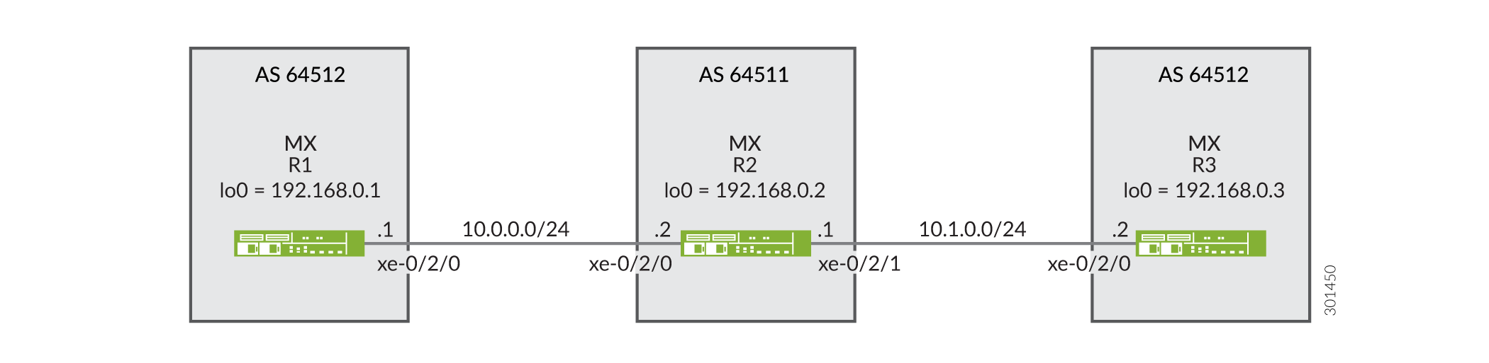
Configuration
CLI Quick Configuration
To quickly configure this example, copy the following commands, paste them into a
text file, remove any line breaks, change any details necessary to match your
network configuration, and then copy and paste the commands into the CLI at the
[edit] hierarchy level.
Device R1
set interfaces xe-0/2/0 description R1-to-R2 set interfaces xe-0/2/0 unit 0 family inet address 10.0.0.1/30 set interfaces lo0 unit 0 family inet address 192.168.0.1/32 set protocols bgp family inet unicast loops 2 set protocols bgp group ext type external set protocols bgp group ext export send-direct set protocols bgp group ext peer-as 64511 set protocols bgp group ext neighbor 10.0.0.2 set policy-options policy-statement send-direct term 1 from protocol direct set policy-options policy-statement send-direct term 1 then accept set routing-options autonomous-system 64512
Device R2
set interfaces xe-0/2/0 description R2-to-R1 set interfaces xe-0/2/0 unit 0 family inet address 10.0.0.2/30 set interfaces xe-0/2/1 description R2-to-R3 set interfaces xe-0/2/1 unit 0 family inet address 10.1.0.1/30 set interfaces lo0 unit 0 family inet address 192.168.0.2/32 set protocols bgp group ext type external set protocols bgp group ext advertise-peer-as set protocols bgp group ext export send-direct set protocols bgp group ext neighbor 10.0.0.1 peer-as 64512 set protocols bgp group ext neighbor 10.1.0.2 peer-as 64512 set policy-options policy-statement send-direct term 1 from protocol direct set policy-options policy-statement send-direct term 1 then accept set routing-options autonomous-system 64511
Device R3
set interfaces xe-0/2/0 description R3-to-R2 set interfaces xe-0/2/0 unit 0 family inet address 10.1.0.2/30 set interfaces lo0 unit 0 family inet address 192.168.0.3/32 set protocols bgp family inet unicast loops 2 set protocols bgp group ext type external set protocols bgp group ext export send-direct set protocols bgp group ext peer-as 64511 set protocols bgp group ext neighbor 10.1.0.1 set policy-options policy-statement send-direct term 1 from protocol direct set policy-options policy-statement send-direct term 1 then accept set routing-options autonomous-system 64512
Procedure
Step-by-Step Procedure
The following example requires that you navigate various levels in the configuration hierarchy. For information about navigating the CLI, see Using the CLI Editor in Configuration Mode in the Junos OS CLI User Guide.
To configure Device R1:
-
Configure the device interfaces.
[edit interfaces] user@R1# set xe-0/2/0 description R1-to-R2 user@R1# set xe-0/2/0 unit 0 family inet address 10.0.0.1/30 user@R1# set lo0 unit 0 family inet address 192.168.0.1/32
-
Configure BGP.
[edit protocols bgp group ext] user@R1# set type external user@R1# set peer-as 64511 user@R1# set neighbor 10.0.0.2
-
Prevent routes from Device R3 from being hidden on Device R1 by including the
loops 2statement.The
loops 2statement means that the local device’s own AS number can appear in the AS path up to one time without causing the route to be hidden. The route is hidden if the local device’s AS number is detected in the path two or more times.[edit protocols bgp family inet unicast] user@R1# set loops 2
-
Configure the routing policy that sends direct routes.
[edit policy-options policy-statement send-direct term 1] user@R1# set from protocol direct user@R1# set then accept
-
Apply the export policy to the BGP peering session with Device R2.
[edit protocols bgp group ext] user@R1# set export send-direct
-
Configure the autonomous system (AS) number.
[edit routing-options ] user@R1# set autonomous-system 64512
Step-by-Step Procedure
To configure Device R2:
-
Configure the device interfaces.
[edit interfaces] user@R2# set xe-0/2/0 description R2-to-R1 user@R2# set xe-0/2/0 unit 0 family inet address 10.0.0.2/30 user@R2# set xe-0/2/1 description R2-to-R3 user@R2# set xe-0/2/1 unit 0 family inet address 10.1.0.1/30 user@R2# set lo0 unit 0 family inet address 192.168.0.2/32
-
Configure BGP.
[edit protocols bgp group ext] user@R2# set type external user@R2# set neighbor 10.0.0.1 peer-as 64512 user@R2# set neighbor 10.1.0.2 peer-as 64512
-
Configure Device R2 to advertise routes learned from one EBGP peer to another EBGP peer in the same AS.
In other words, advertise to Device R1 routes learned from Device R3 (and the reverse), even though Device R1 and Device R3 are in the same AS.
[edit protocols bgp group ext] user@R2# set advertise-peer-as
-
Configure a routing policy that sends direct routes.
[edit policy-options policy-statement send-direct term 1] user@R2# set from protocol direct user@R2# set then accept
-
Apply the export policy.
[edit protocols bgp group ext] user@R2# set export send-direct
-
Configure the AS number.
[edit routing-options] user@R2# set autonomous-system 64511
Results
From configuration mode, confirm your configuration by entering the
show interfaces, show protocols,
show policy-options, and show
routing-options commands. If the output does not display the
intended configuration, repeat the instructions in this example to correct
the configuration.
Device R1
user@R1# show interfaces
xe-0/2/0 {
description R1-to-R2;
unit 0 {
family inet {
address 10.0.0.1/30;
}
}
}
lo0 {
unit 0 {
family inet {
address 192.168.0.1/32;
}
}
}
user@R1# show protocols
bgp {
family inet {
unicast {
loops 2;
}
}
group ext {
type external;
export send-direct;
peer-as 64511;
neighbor 10.0.0.2;
}
}
user@R1# show policy-options
policy-statement send-direct {
    term 1 {
        from protocol direct;
        then accept;
    }
}
user@R1# show routing-options autonomous-system 64512;
Device R2
user@R2# show interfaces
xe-0/2/0 {
description R2-to-R1;
unit 0 {
family inet {
address 10.0.0.2/30;
}
}
}
xe-0/2/1 {
description R2-to-R3;
unit 0 {
family inet {
address 10.1.0.1/30;
}
}
}
lo0 {
unit 0 {
family inet {
address 192.168.0.2/32;
}
}
}
user@R2# show protocols
bgp {
group ext {
type external;
advertise-peer-as;
export send-direct;
neighbor 10.0.0.1 {
peer-as 64512;
}
neighbor 10.1.0.2 {
peer-as 64512;
}
}
}
user@R2# show policy-options
policy-statement send-direct {
term 1 {
from protocol direct;
then accept;
}
}
user@R2# show routing-options autonomous-system 64511;
If you are done configuring the devices, enter commit from
configuration mode.
Verification
Confirm that the configuration is working properly.
Verifying the BGP Routes
Purpose
Make sure that the routing tables on Device R1 and Device R3 contain the expected routes.
Action
-
On Device R2, deactivate the
advertise-peer-asstatement in the BGP configuration.[edit protocols bgp group ext] user@R2# deactivate advertise-peer-as user@R2# commit
-
On Device R3, deactivate the
loopsstatement in the BGP configuration.[edit protocols bgp family inet unicast ] user@R3# deactivate unicast loops user@R3# commit
-
On Device R1, check to see what routes are advertised to Device R2.
user@R1> show route advertising-protocol bgp 10.0.0.2 inet.0: 5 destinations, 6 routes (5 active, 0 holddown, 0 hidden) Prefix Nexthop MED Lclpref AS path * 10.0.0.0/30 Self I * 192.168.0.1/32 Self I
-
On Device R2, check to see what routes are received from Device R1.
user@R2> show route receive-protocol bgp 10.0.0.1 inet.0: 7 destinations, 9 routes (7 active, 0 holddown, 0 hidden) Prefix Nexthop MED Lclpref AS path 10.0.0.0/30 10.0.0.1 64512 I * 192.168.0.1/32 10.0.0.1 64512 I
-
On Device R2, check to see what routes are advertised to Device R3.
user@R2> show route advertising-protocol bgp 10.1.0.2 inet.0: 7 destinations, 9 routes (7 active, 0 holddown, 0 hidden) Prefix Nexthop MED Lclpref AS path * 10.0.0.0/30 Self I * 10.1.0.0/30 Self I * 192.168.0.2/32 Self I
-
On Device R2, activate the
advertise-peer-asstatement in the BGP configuration.[edit protocols bgp group ext] user@R2# activate advertise-peer-as user@R2# commit
-
On Device R2, recheck the routes that are advertised to Device R3.
user@R2> show route advertising-protocol bgp 10.1.0.2 inet.0: 7 destinations, 9 routes (7 active, 0 holddown, 0 hidden) Prefix Nexthop MED Lclpref AS path * 10.0.0.0/30 Self I * 10.1.0.0/30 Self I * 192.168.0.1/32 Self 64512 I * 192.168.0.2/32 Self I * 192.168.0.3/32 10.1.0.2 64512 I
-
On Device R3, check the routes that are received from Device R2.
user@R3> show route receive-protocol bgp 10.1.0.1 inet.0: 5 destinations, 6 routes (5 active, 0 holddown, 0 hidden) Prefix Nexthop MED Lclpref AS path * 10.0.0.0/30 10.1.0.1 64511 I 10.1.0.0/30 10.1.0.1 64511 I * 192.168.0.2/32 10.1.0.1 64511 I
-
On Device R3, activate the
loopsstatement in the BGP configuration.[edit protocols bgp family inet unicast ] user@R3# activate unicast loops user@R3# commit
-
On Device R3, recheck the routes that are received from Device R2.
user@R3> show route receive-protocol bgp 10.1.0.1 inet.0: 6 destinations, 8 routes (6 active, 0 holddown, 1 hidden) Prefix Nexthop MED Lclpref AS path * 10.0.0.0/30 10.1.0.1 64511 I 10.1.0.0/30 10.1.0.1 64511 I * 192.168.0.1/32 10.1.0.1 64511 64512 I * 192.168.0.2/32 10.1.0.1 64511 I
Meaning
First the advertise-peer-as statement and the
loops statement are deactivated so that the default
behavior can be examined. Device R1 sends to Device R2 a route to Device
R1’s loopback interface address, 192.168.0.1/32. Device R2 does not
advertise this route to Device R3. After activating the
advertise-peer-as statement, Device R2 does advertise
the 192.168.0.1/32 route to Device R3. Device R3 does not accept this route
until after the loops statement is activated.
Disabling Attribute Set Messages on Independent AS Domains for BGP Loop Detection
BGP loop detection for a specific route uses the local autonomous system (AS) domain for the
routing instance. By default, all routing instances belong to a single primary
routing instance domain which is configured under the global hierarchy
routing-options. Therefore, BGP loop detection uses the local
ASs configured on all of the routing instances. Depending on your network
configuration, this default behavior can cause routes to be looped and hidden. For
brevity, we will refer to 'local AS' as the AS for a particular routing instance and
'global AS' for the global configuration or primary routing instance.
To limit the local ASs in the primary routing instance, you can configure an independent AS domain for a routing instance. The independent domain is separate from the primary routing instance and keeps the AS paths of the independent domain from being shared with the AS path and the AS path attributes of other domains.
By default, independent domains use transitive path attribute 128 (attribute set) messages to tunnel the independent domain’s BGP attributes through the internal BGP (IBGP) core. However, the attribute set message behavior for independent domains is undesired in many cases. If you only want to configure independent domains to maintain the independence of local ASs in the routing instance, and perform BGP loop detection only for the specified local ASs in the routing instance, you can disable the attribute set messages.
To disable attribute set messages on an independent domain,
include the independent-domain no-attrset statement:
After you specify a routing instance for an independent domain, the local ASs are only associated with that routing instance. That means BGP loop detection uses only the local ASs defined in the routing instance.
See Also
Example: Ignoring the AS Path Attribute When Selecting the Best Path
If multiple BGP routes to the same destination exist, BGP selects the best path based on the route attributes of the paths. One of the route attributes that affects the best-path decision is the length of the AS paths of each route. Routes with shorter AS paths are preferred over those with longer AS paths. Although not typically practical, some scenarios might require that the AS path length be ignored in the route selection process. This example shows how to configure a routing device to ignore the AS path attribute.
Requirements
No special configuration beyond device initialization is required before you configure this example.
Overview
On externally connected routing devices, the purpose of skipping the AS path comparison might be to force an external BGP (EBGP) versus internal BGP (IBGP) decision to remove traffic from your network as soon as possible. On internally connected routing devices, you might want your IBGP-only routers to default to the local externally connected gateway. The local IBGP-only (internal) routers skip the AS path comparison and move down the decision tree to use the closest interior gateway protocol (IGP) gateway (lowest IGP metric). Doing this might be an effective way to force these routers to use a LAN connection instead of their WAN connection.
When you include the as-path-ignore statement
on a routing device in your network, you might need to include it
on all other BGP-enabled devices in your network to prevent routing
loops and convergence issues. This is especially true for IBGP path
comparisons.
In this example, Device R2 is learning about the loopback interface address on Device R4 (10.4.4.4/32) from Device R1 and Device R3. Device R1 is advertising 10.4.4.4/32 with an AS-path of 65001 65005 65004, and Device R3 is advertising 10.4.4.4/32 with an AS-path of 65003 65004. Device R2 selects the path for 10.4.4.4/32 from Device R3 as the best path because the AS path is shorter than the AS path from Device R1.
This example modifies the BGP configuration on Device R2 so that the AS-path length is not used in the best-path selection.
Device R1 has a lower router ID (10.1.1.1) than Device R3 (10.3.3.3). If all other path selection criteria are equal (or, as in this case, ignored), the route learned from Device R1 is used. Because the AS-path attribute is being ignored, the best path is toward Device R1 because of its lower router ID value.
Figure 7 shows the sample topology.
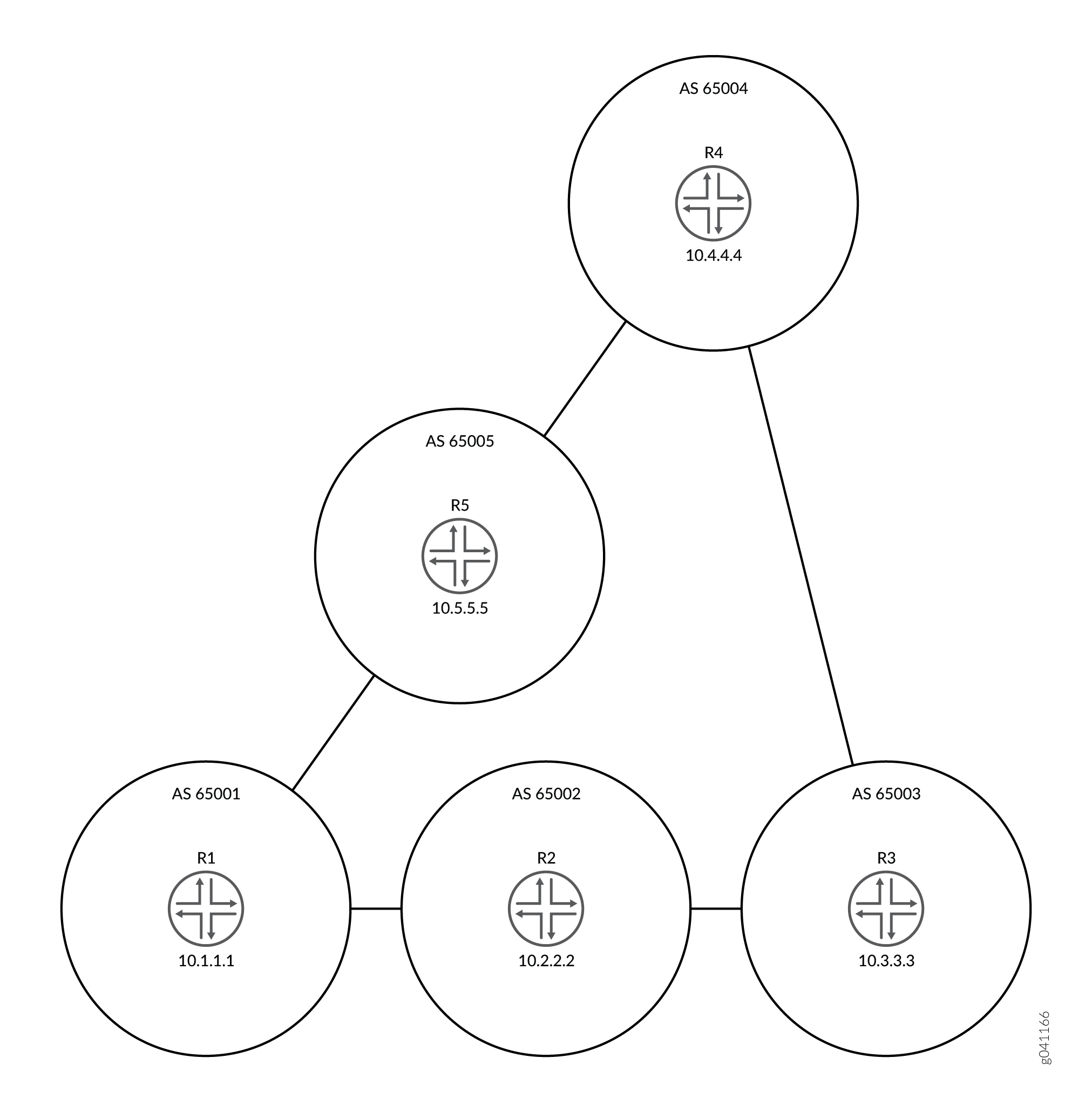
Configuration
CLI Quick Configuration
To quickly configure this example, copy the
following commands, paste them into a text file, remove any line breaks,
change any details necessary to match your network configuration,
and then copy and paste the commands into the CLI at the [edit] hierarchy level.
Device R1
set interfaces fe-1/2/0 unit 1 family inet address 192.168.10.1/24 set interfaces fe-1/2/1 unit 10 family inet address 192.168.50.2/24 set interfaces lo0 unit 1 family inet address 10.1.1.1/32 set protocols bgp group ext type external set protocols bgp group ext export send-direct set protocols bgp group ext export send-static set protocols bgp group ext export send-local set protocols bgp group ext neighbor 192.168.10.2 peer-as 65002set protocols bgp group ext neighbor 192.168.50.1 peer-as 65005 set policy-options policy-statement send-direct term 1 from protocol direct set policy-options policy-statement send-direct term 1 then accept set policy-options policy-statement send-local term 1 from protocol local set policy-options policy-statement send-local term 1 then accept set policy-options policy-statement send-static term 1 from protocol static set policy-options policy-statement send-static term 1 then accept set routing-options static route 192.168.20.0/24 next-hop 192.168.10.2 set routing-options static route 192.168.30.0/24 next-hop 192.168.10.2 set routing-options static route 192.168.40.0/24 next-hop 192.168.50.1 set routing-options router-id 10.1.1.1 set routing-options autonomous-system 65001
Device R2
set interfaces fe-1/2/0 unit 2 family inet address 192.168.10.2/24 set interfaces fe-1/2/1 unit 3 family inet address 192.168.20.2/24 set interfaces lo0 unit 2 family inet address 10.2.2.2/32 set protocols bgp path-selection as-path-ignore set protocols bgp group ext type external set protocols bgp group ext export send-direct set protocols bgp group ext export send-static set protocols bgp group ext export send-local set protocols bgp group ext neighbor 192.168.10.1 peer-as 65001 set protocols bgp group ext neighbor 192.168.20.1 peer-as 65003 set policy-options policy-statement send-direct term 1 from protocol direct set policy-options policy-statement send-direct term 1 then accept set policy-options policy-statement send-local term 1 from protocol local set policy-options policy-statement send-local term 1 then accept set policy-options policy-statement send-static term 1 from protocol static set policy-options policy-statement send-static term 1 then accept set routing-options static route 192.168.50.0/24 next-hop 192.168.10.1 set routing-options static route 192.168.40.0/24 next-hop 192.168.10.1 set routing-options static route 192.168.30.0/24 next-hop 192.168.20.1 set routing-options router-id 10.2.2.2 set routing-options autonomous-system 65002
Device R3
set interfaces fe-1/2/0 unit 4 family inet address 192.168.20.1/24 set interfaces fe-1/2/1 unit 5 family inet address 192.168.30.1/24 set interfaces lo0 unit 3 family inet address 10.3.3.3/32 set protocols bgp group ext type external set protocols bgp group ext export send-direct set protocols bgp group ext export send-static set protocols bgp group ext export send-local set protocols bgp group ext neighbor 192.168.20.2 peer-as 65002 set protocols bgp group ext neighbor 192.168.30.2 peer-as 65004 set policy-options policy-statement send-direct term 1 from protocol direct set policy-options policy-statement send-direct term 1 then accept set policy-options policy-statement send-local term 1 from protocol local set policy-options policy-statement send-local term 1 then accept set policy-options policy-statement send-static term 1 from protocol static set policy-options policy-statement send-static term 1 then accept set routing-options static route 192.168.10.0/24 next-hop 192.168.20.2 set routing-options static route 192.168.50.0/24 next-hop 192.168.20.2 set routing-options static route 192.168.40.0/24 next-hop 192.168.30.2 set routing-options router-id 10.3.3.3 set routing-options autonomous-system 65003
Device R4
set interfaces fe-1/2/0 unit 6 family inet address 192.168.30.2/24
set interfaces fe-1/2/1 unit 7 family inet address 192.168.40.1/24
set interfaces lo0 unit 4 family inet address 10.4.4.4/32
set protocols bgp group ext type external
set protocols bgp group ext export send-direct
set protocols bgp group ext export send-static
set protocols bgp group ext export send-local
set protocols bgp group ext neighbor 192.168.30.1 peer-as 65003
set protocols bgp group ext neighbor 192.168.40.2 peer-as 65005
set policy-options policy-statement send-direct term 1 from protocol direct
set policy-options policy-statement send-direct term 1 then accept
set policy-options policy-statement send-local term 1 from protocol local
set policy-options policy-statement send-local term 1 then accept
set policy-options policy-statement send-static term 1 from protocol static
set policy-options policy-statement send-static term 1 then accept
set routing-options static route 192.168.10.0/24 next-hop 192.168.40.2
set routing-options static route 192.168.50.0/24 next-hop 192.168.40.2
set routing-options static route 192.168.40.0/24 next-hop 192.168.30.1
set routing-options router-id 10.4.4.4
set routing-options autonomous-system 65004
Device R5
set interfaces fe-1/2/0 unit 8 family inet address 192.168.40.2/24 set interfaces fe-1/2/1 unit 9 family inet address 192.168.50.1/24 set interfaces lo0 unit 5 family inet address 10.5.5.5/32 set protocols bgp group ext type external set protocols bgp group ext export send-direct set protocols bgp group ext export send-static set protocols bgp group ext export send-local set protocols bgp group ext neighbor 192.168.40.1 peer-as 65004 set protocols bgp group ext neighbor 192.168.50.2 peer-as 65001 set policy-options policy-statement send-direct term 1 from protocol direct set policy-options policy-statement send-direct term 1 then accept set policy-options policy-statement send-local term 1 from protocol local set policy-options policy-statement send-local term 1 then accept set policy-options policy-statement send-static term 1 from protocol static set policy-options policy-statement send-static term 1 then accept set routing-options static route 192.168.10.0/24 next-hop 192.168.50.2 set routing-options static route 192.168.20.0/24 next-hop 192.168.50.2 set routing-options static route 192.168.30.0/24 next-hop 192.168.40.1 set routing-options router-id 10.5.5.5 set routing-options autonomous-system 65005
Configuring Device R2
Step-by-Step Procedure
The following example requires you to navigate various levels in the configuration hierarchy. For information about navigating the CLI, see Using the CLI Editor in Configuration Mode in the Junos OS CLI User Guide.
To configure Device R2:
-
Configure the interfaces.
[edit interfaces] user@R2# set fe-1/2/0 unit 2 family inet address 192.168.10.2/24 user@R2# set fe-1/2/1 unit 3 family inet address 192.168.20.2/24 user@R2# set lo0 unit 2 family inet address 10.2.2.2/32
-
Configure EBGP.
[edit protocols bgp group ext] user@R2# set type external user@R2# set export send-direct user@R2# set export send-static user@R2# set export send-local user@R2# set neighbor 192.168.10.1 peer-as 65001 user@R2# set neighbor 192.168.20.1 peer-as 65003
-
Configure the autonomous system (AS) path attribute to be ignored in the Junos OS path selection algorithm.
[edit protocols bgp] user@R2# set path-selection as-path-ignore
-
Configure the routing policy.
[edit policy-options] user@R2# set policy-statement send-direct term 1 from protocol direct user@R2# set policy-statement send-direct term 1 then accept user@R2# set policy-statement send-local term 1 from protocol local user@R2# set policy-statement send-local term 1 then accept user@R2# set policy-statement send-static term 1 from protocol static user@R2# set policy-statement send-static term 1 then accept
-
Configure some static routes.
[edit routing-options static] user@R2# set route 192.168.50.0/24 next-hop 192.168.10.1 user@R2# set route 192.168.40.0/24 next-hop 192.168.10.1 user@R2# set route 192.168.30.0/24 next-hop 192.168.20.1
-
Configure the autonomous system (AS) number and the router ID.
[edit routing-options] user@R2# set router-id 10.2.2.2 user@R2# set autonomous-system 65002
Results
From configuration mode, confirm your configuration
by entering the show interfaces, show policy-options, show protocols, and show routing-options commands.
If the output does not display the intended configuration, repeat
the instructions in this example to correct the configuration.
user@R2# show interfaces
fe-1/2/0 {
unit 2 {
family inet {
address 192.168.10.2/24;
}
}
}
fe-1/2/1 {
unit 3 {
family inet {
address 192.168.20.2/24;
}
}
}
lo0 {
unit 2 {
family inet {
address 10.2.2.2/32;
}
}
}user@R2# show policy-options
policy-statement send-direct {
term 1 {
from protocol direct;
then accept;
}
}
policy-statement send-local {
term 1 {
from protocol local;
then accept;
}
}
policy-statement send-static {
term 1 {
from protocol static;
then accept;
}
}user@R2# show protocols
bgp {
path-selection as-path-ignore;
group ext {
type external;
export [ send-direct send-static send-local ];
neighbor 192.168.10.1 {
peer-as 65001;
}
neighbor 192.168.20.1 {
peer-as 65003;
}
}
}user@R2# show routing-options
static {
route 192.168.50.0/24 next-hop 192.168.10.1;
route 192.168.40.0/24 next-hop 192.168.10.1;
route 192.168.30.0/24 next-hop 192.168.20.1;
}
router-id 10.2.2.2;
autonomous-system 65002;If you are done configuring the device, enter commit from configuration mode. Repeat the configuration on the other devices in the network, changing the interface names and IP addresses, as needed.
Verification
Confirm that the configuration is working properly.
Checking the Neighbor Status
Purpose
Make sure that from Device R2, the active path to get to AS 4 is through AS 65001 and AS 65005, not through AS 65003.
To verify the functionality of the as-path-ignore statement, you might need to run the restart routing command
to force reevaluation of the active path. This is because for BGP,
if both paths are external, the Junos OS behavior is to prefer the
currently active path. This behavior helps to minimize route-flapping.
Use caution when restarting the routing protocol process in a production
network.
Action
From operational mode, enter the
restart routing command.
user@R2> restart routing Routing protocols process started, pid 49396
From operational mode, enter the show route 10.4.4.4 protocol bgp command.
user@R2> show route 10.4.4.4 protocol bgp
inet.0: 12 destinations, 25 routes (12 active, 0 holddown, 4 hidden)
+ = Active Route, - = Last Active, * = Both
10.4.4.4/32 *[BGP/170] 00:00:12, localpref 100
AS path: 65001 65005 65004 I
> to 192.168.10.1 via fe-1/2/0.2
[BGP/170] 00:00:08, localpref 100
AS path: 65003 65004 I
> to 192.168.20.1 via fe-1/2/1.3Meaning
The asterisk (*) is next to the path learned from R1, meaning that this is the active path. The AS path for the active path is 65001 65005 65004, which is longer than the AS path (65003 65004) for the nonactive path learned from Router R3.
Understanding Private AS Number Removal from AS Paths
By default, when BGP advertises AS paths to remote systems, it includes all AS numbers, including private AS numbers. You can configure the software so that it removes private AS numbers from AS paths. Doing this is useful when any of the following circumstances are true:
A remote AS for which you provide connectivity is multihomed, but only to the local AS.
The remote AS does not have an officially allocated AS number.
It is not appropriate to make the remote AS a confederation member AS of the local AS.
Most companies acquire their own AS number. Some companies also
use private AS numbers to connect to their public AS network. These
companies might use a different private AS number for each region
in which their company does business. In any implementation, announcing
a private AS number to the Internet must be avoided. Service providers
can use the remove-private statement to prevent advertising
private AS numbers to the Internet.
In an enterprise scenario, suppose that you have multiple AS
numbers in your company, some of which are private AS numbers, and
one with a public AS number. The one with a public AS number has a
direct connection to the service provider. In the AS that connects
directly to the service provider, you can use the remove-private statement to filter out any private AS numbers in the advertisements
that are sent to the service provider.
The AS numbers are stripped from the AS path starting at the left end of the AS path (the end where AS paths have been most recently added). The routing device stops searching for private ASs when it finds the first nonprivate AS or a peer’s private AS. If the AS path contains the AS number of the external BGP (EBGP) neighbor, BGP does not remove the private AS number.
As of Junos OS 10.0R2 and later, if there is a need to
send prefixes to an EBGP peer that has an AS number that matches an
AS number in the AS path, consider using the as-override statement instead of the remove-private statement.
The operation takes place after any confederation member ASs have already been removed from the AS path, if applicable.
The software is preconfigured with knowledge of the set of AS numbers that is considered private, a range that is defined in the Internet Assigned Numbers Authority (IANA) assigned numbers document. The set of 16 bit AS numbers reserved as private are in the range from 64,512 through 65,534, inclusive. The 32 bit AS numbers reserved as private are in the range from 4,200,000,000 through 4,294,967,294 inclusive.
See Also
Example: Removing Private AS Numbers from AS Paths
This example demonstrates the removal of a private AS number from the advertised AS path to avoid announcing the private AS number to the Internet.
Requirements
No special configuration beyond device initialization is required before you configure this example.
Overview
Service providers and enterprise networks use the
remove-private
statement to prevent advertising private AS numbers to the Internet. The
remove-private statement works in the outbound direction. You
configure the remove-private statement on a device that has a
public AS number and that is connected to one or more devices that have private AS
numbers. Generally, you would not configure this statement on a device that has a
private AS number.
Figure 8 shows the sample topology.
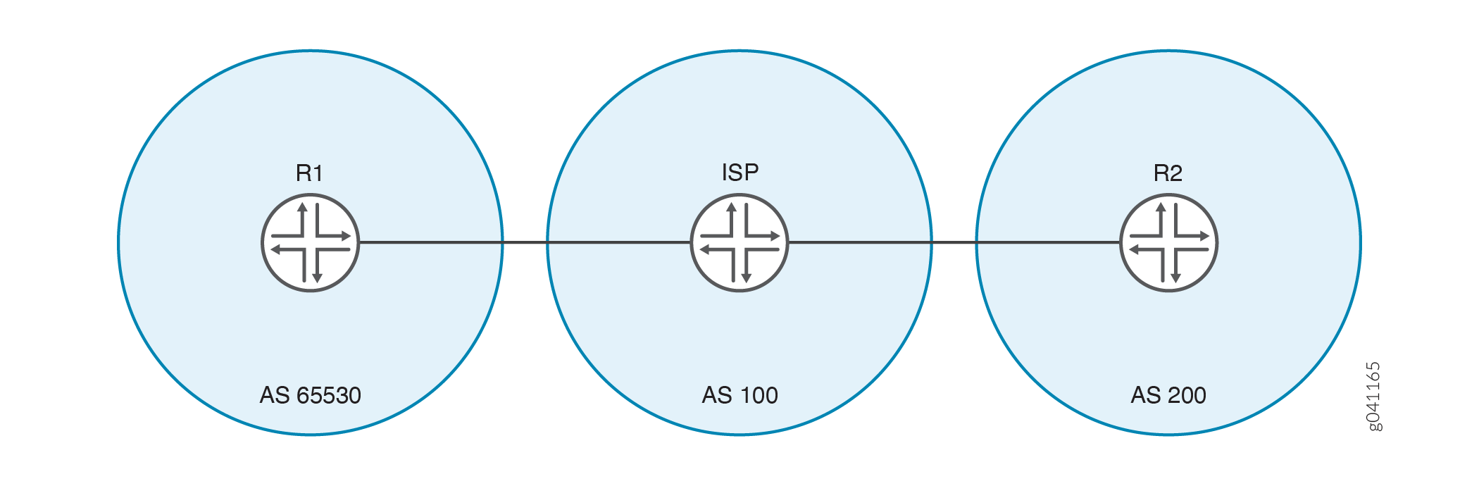
In this example, Device R1 is connected to its service provider using private AS
number 65530. The example shows the
remove-private statement configured on Device ISP to prevent
Device R1’s private AS number from being announced to Device R2. Device R2 sees only
the AS number of the service provider.
Adding or deleting the BGP option remove-private will cause the
affected BGP peering sessions to flap.
Configuration
CLI Quick Configuration
To quickly configure this example, copy the following commands, paste them into a
text file, remove any line breaks, change any details necessary to match your
network configuration, and then copy and paste the commands into the CLI at the
[edit] hierarchy level.
Device R1
set interfaces fe-1/2/0 unit 1 family inet address 192.168.10.1/24
set interfaces lo0 unit 1 family inet address 10.10.10.1/32
set protocols bgp group ext type external
set protocols bgp group ext export send-direct
set protocols bgp group ext export send-static
set protocols bgp group ext peer-as 100
set protocols bgp group ext neighbor 192.168.10.10
set policy-options policy-statement send-direct term 1 from protocol direct
set policy-options policy-statement send-direct term 1 then accept
set policy-options policy-statement send-static term 1 from protocol static
set policy-options policy-statement send-static term 1 then accept
set routing-options static route 192.168.20.0/24 next-hop 192.168.10.10
set routing-options autonomous-system 65530Device ISP
set interfaces fe-1/2/0 unit 2 family inet address 192.168.10.10/24 set interfaces fe-1/2/1 unit 3 family inet address 192.168.20.20/24 set interfaces lo0 unit 2 family inet address 10.10.0.1/32 set protocols bgp group ext type external set protocols bgp group ext neighbor 192.168.10.1 peer-as 65530 set protocols bgp group ext neighbor 192.168.20.1 remove-private set protocols bgp group ext neighbor 192.168.20.1 peer-as 200 set routing-options autonomous-system 100
Device R2
set interfaces fe-1/2/0 unit 4 family inet address 192.168.20.1/24 set interfaces lo0 unit 3 family inet address 10.10.20.1/32 set protocols bgp group ext type external set protocols bgp group ext export send-direct set protocols bgp group ext export send-static set protocols bgp group ext peer-as 100 set protocols bgp group ext neighbor 192.168.20.20 set policy-options policy-statement send-direct term 1 from protocol direct set policy-options policy-statement send-direct term 1 then accept set policy-options policy-statement send-static term 1 from protocol static set policy-options policy-statement send-static term 1 then accept set routing-options static route 192.168.10.0/24 next-hop 192.168.20.20 set routing-options autonomous-system 200
Device ISP
Step-by-Step Procedure
The following example requires you to navigate various levels in the configuration hierarchy. For information about navigating the CLI, see Using the CLI Editor in Configuration Mode in the Junos OS CLI User Guide.
To configure Device ISP:
-
Configure the interfaces.
[edit interfaces] user@ISP# set fe-1/2/0 unit 2 family inet address 192.168.10.10/24 user@ISP# set fe-1/2/1 unit 3 family inet address 192.168.20.20/24 user@ISP# set lo0 unit 2 family inet address 10.10.0.1/32
-
Configure EBGP.
[edit protocols bgp group ext] user@ISP# set type external user@ISP# set neighbor 192.168.10.1 peer-as 65530 user@ISP# set neighbor 192.168.20.1 peer-as 200
-
For the neighbor in autonomous system (AS) 200 (Device R2), remove private AS numbers from the advertised AS paths.
[edit protocols bgp group ext] user@ISP# set neighbor 192.168.20.1 remove-private
-
Configure the AS number.
[edit routing-options] user@ISP# set autonomous-system 100
Results
From configuration mode, confirm your configuration by entering the
show interfaces, show protocols, and
show
                            routing-options
commands. If the output does not
display the intended configuration, repeat the instructions in this example
to correct the configuration.
user@ISP# show interfaces
fe-1/2/0 {
unit 2 {
family inet {
address 192.168.10.10/24;
}
}
}
fe-1/2/1 {
unit 3 {
family inet {
address 192.168.20.20/24;
}
}
}
lo0 {
unit 2 {
family inet {
address 10.10.0.1/32;
}
}
}
user@ISP# show protocols
bgp {
group ext {
type external;
neighbor 192.168.10.1 {
peer-as 65530;
}
neighbor 192.168.20.1 {
remove-private;
peer-as 200;
}
}
}user@ISP# show routing-options autonomous-system 100;
If you are done configuring the device, enter commit from configuration mode. Repeat the configuration on Device R1 and Device R2, changing the interface names and IP address, as needed, and adding the routing policy configuration.
Verification
Confirm that the configuration is working properly.
- Checking the Neighbor Status
- Checking the Routing Tables
- Checking the AS Path When the remove-private Statement Is Deactivated
Checking the Neighbor Status
Purpose
Make sure that Device ISP has the remove-private setting enabled in its neighbor session with Device R2.
Action
From operational mode, enter the show bgp neighbor
192.168.20.1 command.
user@ISP> show bgp neighbor 192.168.20.1
Peer: 192.168.20.1+179 AS 200 Local: 192.168.20.20+60216 AS 100
Type: External State: Established Flags: <ImportEval Sync>
Last State: OpenConfirm Last Event: RecvKeepAlive
Last Error: None
Options: <Preference RemovePrivateAS PeerAS Refresh>
Holdtime: 90 Preference: 170
Number of flaps: 0
Peer ID: 10.10.20.1 Local ID: 10.10.0.1 Active Holdtime: 90
Keepalive Interval: 30 Peer index: 0
BFD: disabled, down
Local Interface: fe-1/2/1.3
NLRI for restart configured on peer: inet-unicast
NLRI advertised by peer: inet-unicast
NLRI for this session: inet-unicast
Peer supports Refresh capability (2)
Stale routes from peer are kept for: 300
Peer does not support Restarter functionality
NLRI that restart is negotiated for: inet-unicast
NLRI of received end-of-rib markers: inet-unicast
NLRI of all end-of-rib markers sent: inet-unicast
Peer supports 4 byte AS extension (peer-as 200)
Peer does not support Addpath
Table inet.0 Bit: 10001
RIB State: BGP restart is complete
Send state: in sync
Active prefixes: 1
Received prefixes: 3
Accepted prefixes: 2
Suppressed due to damping: 0
Advertised prefixes: 1
Last traffic (seconds): Received 10 Sent 16 Checked 55
Input messages: Total 54 Updates 3 Refreshes 0 Octets 1091
Output messages: Total 54 Updates 1 Refreshes 0 Octets 1118
Output Queue[0]: 0Meaning
The RemovePrivateAS option shows that Device ISP has the
expected setting.
Checking the Routing Tables
Purpose
Make sure that the devices have the expected routes and AS paths.
Action
From operational mode, enter the show route protocol bgp
command.
user@R1> show route protocol bgp
inet.0: 5 destinations, 5 routes (5 active, 0 holddown, 0 hidden)
+ = Active Route, - = Last Active, * = Both
10.10.20.1/32 *[BGP/170] 00:28:57, localpref 100
AS path: 100 200 I
> to 192.168.10.10 via fe-1/2/0.1user@ISP> show route protocol bgp
inet.0: 7 destinations, 11 routes (7 active, 0 holddown, 2 hidden)
+ = Active Route, - = Last Active, * = Both
10.10.10.1/32 *[BGP/170] 00:29:40, localpref 100
AS path: 65530 I
> to 192.168.10.1 via fe-1/2/0.2
10.10.20.1/32 *[BGP/170] 00:29:36, localpref 100
AS path: 200 I
> to 192.168.20.1 via fe-1/2/1.3
192.168.10.0/24 [BGP/170] 00:29:40, localpref 100
AS path: 65530 I
> to 192.168.10.1 via fe-1/2/0.2
192.168.20.0/24 [BGP/170] 00:29:36, localpref 100
AS path: 200 I
> to 192.168.20.1 via fe-1/2/1.3user@R2> show route protocol bgp
inet.0: 5 destinations, 5 routes (5 active, 0 holddown, 0 hidden)
+ = Active Route, - = Last Active, * = Both
10.10.10.1/32 *[BGP/170] 00:29:53, localpref 100
AS path: 100 I
> to 192.168.20.20 via fe-1/2/0.4Meaning
Device ISP has the private AS number 65530 in its AS path to Device R1. However, Device ISP does not advertise this private AS number to Device R2. This is shown in the routing table of Device R2. Device R2’s path to Device R1 contains only the AS number for Device ISP.
Checking the AS Path When the remove-private Statement Is Deactivated
Purpose
Verify that without the remove-private statement, the
private AS number appears in Device R2’s routing table.
Action
From configuration mode on Device ISP, enter the deactivate
remove-private command and then recheck the routing table on
Device R2.
[protocols bgp group ext neighbor 192.168.20.1] user@ISP# deactivate remove-private user@ISP# commit
user@R2> show route protocol bgp
inet.0: 5 destinations, 5 routes (5 active, 0 holddown, 0 hidden)
+ = Active Route, - = Last Active, * = Both
10.10.10.1/32 *[BGP/170] 00:00:54, localpref 100
AS path: 100 65530 I
> to 192.168.20.20 via fe-1/2/0.4Meaning
Private AS number 65530 appears in Device R2’s AS path to Device R1.
Change History Table
Feature support is determined by the platform and release you are using. Use Feature Explorer to determine if a feature is supported on your platform.