SIP ALG
The Session Initiation Protocol (SIP) is a signaling protocol for initiating, modifying, and terminating multimedia sessions over the internet. SIP supports single-media and multi-media sessions.
Understanding the SIP ALG
Session Initiation Protocol (SIP) is an Internet Engineering Task Force (IETF)-standard protocol for initiating, modifying, and terminating multimedia sessions over the Internet. Such sessions might include conferencing, telephony, or multimedia, with features such as instant messaging and application-level mobility in network environments.
Junos OS supports SIP as a service, allowing and denying it based on a policy that you configure. SIP is a predefined service in Junos OS and uses port 5060 as the destination port.
One of SIP’s function is to distribute session-description information, and during the session, to negotiate and modify the parameters of the session. SIP is also used to terminate a multimedia session, signal a call establishment, provide failure indication, and provide methods for endpoint registration.
Session-description information is included in INVITE and 200-OK messages or 200-OK and ACK messages and indicates the multimedia type of the session; for example, whether it is voice or video. Although SIP can use different description protocols to describe the session, the Juniper Networks SIP Application Layer Gateway (ALG) supports only the Session Description Protocol (SDP).
SDP provides information that a system can use to join a multimedia session. SDP might include information such as IP addresses, port numbers, times, and dates. Note that the IP address and port number in the SDP header (the c= and m= fields, respectively) are the address and port where the client wants to receive the media streams and not the IP address and port number from which the SIP request originates (although they can be the same).
SIP messages consist of requests from a client to a server and responses to the requests from a server to a client with the purpose of establishing a session (or a call). A user agent (UA) is an application that runs at the endpoints of the call and consists of two parts:
-
user agent client (UAC), which sends SIP requests on behalf of the user
-
user agent server (UAS), which listens to the responses and notifies the user when they arrive
UAC and UAS are defined in relation to the role a particular agent is playing in a negotiation.
Examples of UAs are SIP proxy servers and phones.
This topic contains the following sections:
SIP ALG Operation
There are two types of SIP traffic, the signaling and the media stream. SIP signaling traffic consists of request and response messages between client and server and uses transport protocols such as UDP or TCP. The media stream carries the data (audio data, for example) using transport protocols.
Starting in Junos OS Release 12.3X48-D25 and Junos OS Release 17.3R1, the SIP ALG supports TCP. TCP support over the SIP ALG reduces traffic to the server by eliminating the need to reregister or refresh the server frequently.
By default, Junos OS supports SIP signaling messages on port 5060. You can configure the port by creating a policy that permits SIP service, and the software filters SIP signaling traffic like any other type of traffic, permitting or denying it. The media stream, however, uses dynamically assigned port numbers that can change several times during the course of a call. Without fixed ports, it is insecure to create a static policy to control media traffic. In this case, the device invokes the SIP ALG. The device transport ports used for the media sessions are not known in advance; however, the ports used for the SIP negotiation are well-known (or predefined). The ALG registers interest in packets from the control session, which it can easily distinguish from the other packets, and inspects the negotiation for the transport information used for the media session (both IP addresses and ports).
The SIP ALG creates a pinhole when it determines a matching IP, port, transport address, and protocol, which are identified with whatever information is known at the time when the pinhole is opened.
The SIP ALG monitors SIP transactions and dynamically creates and manages pinholes based on the information it extracts from these transactions. The Juniper Networks SIP ALG supports all SIP methods and responses. You can allow SIP transactions to traverse the Juniper Networks firewall by creating a static policy that permits SIP service. If the policy is configured to inspect SIP traffic (or, more appropriately, if the policy sends some traffic to the SIP ALG for inspection), the allowed actions are to permit the traffic (in which case the appropriate pinholes are opened) or to deny the traffic.
The SIP ALG intercepts SIP messages that contain SDP and, using a parser, extracts the information it requires to create pinholes. The SIP ALG examines the SDP portion of the packet, and a parser extracts information such as IP addresses and port numbers, which the SIP ALG records in a pinhole table. The SIP ALG uses the IP addresses and port numbers recorded in the pinhole table to open pinholes and allow media streams to traverse the device.
When the device is performing NAT, the transport addresses that the UAs employ are incorrect. The SIP ALG modifies the transport addresses based on the translated ports and addresses allocated by the device translating network addresses. When SDP is encrypted, the device cannot either extract or modify the contents of the message and therefore cannot correct the transport addresses. To provide a workaround, the STUN protocol has been deployed (requiring NAT devices to do some form of cone-NAT), which allows the clients to determine the translated addresses and use those newly discovered addresses in the SDP messages.
NEC SIP products are conditionally supported.
SDP Session Descriptions
An SDP session description is a well-defined format for conveying sufficient information to discover and participate in a multimedia session. A session is described by a series of attribute/value pairs, one per line. The attribute names are single characters, followed by =, and a value. Optional values are specified with =*. Values are either an ASCII string, or a sequence of specific types separated by spaces. Attribute names are only unique within the associated syntactic construct, such as within the session, time, or media only.
In the SDP session description, the media-level information begins with the m= field.
Of the many fields in the SDP description, two are particularly useful to the SIP ALG because they contain Transport Layer information.
-
c=for connection informationThis field can appear at the session or media level. It appears in this format:
c=<network-type><address-type><connection-address>
Junos OS supports only “IN” (for Internet) as the network type, “IPv4” as the address type, and a unicast IP address or domain name as the destination (connection) IP address. Starting in Junos OS Release 15.1X49-D40 and Junos OS Release 17.3R1, the “IPv6” address type is also supported.
If the destination IP address is a unicast IP address, the SIP ALG creates pinholes using the IP address and port numbers specified in the media description field m=.
-
m=for media announcementThis field appears at the media level and contains the description of the media. It appears in this format:
m=<media><port><transport><fmt list>
Currently, Junos OS supports ”RTP” as the Application Layer transport protocol. The port number indicates the destination port of the media stream (the origin is allocated by the remote UA). The format list (fmt list) provides information on the Application Layer protocol that the media uses.
The software opens ports only for RTP and Real-Time Control Protocol (RTCP). Every RTP session has a corresponding RTCP session. Therefore, whenever a media stream uses RTP, the SIP ALG must reserve ports (create pinholes) for both RTP and RTCP traffic. By default, the port number for RTCP is one higher than the RTP port number.
Pinhole Creation
Each pinhole (one for RTP traffic and the other for RTCP traffic) share the same destination IP address. The IP address comes from the c= field in the SDP session description. Because the c= field can appear in either the session-level or the media-level portion of the SDP session description, the parser determines the IP address based on the following rules (in accordance with SDP conventions):
-
First, the SIP ALG parser looks for a c= field containing an IP address in the media level. If there is such a field, the parser extracts that IP address, and the SIP ALG uses that address to create a pinhole for the media.
-
If there is no c= field in the media level, the SIP ALG parser extracts the IP address from the c= field in the session level, and the SIP ALG uses that IP address to create a pinhole for the media. If the session description does not contain a c= field in either level, this indicates an error in the protocol stack, and the device drops the packet and logs the event.
The SIP ALG also opens pinholes for signal traffic. These signal pinholes are useful after the previous signal session timeout, and they are also useful for the signal traffic sent to a third-party address that does not match with the previous signal session. The SIP ALG signal pinholes never age out, unlike RTP or RTCP pinholes, where only the destination IP and destination port are specified.
The SIP ALG opens signal pinholes for following headers, if needed:
-
VIA
-
CONTACT
-
ROUTE
-
RECORD-ROUTE
The SIP ALG needs the following information to create a pinhole. This information either comes from the SDP session description or from the SIP headers (as listed above).
-
Protocol—UDP or TCP.
-
Source IP—Unknown.
-
Source port—Unknown.
-
Destination IP—The parser extracts the destination IP address from the c= field at the media or session level.
-
Destination port—The parser extracts the destination port number for RTP from the m= field in the media level and calculates the destination port number for RTCP using the following formula:
RTP port number + one
-
Lifetime—This value indicates the length of time (in seconds) during which a pinhole is open to allow a packet through. A packet must go through the pinhole before the lifetime expires. When the lifetime expires, the SIP ALG removes the pinhole.
When a packet goes through the pinhole within the lifetime period, immediately afterwards the SIP ALG removes the pinhole for the direction from which the packet came.
Figure 1 describes a call setup between two SIP clients and how the SIP ALG creates pinholes to allow RTP and RTCP traffic. The illustration assumes that the device has a policy that permits SIP, thus opening port 5060 for SIP signaling messages.
Figure 1: SIP ALG Call Setup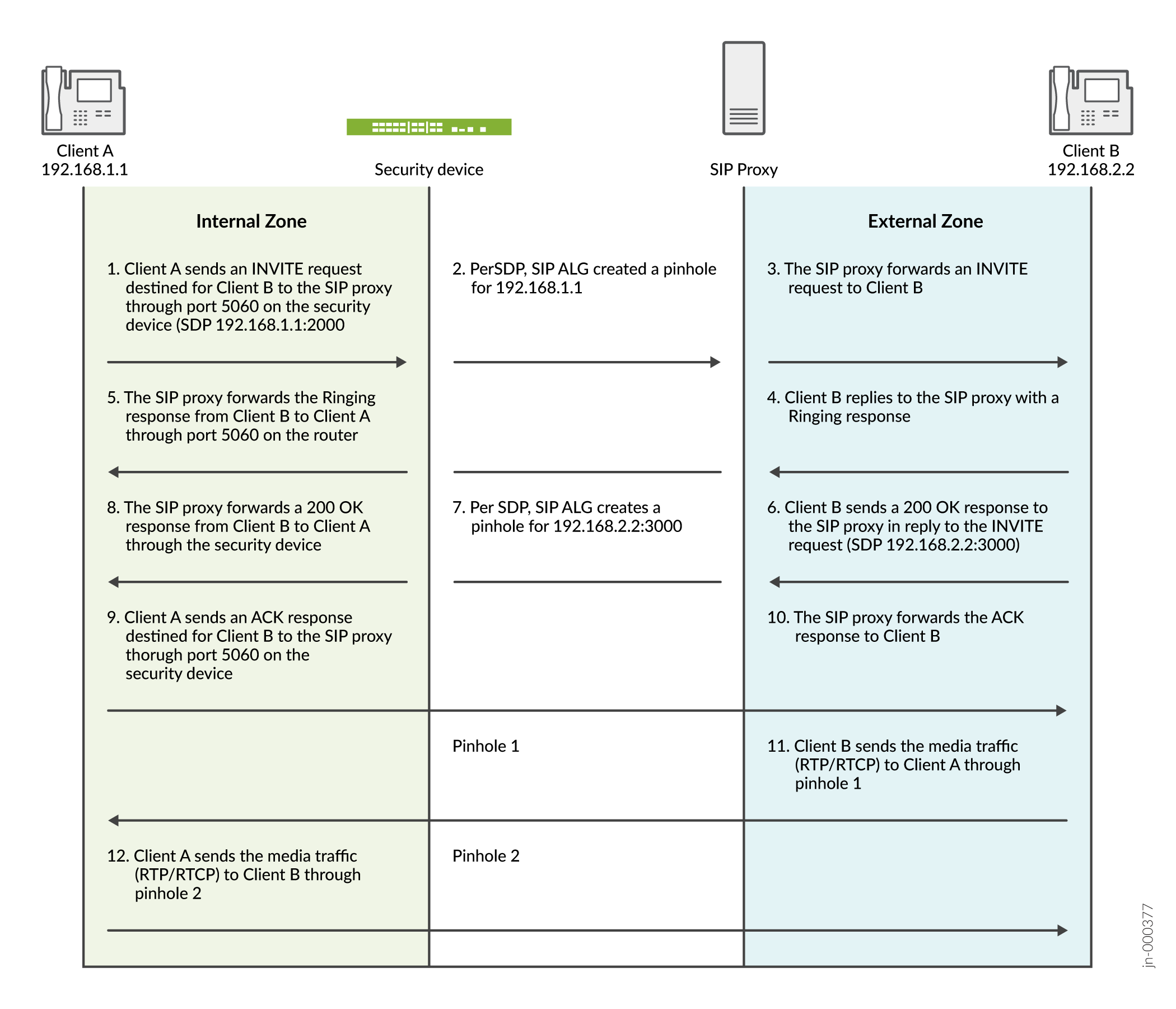
The SIP ALG does not create pinholes for RTP and RTCP traffic when the destination IP address is 0.0.0.0, which indicates that the session is on hold. To put a session on hold during a telephone communication, for example, Client A sends Client B a SIP message in which the destination IP address is 0.0.0.0. Doing so indicates to Client B that it should not send any media until further notice. If Client B sends media anyway, the device drops the packets.
- Understanding IPv6 Support for SIP ALG
- Understanding Scaling Busy Lamp Field Support for the UDP-Based SIP ALG
- Understanding SIP ALG Request Methods
- SIP ALG Configuration Overview
- Understanding SIP ALG DoS Attack Protection
- Understanding SIP ALG Unknown Message Types
- Understanding SIP ALG Call Duration and Timeouts
Understanding IPv6 Support for SIP ALG
IPv6 is supported on the SIP ALG along with NAT-PT mode and NAT64 address translation.
The SIP ALG processes the IPv6 address in the same way it processes the IPv4 address for updating the payload if NAT is configured and opening pinholes for future traffic.
Special processing occurs for the following formats:
-
IPv6 in SIP URIs—The SIP URI looks the same as a URI with IPv4 addresses. As in all URIs, an IPv6 address is enclosed in square brackets. The IPv6 address blocks are separated by colons. In many notations, a colon separates the hostname or IP address from the protocol port. To parse the full IPv6 address and separate the port, the address is encapsulated within square brackets
-
IPv6 in SDP—IPv6 addresses in the Session Description Protocol (SDP) have the IP6 marker.
-
The SIP ALG with IPv6 support has the following limitation:
-
When NAT64 with persistent NAT is implemented, the SIP ALG adds the NAT translation to the persistent NAT binding table if NAT is configured on the Address of Record (AOR). Because persistent NAT cannot duplicate the address configured, coexistence of NAT66 and NAT64 configured on the same address is not supported.
Only one binding is created for the same source IP address.
-
Understanding Scaling Busy Lamp Field Support for the UDP-Based SIP ALG
Busy lamp field (BLF) is a light on an IP phone that indicates whether another extension connected to the same private branch exchange (PBX) is busy or not. You can manually configure the BLF by using a Web interface. When BLF is configured, the phone subscribes to a resource list available on the IP PBX to be notified of status information for other extensions. BLF works through the Session Initiation Protocol (SIP) and uses the SUBSCRIBE and NOTIFY messages. Usually, the phone is the subscriber and the IP PBX is the notifier.
When a phone is registered to the IP PBX, the IP PBX notifies the phone of the state of the resource list. For example, if the resource list is huge, the body of the NOTIFY message will also be huge. Because the SIP ALG supports only 3000-byte SIP messages, it bypasses the huge NOTIFY message. If there are too many instances of BLF in the message body, the payload will not be changed and the gate will not be opened.
Starting with Junos OS Release 12.3X48-D15 and Junos OS Release 17.3R1, the SIP ALG supports 65,000-byte SIP messages on the UDP protocol. In the scaling BLF application, if every instance is around 500 bytes, the SIP ALG supports 100 instances in one SIP UDP message.
BLF support for the UDP-based SIP ALG includes the following features:
-
The device can send and receive 65,000-byte SIP messages.
-
The SIP ALG can parse the 65,000-byte SIP messages and open the pinhole, if required.
-
The SIP ALG regenerates the new jumbo SIP message if NAT is configured and the payload is changed.
Understanding SIP ALG Request Methods
The Session Initiation Protocol (SIP) transaction model includes a number of request and response messages, each of which contains a method field that denotes the purpose of the message.
Junos OS supports the following method types and response codes:
-
INVITE—A user sends an INVITE request to invite another user to participate in a session. The body of an INVITE request can contain the description of the session.
-
ACK—The user from whom the INVITE originated sends an ACK request to confirm reception of the final response to the INVITE request. If the original INVITE request did not contain the session description, the ACK request must include it.
-
OPTIONS—The User Agent (UA) obtains information about the capabilities of the SIP proxy. A server responds with information about what methods, session description protocols, and message encoding it supports.
-
BYE—A user sends a BYE request to abandon a session. A BYE request from either user automatically terminates the session.
-
CANCEL—A user sends a CANCEL request to cancel a pending INVITE request. A CANCEL request has no effect if the SIP server processing the INVITE had sent a final response for the INVITE before it received the CANCEL.
-
REGISTER—A user sends a REGISTER request to a SIP registrar server to inform it of the current location of the user. A SIP registrar server records all the information it receives in REGISTER requests and makes this information available to any SIP server attempting to locate a user.
-
Info—Used to communicate mid-session signaling information along the signaling path for the call.
-
Subscribe—Used to request current state and state updates from a remote node.
-
Notify—Sent to inform subscribers of changes in state to which the subscriber has a subscription.
-
Refer—Used to refer the recipient (identified by the Request-URI) to a third party by the contact information provided in the request.
For example, if user A in a private network refers user B, in a public network, to user C, who is also in the private network, the SIP Application Layer Gateway (ALG) allocates a new IP address and port number for user C so that user C can be contacted by user B. If user C is registered with a registrar, however, its port mapping is stored in the ALG Network Address Translation (NAT) table and is reused to perform the translation.
-
Update—Used to open pinhole for new or updated SDP information. The Via:, From:, To:, Call-ID:, Contact:, Route:, and Record-Route: header fields are modified.
-
1xx, 202, 2xx, 3xx, 4xx, 5xx, 6xx Response Codes—Used to indicate the status of a transaction. Header fields are modified.
SIP ALG Configuration Overview
The Session Initiation Protocol Application Layer Gateway (SIP ALG) is disabled by default on SRX device—it should be enabled using the CLI if required. On other devices, it is enabled by default. To fine-tune SIP ALG operations use the following instructions:
-
Control SIP call activity. For instructions, see Example: Setting SIP ALG Call Duration and Timeouts.
-
Protect the SIP proxy server from denial-of-service (DoS) flood attacks. For instructions, see Example: Configuring SIP ALG DoS Attack Protection.
-
Enable unknown messages to pass when the session is in Network Address Translation (NAT) mode and route mode. For instructions, see Example: Allowing Unknown SIP ALG Message Types.
-
Accommodate proprietary SIP call flows. For instructions, see Retaining SIP ALG Hold Resources (CLI Procedure)
Understanding SIP ALG DoS Attack Protection
The ability of the Session Initiation Protocol (SIP) proxy server to process calls can be impacted by repeat SIP INVITE requests—requests that it initially denied. The denial-of-service (DoS) protection feature enables you to configure the device to monitor INVITE requests and proxy server replies to them. If a reply contains a 3xx, 4xx, or 5xx response code other than 401, 407, 487, and 488 that are not real failure responses, then the request should not be blocked. See Understanding the SIP ALG and NAT. The ALG stores the source IP address of the request and the IP address of the proxy server in a table. Subsequently, the device checks all INVITE requests against this table and, for a configurable number of seconds (the default is 3), discards any packets that match entries in the table. You can configure the device to monitor and deny repeat INVITE requests to all proxy servers, or you can protect a specific proxy server by specifying the destination IP address. SIP attack protection is configured globally.
Understanding SIP ALG Unknown Message Types
This feature enables you to specify how unidentified Session Initiation Protocol (SIP) messages are handled by the device. The default is to drop unknown (unsupported) messages.
We do not recommend permitting unknown messages because they can compromise security. However, in a secure test or production environment, this command can be useful for resolving interoperability issues with disparate vendor equipment. Permitting unknown SIP messages can help you get your network operational so you can later analyze your voice-over-IP (VoIP) traffic to determine why some messages were being dropped. The unknown SIP message type feature enables you to configure the device to accept SIP traffic containing unknown message types in both Network Address Translation (NAT) mode and route mode.
This option applies only to received packets identified as supported VoIP packets. If a packet cannot be identified, it is always dropped. If a packet is identified as a supported protocol and you have configured the device to permit unknown message types, the message is forwarded without processing.
Understanding SIP ALG Call Duration and Timeouts
The call duration and timeout features give you control over Session Initiation Protocol (SIP) call activity and help you to manage network resources.
Typically a call ends when one of the clients sends a BYE or CANCEL request. The SIP Application Layer Gateway (ALG) intercepts the BYE or CANCEL request and removes all media sessions for that call. There could be reasons or problems preventing clients in a call from sending BYE or CANCEL requests, for example, a power failure. In this case, the call might go on indefinitely, consuming resources on the device.
A call can have one or more voice channels. Each voice channel has two sessions (or two media streams), one for Real-Time Transport Protocol (RTP) traffic and one for Real-Time Control Protocol (RTCP) signaling. When managing the sessions, the device considers the sessions in each voice channel as one group. Timeouts and call duration settings apply to a group as opposed to each session.
The following parameters govern SIP call activity:
-
inactive-media-timeout—This parameter indicates the maximum length of time (in seconds) a call can remain active without any media (RTP or RTCP) traffic within a group. Each time an RTP or RTCP packet occurs within a call, this timeout resets. When the period of inactivity exceeds this setting, the temporary openings (pinholes) in the firewall the SIP ALG opened for media are closed. The default setting is 120 seconds, and the range is 10 through 2550 seconds. Note that upon timeout, resources for media (sessions and pinholes) are removed and SIP calls on the device will also be terminated if all the media resources of this call are removed. -
maximum-call-duration—This parameter sets the absolute maximum length of a call. When a call exceeds this parameter setting, the SIP ALG tears down the call and releases the media sessions. The default setting is 720 minutes, and the range is 3 through 720 minutes. -
t1-interval—This parameter specifies the roundtrip time estimate, in seconds, of a transaction between endpoints. The default is 500 milliseconds. Because many SIP timers scale with the t1-interval (as described in RFC 3261), when you change the value of the t1-interval timer, those SIP timers also are adjusted. -
t4-interval—This parameter specifies the maximum time a message remains in the network. The default is 5 seconds and the range is 5 through 10 seconds. Because many SIP timers scale with the t4-interval (as described in RFC 3261), when you change the value of the t4-interval timer, those SIP timers also are adjusted. -
c-timeout—This parameter specifies the INVITE transaction timeout at the proxy, in minutes; the default is 3. Because the SIP ALG is in the middle, instead of using the INVITE transaction timer value B (which is (64 * T1) = 32 seconds), the SIP ALG gets its timer value from the proxy.
Understanding SIP ALG Hold Resources
When a user puts a call on hold, the Session Initiation Protocol Application Layer Gateway (SIP ALG) releases Session Description Protocol (SDP) media resources, such as pinholes and translation contexts. When the user resumes the call, an INVITE request message negotiates a new SDP offer and answer and the SIP ALG reallocates resources for the media stream. This can result in new translated IP address and port numbers for the media description even when the media description is the same as the previous description. This is compliant with RFC 3264 An Offer/Answer Model with the Session Description Protocol (SDP).
Some proprietary SIP implementations have designed call flows so that the User Agent (UA) module ignores the new SDP INVITE offer and continues to use the SDP offer of the previous negotiation. To accommodate this functionality, you must configure the device to retain SDP media resources when a call is put on hold for reuse when the call is resumed.
Retaining SIP ALG Hold Resources (CLI Procedure)
To accommodate proprietary SIP call flows:
user@host# set security alg sip retain-hold-resource
Understanding the SIP ALG and NAT
The Network Address Translation (NAT) protocol enables multiple hosts in a private subnet to share a single public IP address to access the Internet. For outgoing traffic, NAT replaces the private IP address of the host in the private subnet with the public IP address. For incoming traffic, the public IP address is converted back into the private address, and the message is routed to the appropriate host in the private subnet.
Using NAT with the Session Initiation Protocol (SIP) service is more complicated because SIP messages contain IP addresses in the SIP headers as well as in the SIP body. When using NAT with the SIP service, the SIP headers contain information about the caller and the receiver, and the device translates this information to hide it from the outside network. The SIP body contains the Session Description Protocol (SDP) information, which includes IP addresses and port numbers for transmission of the media. The device translates SDP information for allocating resources to send and receive the media.
How IP addresses and port numbers in SIP messages are replaced depends on the direction of the message. For an outgoing message, the private IP address and port number of the client are replaced with the public IP address and port number of the Juniper Networks firewall. For an incoming message, the public address of the firewall is replaced with the private address of the client.
When an INVITE message is sent out across the firewall, the SIP Application Layer Gateway (ALG) collects information from the message header into a call table, which it uses to forward subsequent messages to the correct endpoint. When a new message arrives, for example an ACK or 200 OK, the ALG compares the “From:, To:, and Call-ID:” fields against the call table to identify the call context of the message. If a new INVITE message arrives that matches the existing call, the ALG processes it as a REINVITE.
When a message containing SDP information arrives, the ALG allocates ports and creates a NAT mapping between them and the ports in the SDP. Because the SDP requires sequential ports for the Real-Time Transport Protocol (RTP) and Real-Time Control Protocol (RTCP) channels, the ALG provides consecutive even-odd ports. If it is unable to find a pair of ports, it discards the SIP message.
IPv6 is supported on the SIP ALG along with NAT-PT mode and NAT64 address translation.
This topic contains the following sections:
- Outgoing Calls
- Incoming Calls
- Forwarded Calls
- Call Termination
- Call Re-INVITE Messages
- Call Session Timers
- Call Cancellation
- Forking
- SIP Messages
- SIP Headers
- SIP Body
- SIP NAT Scenario
- Classes of SIP Responses
- NAT Mode in Pure IPv6 Mode (NAT66) for SIP IPv6 ALG
- NAT-PT
- NAT64
- STUN and SIP ALG
Outgoing Calls
When a SIP call is initiated with a SIP request message from the internal to the external network, NAT replaces the IP addresses and port numbers in the SDP and binds the IP addresses and port numbers to the Juniper Networks firewall. Via, Contact, Route, and Record-Route SIP header fields, if present, are also bound to the firewall IP address. The ALG stores these mappings for use in retransmissions and for SIP response messages.
The SIP ALG then opens pinholes in the firewall to allow media through the device on the dynamically assigned ports negotiated based on information in the SDP and the Via, Contact, and Record-Route header fields. The pinholes also allow incoming packets to reach the Contact, Via, and Record-Route IP addresses and ports. When processing return traffic, the ALG inserts the original Contact, Via, Route, and Record-Route SIP fields back into packets.
Incoming Calls
Incoming calls are initiated from the public network to public static NAT addresses or to interface IP addresses on the device. Static NATs are statically configured IP addresses that point to internal hosts; interface IP addresses are dynamically recorded by the ALG as it monitors REGISTER messages sent by internal hosts to the SIP registrar. When the device receives an incoming SIP packet, it sets up a session and forwards the payload of the packet to the SIP ALG.
The ALG examines the SIP request message (initially an INVITE) and, based on information in the SDP, opens gates for outgoing media. When a 200 OK response message arrives, the SIP ALG performs NAT on the IP addresses and ports and opens pinholes in the outbound direction. (The opened gates have a short time-to-live, and they time out if a 200 OK response message is not received quickly.)
When a 200 OK response arrives, the SIP proxy examines the SDP information and reads the IP addresses and port numbers for each media session. The SIP ALG on the device performs NAT on the addresses and port numbers, opens pinholes for outbound traffic, and refreshes the timeout for gates in the inbound direction.
When the ACK arrives for the 200 OK, it also passes through the SIP ALG. If the message contains SDP information, the SIP ALG ensures that the IP addresses and port numbers are not changed from the previous INVITE—if they are, the ALG deletes old pinholes and creates new pinholes to allow media to pass through. The ALG also monitors the Via, Contact, and Record-Route SIP fields and opens new pinholes if it determines that these fields have changed.
Forwarded Calls
A forwarded call is when, for example, user A outside the network calls user B inside the network, and user B forwards the call to user C outside the network. The SIP ALG processes the INVITE from user A as a normal incoming call. But when the ALG examines the forwarded call from B to C outside the network and notices that B and C are reached using the same interface, it does not open pinholes in the firewall, because media will flow directly between user A and user C.
Call Termination
The BYE message terminates a call. When the device receives a BYE message, it translates the header fields just as it does for any other message. But because a BYE message must be acknowledged by the receiver with a 200 OK, the ALG delays call teardown for 5 seconds to allow time for transmission of the 200 OK.
Call Re-INVITE Messages
Re-INVITE messages add new media sessions to a call and remove existing media sessions. When new media sessions are added to a call, new pinholes are opened in the firewall and new address bindings are created. The process is identical to the original call setup. When all the media sessions or media pinholes are removed from a call, the call is removed when a BYE message is received.
Call Session Timers
As a precautionary measure, the SIP ALG uses hard timeout values to set the maximum amount of time a call can exist. This ensures that the device is protected should one of the following events occur:
-
End systems crash during a call and a BYE message is not received.
-
Malicious users never send a BYE in an attempt to attack a SIP ALG.
-
Poor implementations of SIP proxy fail to process Record-Route and never send a BYE message.
-
Network failures prevent a BYE message from being received.
Call Cancellation
Either party can cancel a call by sending a CANCEL message. Upon receiving a CANCEL message, the SIP ALG closes pinholes through the firewall—if any have been opened—and releases address bindings. Before releasing the resources, the ALG delays the control channel age-out for approximately 5 seconds to allow time for the final 200 OK to pass through. The call is terminated when the 5-second timeout expires, regardless of whether a 487 or non-200 response arrives.
Forking
Forking enables a SIP proxy to send a single INVITE message to multiple destinations simultaneously. When the multiple 200 OK response messages arrive for the single call, the SIP ALG parses but updates call information with the first 200 OK messages it receives.
SIP Messages
The SIP message format consists of a SIP header section and the SIP body. In request messages, the first line of the header section is the request line, which includes the method type, request-URI, and protocol version. In response messages, the first line is the status line, which contains a status code. SIP headers contain IP addresses and port numbers used for signaling. The SIP body, separated from the header section by a blank line, is reserved for session description information, which is optional. Junos OS currently supports the SDP only. The SIP body contains IP addresses and port numbers used to transport the media.
SIP Headers
In the following sample SIP request message, NAT replaces the IP addresses in the header fields to hide them from the outside network.
INVITE bob@10.150.20.5SIP/2.0 Via: SIP/2.0/UDP10.150.20.3:5434 From: alice@10.150.20.3To: bob@10.150.20.5Call-ID: a12abcde@10.150.20.3Contact: alice@10.150.20.3:5434 Route: <sip:netscreen@10.150.20.3:5060> Record-Route: <sip:netscreen@10.150.20.3:5060>
How IP address translation is performed depends on the type and direction of the message. A message can be any of the following:
-
Inbound request
-
Outbound response
-
Outbound request
-
Inbound response
Table 1 shows how NAT is performed in each of these cases. Note that for several of the header fields the ALG determine more than just whether the messages comes from inside or outside the network. It must also determine what client initiated the call, and whether the message is a request or response.
|
Inbound Request (from public to private) |
To: |
Replace domain with local address |
|
From: |
None |
|
|
Call-ID: |
None |
|
|
Via: |
None |
|
|
Request-URI: |
Replace ALG address with local address |
|
|
Contact: |
None |
|
|
Record-Route: |
None |
|
|
Route: |
None |
|
|
Outbound Response (from private to public) |
To: |
Replace ALG address with local address |
|
From: |
None |
|
|
Call-ID: |
None |
|
|
Via: |
None |
|
|
Request-URI: |
N/A |
|
|
Contact: |
Replace local address with ALG address |
|
|
Record-Route: |
Replace local address with ALG address |
|
|
Route: |
None |
|
|
Outbound Request (from private to public) |
To: |
None |
|
From: |
Replace local address with ALG address |
|
|
Call-ID: |
None |
|
|
Via: |
Replace local address with ALG address |
|
|
Request-URI: |
None |
|
|
Contact: |
Replace local address with ALG address |
|
|
Record-Route: |
Replace local address with ALG address |
|
|
Route: |
Replace local address with ALG address |
|
|
Outbound Response (from public to private) |
To: |
None |
|
From: |
Replace ALG address with local address |
|
|
Call-ID: |
None |
|
|
Via: |
Replace ALG address with local address |
|
|
Request-URI: |
N/A |
|
|
Contact: |
None |
|
|
Record-Route: |
Replace ALG address with local address |
|
|
Route: |
Replace ALG address with local address |
SIP Body
The SDP information in the SIP body includes IP addresses the ALG uses to create channels for the media stream. Translation of the SDP section also allocates resources, that is, port numbers to send and receive the media.
The following excerpt from a sample SDP section shows the fields that are translated for resource allocation.
o=user 2344234 55234434 IN IP410.150.20.3c=IN IP410.150.20.3m=audio43249RTP/AVP 0
SIP messages can contain more than one media stream. The concept is similar to attaching multiple files to an e-mail message. For example, an INVITE message sent from a SIP client to a SIP server might have the following fields:
c=IN IP410.123.33.4m=audio33445RTP/AVP 0 c=IN IP410.123.33.4m=audio33447RTP/AVP 0 c=IN IP410.123.33.4m=audio33449RTP/AVP 0
Junos OS supports up to 6 SDP channels negotiated for each direction, for a total of 12 channels per call. For more information, see Understanding the SIP ALG.
SIP NAT Scenario
Figure 2 and Figure 3 show a SIP call INVITE and 200 OK. In Figure 2, ph1 sends a SIP INVITE message to ph2. Note how the IP addresses in the header fields—shown in bold font—are translated by the device.
The SDP section of the INVITE message indicates where the caller is willing to receive media. Note that the Media Pinhole contains two port numbers, 52002 and 52003, for RTCP and RTP. The Via/Contact Pinhole provides port number 5060 for SIP signaling.
Observe how, in the 200 OK response message in Figure 3, the translations performed in the INVITE message are reversed. The IP addresses in this message, being public, are not translated, but gates are opened to allow the media stream access to the private network.
Classes of SIP Responses
SIP responses provide status information about SIP transactions and include a response code and a reason phrase. SIP responses are grouped into the following classes:
-
Informational (100 to 199)—Request received, continuing to process the request.
-
Success (200 to 299)—Action successfully received, understood, and accepted.
-
Redirection (300 to 399)—Further action required to complete the request.
-
Client Error (400 to 499)—Request contains bad syntax or cannot be fulfilled at this server.
-
Server Error (500 to 599)—Server failed to fulfill an apparently valid request.
-
Global Failure (600 to 699)—Request cannot be fulfilled at any server.
Table 2 provides a complete list of current SIP responses.
|
Informational |
100 Trying |
180 Ringing |
181 Call is being forwarded |
|
182 Queued |
183 Session progress |
|
|
|
Success |
200 OK |
202 Accepted |
|
|
Redirection |
300 Multiple choices |
301 Moved permanently |
302 Moved temporarily |
|
305 Use proxy |
380 Alternative service |
|
|
|
Client Error |
400 Bad request |
401 Unauthorized |
402 Payment required |
|
403 Forbidden |
404 Not found |
405 Method not allowed |
|
|
406 Not acceptable |
407 Proxy authentication required |
408 Request time-out |
|
|
409 Conflict |
410 Gone |
411 Length required |
|
|
413 Request entity too large |
414 Request URL too large |
415 Unsupported media type |
|
|
420 Bad extension |
480 Temporarily not available |
481 Call leg/transaction does not exist |
|
|
482 Loop detected |
483 Too many hops |
484 Address incomplete |
|
|
485 Ambiguous |
486 Busy here |
487 Request canceled |
|
|
488 Not acceptable here |
|
|
|
|
Server Error |
500 Server internal error |
501 Not implemented |
502 Bad gateway |
|
502 Service unavailable |
504 Gateway time-out |
505 SIP version not supported |
|
|
Global Failure |
600 Busy everywhere |
603 Decline |
604 Does not exist anywhere |
|
606 Not acceptable |
|
|
NAT Mode in Pure IPv6 Mode (NAT66) for SIP IPv6 ALG
The SIP IPv6 ALG supports NAT66 just like NAT44. NAT66 (IPv6 NAT) provides source NAT and static NAT functions similar to NAT44 (IPv4 NAT).
NAT-PT
Network Address Translation Protocol Translation (NAT-PT) (RFC 2766) is a protocol translation mechanism that allows communication between IPv6-only and IPv4-only nodes through protocol-independent translation of IPv4 and IPv6 datagrams, requiring no state information for the session.
NAT-PT is implemented by normal NAT from IPv6 address to IPv4 address and vice versa. The SIP ALG processes those address translations in the payload just as the addresses are processed in normal NAT.
NAT-PT binds the addresses in the IPv6 network with addresses in the IPv4 network and vice versa to provide transparent routing for the datagrams traversing between address realms.
The main advantage of NAT-PT is that the end devices and networks can run either IPv4 addresses or IPv6 addresses and traffic can be started from any side.
NAT64
NAT64 is a mechanism to allow IPv6 hosts to communicate with IPv4 servers. NAT64 is required to keep the IPv6 to IPv4 address mapping. Such address mapping is either statically configured by the system administrator (stateless translation), or more frequently, created automatically when the first packet from the IPv6 network reaches NAT64 to be translated (stateful).
NAT64 is implemented on devices by using persistent NAT. When the first SIP request message (first packet should be only from IPv6) transverses the DUT, address binding is created and then the packets can flow in both directions.
The NAT64 mechanism translates IPv6 packets to IPv4 packets and vice versa, which allows IPv6 clients to contact to the IPv4 servers using unicast UDP, TCP, or ICMP. The NAT-PT and NAT64 behavior seems similar, but these mechanisms are implemented differently.
When NAT64 with persistent NAT is implemented, the SIP ALG with IPv6 support adds the NAT translation to the persistent NAT binding table if NAT is configured on the address of record. Because persistent NAT cannot duplicate the address configured, coexistence of NAT66 and NAT64 configured on the same address is not supported.
Only one binding is created for the same source IP address.
STUN and SIP ALG
Session Traversal Utilities for NAT (STUN) is a solution to make VoIP work through NAT and firewall.
Previously STUN worked without the SIP ALG. This means that the SIP ALG was not involved when persistent NAT was configured.
STUN can coexist with the SIP ALG and SIP ALG is involved when persistent NAT is configured.
Understanding Incoming SIP ALG Call Support Using the SIP Registrar and NAT
Session Initiation Protocol (SIP) registration provides a discovery capability by which SIP proxies and location servers can identify the location or locations where users want to be contacted. A user registers one or more contact locations by sending a REGISTER message to the registrar. The To and Contact fields in the REGISTER message contain the address-of-record Uniform Resource Identifier (URI) and one or more contact URIs, as shown in Figure 4. Registration creates bindings in a location service that associates the address-of-record with the contact address or addresses.
The device monitors outgoing REGISTER messages, performs Network Address Translation (NAT) on these addresses, and stores the information in an Incoming NAT table. Then, when an INVITE message is received from outside the network, the device uses the Incoming NAT table to identify which internal host to route the INVITE message to. You can take advantage of SIP proxy registration service to allow incoming calls by configuring interface source NAT or NAT pools on the egress interface of the device. Interface source NAT is adequate for handling incoming calls in a small office, whereas we recommend setting up source NAT pools for larger networks or an enterprise environment.
Incoming call support using interface source NAT or a source NAT pool is supported for SIP and H.323 services only. For incoming calls, Junos OS currently supports UDP and TCP only. Domain name resolution is also currently not supported; therefore, URIs must contain IP addresses, as shown in Figure 4.
Example: Setting SIP ALG Call Duration and Timeouts
This example shows how to set the call duration and the media inactivity timeout.
Requirements
Before you begin, review the call duration and timeout features used to control SIP call activity. See Understanding SIP ALG Call Duration and Timeouts.
Overview
The call duration and inactivity media timeout features help you to conserve network resources and maximize throughput.
The maximum-call-duration parameter sets the maximum
allowable length of time a call can be active. When the duration is
exceeded, the SIP ALG tears down the call and releases the media sessions.
The default setting is 720 minutes, and the range is 3 through 720
minutes. This setting also frees up bandwidth in cases where calls
fail to properly terminate.
The inactive-media-timeout parameter indicates the
maximum length of time (in seconds) a call can remain active without
any media (RTP or RTPC) traffic within a group. Each time an RTP or
RTCP packet occurs within a call, this timeout resets. When the period
of inactivity exceeds this setting, the SIP ALG temporary openings
(pinholes) for media in the firewall are closed. The default setting
is 120 seconds, and the range is 10 through 2550 seconds. Upon timeout,
while resources for media (sessions and pinholes) are removed, the
call is not terminated.
In this example, the call duration is set to 36000 seconds and the media inactivity timeout is set to 90 seconds.
Configuration
Procedure
GUI Quick Configuration
Step-by-Step Procedure
To set the SIP ALG call duration and the media inactivity timeout:
Select Configure >Security >ALG.
Select the SIP tab.
In the Maximum call duration field, type
600.In the Inactive media timeout field, enter
90.Click OK to check your configuration and save it as a candidate configuration.
If you are done configuring the device, click Commit Options >Commit.
Step-by-Step Procedure
To set the SIP ALG call duration and the media inactivity timeout:
Configure the SIP ALG call duration.
[edit]
user@host# set security alg sip maximum-call-duration 600
Configure the SIP ALG inactivity media timeout.
[edit]
user@host# set security alg sip inactive-media-timeout 90
If you are done configuring the device, commit the configuration.
[edit]
user@host# commit
Verification
To verify the configuration is working properly,
enter the show security alg sip command.
Example: Configuring SIP ALG DoS Attack Protection
This example shows how to configure the DoS attack protection feature.
Requirements
Before you begin, review the DoS attack protection feature used to control SIP call activity. See Understanding SIP ALG DoS Attack Protection.
Overview
The ability of the SIP proxy server to process calls can be impacted by repeat SIP INVITE requests—requests that the server initially denied. The DoS protection feature enables you to configure the device to monitor INVITE requests and proxy server replies to them.
In this example, the device is configured to protect a single SIP proxy server (10.1.1.3) from repeat INVITE requests to which it has already been denied service. Packets are dropped for a period of 5 seconds, after which the device resumes forwarding INVITE requests from those sources.
Configuration
Procedure
GUI Quick Configuration
Step-by-Step Procedure
To configure SIP ALG DoS attack protection:
-
Select Configure>Security>ALG.
-
Select the SIP tab.
-
In the Enable attack protection area, click the Selected servers option.
-
In the Destination IP box, enter
10.1.1.3and click Add. -
Click OK to check your configuration and save it as a candidate configuration.
-
If you are done configuring the device, click Commit Options>Commit.
Step-by-Step Procedure
To configure SIP ALG DoS attack protection:
-
Configure the device to protect a single SIP proxy server.
[edit]
user@host# set security alg sip application-screen protect deny destination-ip 10.1.1.3
Note:IPv6 is supported on the SIP ALG along with Network Address Translation Protocol Translation (NAT-PT) mode and NAT64 address translation.
The type of the <destination-ip-address> is changed from IPv4 address to IP prefix to support all kinds of IP addresses, and correspondingly a prefix is supported to allow multiple IP addresses.
-
Configure the device for the deny timeout period.
[edit]
user@host# set security alg sip application-screen protect deny timeout 5
-
If you are done configuring the device, commit the configuration.
[edit]
user@host# commit
Verification
To verify the configuration is working properly, enter the show security alg
sip command.
Example: Allowing Unknown SIP ALG Message Types
This example shows how to allow unknown message types.
Requirements
Before you begin, review how unidentified SIP messages are handled by the device. See Understanding SIP ALG Unknown Message Types.
Overview
In this example, you configure the device to allow unknown message types in SIP traffic in both NAT mode and route mode. The default is to drop unknown (unsupported) messages.
Configuration
Procedure
GUI Quick Configuration
Step-by-Step Procedure
To allow unknown SIP ALG message types:
Select Configure>Security>ALG.
Select the SIP tab.
Select the Enable Permit NAT applied check box.
Select the Enable Permit routed check box.
Click OK to check your configuration and save it as a candidate configuration.
If you are done configuring the device, click Commit Options>Commit.
Step-by-Step Procedure
To allow unknown SIP ALG message types:
Configure the device to allow unknown message types in SIP traffic.
[edit]
user@host# set security alg sip application-screen unknown-message permit-nat-applied permit-routed
If you are done configuring the device, commit the configuration.
[edit]
user@host# commit
Verification
To verify the configuration is working properly,
enter the show security alg sip command.
Example: Configuring Interface Source NAT for Incoming SIP Calls
This example shows how to configure a source NAT rule on a public zone interface allowing NAT to be used for incoming SIP calls.
Requirements
Before you begin, understand how NAT works with the SIP ALG. See Understanding the SIP ALG and NAT.
Overview
In a two-zone scenario with the SIP proxy server in an external zone, you can use NAT for incoming calls by configuring a source NAT rule on the interface in the public or external zone.
In this example (see Figure 5), phone1 is on the ge-0/0/0 interface in the private zone, and phone2 and the proxy server are on the ge-0/0/2 interface in the public zone. You configure a source NAT rule on the public interface ge-0/0/2.0.
Topology
Figure 5 shows source NAT for incoming SIP calls.
In this example, after creating zones called private and public and assigning them to interfaces, you configure address books to be used in the source NAT rule set. Then you configure source NAT by defining a rule set called sip-phones and a rule called phone1 that matches any packets from the source address 10.1.1.2/32.
Finally, you create security policies to allow all SIP traffic between the private and public zones.
Configuration
Procedure
CLI Quick Configuration
To quickly configure this section of the example, copy the following
commands, paste them into a text file, remove any line breaks, change any
details necessary to match your network configuration, copy and paste the
commands into the CLI at the [edit] hierarchy level, and
then enter commit from configuration mode.
set interfaces ge-0/0/0 unit 0 family inet address 10.1.1.1/24
set interfaces ge-0/0/2 unit 0 family inet address 172.16.1.1/24
set security zones security-zone private address-book address phone1 10.1.1.2/32
set security zones security-zone private interfaces ge-0/0/0.0
set security zones security-zone public address-book address proxy 172.16.1.3/32
set security zones security-zone public address-book address phone2 172.16.1.2/32
set security zones security-zone public interfaces ge-0/0/2.0
set security nat source rule-set sip-phones from zone private
set security nat source rule-set sip-phones to zone public
set security nat source rule-set sip-phones rule phone1 match source-address 10.1.1.2/32
set security nat source rule-set sip-phones rule phone1 then source-nat interface
set security policies from-zone private to-zone public policy outgoing match source-address phone1
set security policies from-zone private to-zone public policy outgoing match destination-address phone2
set security policies from-zone private to-zone public policy outgoing match destination-address proxy
set security policies from-zone private to-zone public policy outgoing match application junos-sip
set security policies from-zone private to-zone public policy outgoing then permit
set security policies from-zone public to-zone private policy incoming match source-address phone2
set security policies from-zone public to-zone private policy incoming match destination-address phone1
set security policies from-zone public to-zone private policy incoming match source-address proxy
set security policies from-zone public to-zone private policy incoming match application junos-sip
set security policies from-zone public to-zone private policy incoming then permit
Step-by-Step Procedure
The following example requires you to navigate various levels in the configuration hierarchy. For instructions on how to do that, see Using the CLI Editor in Configuration Mode in the CLI User Guide.
To configure a source NAT rule on a public zone interface:
-
Configure interfaces.
[edit]
user@host# set interfaces ge-0/0/0 unit 0 family inet address 10.1.1.1/24
user@host# set interfaces ge-0/0/2 unit 0 family inet address 172.16.1.1/24
-
Configure zones and assign them to the interfaces.
[edit security zones]
user@host# set security-zone private interfaces ge-0/0/0.0
user@host# set security-zone public interfaces ge-0/0/2.0
-
Configure address books and create addresses.
[edit security zones]
user@host# set security-zone private address-book address phone1 10.1.1.2/32
user@host# set security-zone public address-book address proxy 172.16.1.3/32
user@host# set security-zone public address-book address phone2 172.16.1.2/32
-
Configure a source NAT rule set.
[edit security nat source]
user@host# set rule-set sip-phones from zone private
user@host# set rule-set sip-phones to zone public
user@host# set rule-set sip-phones rule phone1 match source-address 10.1.1.2/32
user@host# set rule-set sip-phones rule phone1 then source-nat interface
-
Enable persistent source NAT translation.
[edit security nat source] user@host# set address-persistent -
Configure a security policy to allow outgoing SIP traffic.
[edit security policies from-zone private to-zone public policy outgoing]
user@host# set match source-address phone1
user@host# set match destination-address phone2
user@host# set match destination-address proxy
user@host# set match application junos-sip
user@host# set then permit
-
Configure a security policy to allow incoming SIP traffic.
[edit security policies from-zone public to-zone private policy incoming]
user@host# set match source-address phone2
user@host# set match destination-address phone1
user@host# set match source-address proxy
user@host# set match application junos-sip
user@host# set then permit
Results
From configuration mode, confirm your configuration by entering the
show interfaces, show security zones,
show security policies, and show security
nat commands. If the output does not display the intended
configuration, repeat the configuration instructions in this example to
correct it.
[edit]
user@host# show interfaces
ge-0/0/0 {
unit 0 {
family inet {
address 10.1.1.1/24;
}
}
}
ge-0/0/2 {
unit 0 {
family inet {
address 172.16.1.1/24;
}
}
}[edit]
user@host# show security zones
security-zone private {
address-book {
address phone1 10.1.1.2/32;
}
interfaces {
ge-0/0/0.0;
}
}
security-zone public {
address-book {
address proxy 172.16.1.3/32;
address phone2 172.16.1.2/32;
}
interfaces {
ge-0/0/2.0;
}
}
[edit]
user@host# show security nat
source {
rule-set sip-phones {
from zone private;
to zone public;
rule phone1 {
match {
source-address 10.1.1.2/32;
}
then {
source-nat {
interface;
}
}
}
}
}
[edit]
user@host# show security policies
from-zone private to-zone public {
policy outgoing {
match {
source-address phone1;
destination-address [ phone2 proxy ];
application junos-sip;
}
then {
permit;
}
}
}
from-zone public to-zone private {
policy incoming {
match {
source-address [ phone2 proxy ];
destination-address phone1 ;
application junos-sip;
}
then {
permit;
}
}
}If you are done configuring the device, enter commit from
configuration mode.
Verification
To confirm that the configuration is working properly, perform these tasks:
Verifying Source NAT Rule Usage
Purpose
Verify that there is traffic matching the source NAT rule.
Action
From operational mode, enter the show security nat source rule
all command. View the Translation hits field to check for
traffic that matches the rule.
user@host> show security nat source rule all
source NAT rule: phone1 Rule-set: sip-phones
Rule-Id : 1
Rule position : 1
From zone : private
To zone : public
Match
Source addresses : 0.0.0.0 - 255.255.255.255
Destination port : 0 - 0
Action : interface
Persistent NAT type : N/A
Persistent NAT mapping type : address-port-mapping
Inactivity timeout : 0
Max session number : 0
Translation hits : 0
Successful sessions : 0
Failed sessions : 0
Number of sessions : 0Meaning
The Translation hits field shows that, there is no traffic
matching the source NAT rule.
Verifying SIP ALG Status
Purpose
Verify that SIP ALG is enabled on your system.
Action
From operational mode, enter the show security alg status
command.
user@host> show security alg status ALG Status : DNS : Enabled FTP : Enabled H323 : Disabled MGCP : Disabled MSRPC : Enabled PPTP : Enabled RSH : Disabled RTSP : Disabled SCCP : Disabled SIP : Enabled SQL : Enabled SUNRPC : Enabled TALK : Enabled TFTP : Enabled IKE-ESP : Disabled
Meaning
The output shows the SIP ALG status as follows:
-
Enabled—Shows the SIP ALG is enabled.
-
Disabled—Shows the SIP ALG is disabled.
Example: Decreasing Network Complexity by Configuring a Source NAT Pool for Incoming SIP Calls
This example shows how to decrease network complexity by configuring a source NAT pool on an external interface to enable NAT for incoming SIP calls.
Requirements
Before you begin, understand how NAT works with the SIP ALG. See Understanding the SIP ALG and NAT.
Overview
In a two-zone scenario with the SIP proxy server in an external or public zone, you can use NAT for incoming calls by configuring a NAT pool on the interface to the public zone.
In this example (see Figure 6), phone1 is in the private zone, and phone2 and the proxy server are in the public zone. You configure a source NAT pool to do NAT. You also create a policy that permits SIP traffic from the private to the public zone. This enables phone1 in the private zone to register with the proxy server in the public zone, and it also enables incoming calls from the public zone to the private zone.
Topology
Figure 6 shows source NAT pool for incoming calls.
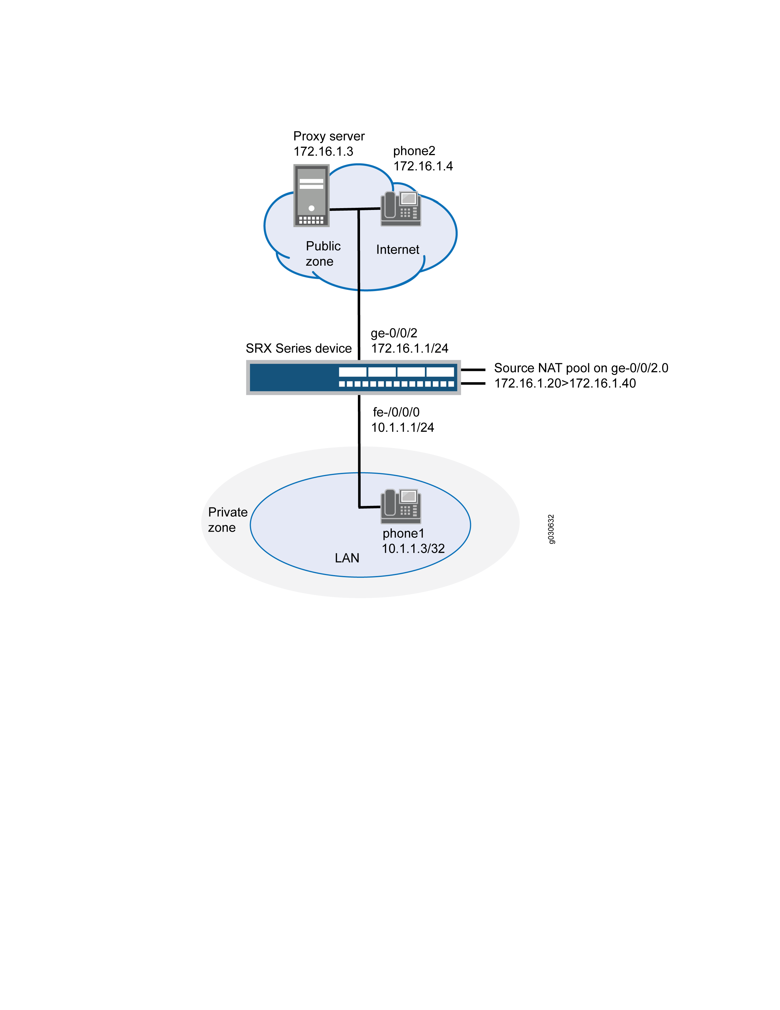
In this example, you configure source NAT as follows:
-
Define source NAT pool called sip-nat-pool to contain the IP address range from 172.16.1.20/32 through 172.16.1.40/32.
-
Create a source NAT rule set called sip-nat with a rule sip-r1 to match packets from the private zone to the public zone with the source IP address 10.1.1.3/24. For matching packets, the source address is translated to one of the IP address in sip-nat-pool.
-
Configure proxy ARP for the addresses 172.16.1.20/32 through 172.16.1.40/32 on interface ge-0/0/2.0. This allows the system to respond to ARP requests received on the interface for these addresses.
Configuration
Procedure
CLI Quick Configuration
To quickly configure this section of the example, copy the following
commands, paste them into a text file, remove any line breaks, change any
details necessary to match your network configuration, copy and paste the
commands into the CLI at the [edit] hierarchy level, and
then enter commit from configuration mode.
set interfaces ge-0/0/0 unit 0 family inet address 10.1.1.1/24 set interfaces ge-0/0/2 unit 0 family inet address 172.16.1.1/24 set security zones security-zone private address-book address phone1 10.1.1.3/32 set security zones security-zone private interfaces ge-0/0/0.0 set security zones security-zone public address-book address proxy 172.16.1.3/32 set security zones security-zone public address-book address phone2 172.16.1.4/32 set security zones security-zone public interfaces ge-0/0/2.0 set security nat source pool sip-nat-pool address 172.16.1.20/32 to 172.16.1.40/32 set security nat source address-persistent set security nat source rule-set sip-nat from zone private set security nat source rule-set sip-nat to zone public set security nat source rule-set sip-nat rule sip-r1 match source-address 10.1.1.3/24 set security nat source rule-set sip-nat rule sip-r1 then source-nat pool sip-nat-pool set security nat proxy-arp interface ge-0/0/2.0 address 172.16.1.20/32 to 172.16.1.40/32 set security policies from-zone private to-zone public policy outgoing match source-address phone1 set security policies from-zone private to-zone public policy outgoing match destination-address any set security policies from-zone private to-zone public policy outgoing match application junos-sip set security policies from-zone private to-zone public policy outgoing then permit set security policies from-zone public to-zone private policy incoming match source-address phone2 set security policies from-zone public to-zone private policy incoming match destination-address phone1 set security policies from-zone public to-zone private policy incoming match application junos-sip set security policies from-zone public to-zone private policy incoming then permit
Step-by-Step Procedure
The following example requires you to navigate various levels in the configuration hierarchy. For instructions on how to do that, see Using the CLI Editor in Configuration Mode in the CLI User Guide.
To configure a source NAT pool for incoming calls:
-
Configure interfaces.
[edit] user@host# set interfaces ge-0/0/0 unit 0 family inet address 10.1.1.1/24 user@host# set interfaces ge-0/0/2 unit 0 family inet address 172.16.1.1/24
-
Configure zones and assign interfaces to them.
[edit security zones] user@host# set security-zone private interfaces ge-0/0/0.0 user@host# set security-zone public interfaces ge-0/0/2.0
-
Configure address books.
[edit security zones] user@host# set security-zone private address-book address phone1 10.1.1.3/32 user@host# set security-zone public address-book address proxy 172.16.1.3/32 user@host# set security-zone public address-book address phone2 172.16.1.4/32
-
Configure a source NAT pool.
[edit security nat] user@host# set source pool sip-nat-pool address 172.16.1.20/32 to 172.16.1.40/32
-
Configure a source NAT rule set with a rule.
[edit security nat source rule-set sip-nat] user@host# set from zone private user@host# set to zone public user@host# set rule sip-r1 match source-address 10.1.1.3/24 user@host# set rule sip-r1 then source-nat pool sip-nat-pool
-
Enable persistent NAT.
[edit security nat] user@host# set source address-persistent
-
Configure proxy ARP.
[edit security nat] user@host# set proxy-arp interface ge-0/0/2.0 address 172.16.1.20/32 to 172.16.1.40/32
-
Configure a security policy to allow outgoing SIP traffic.
[edit security policies from-zone private to-zone public policy outgoing] set match source-address phone1 set match destination-address any set match application junos-sip set then permit
-
Configure a security policy to allow incoming SIP traffic.
[edit security policies from-zone public to-zone private policy incoming] set match source-address phone2 set match destination-address phone1 set match application junos-sip set then permit
Results
From configuration mode, confirm your configuration by entering the
show interfaces, show security zones,
show security nat, and show security
policies commands. If the output does not display the intended
configuration, repeat the configuration instructions in this example to
correct it.
[edit]
user@host# show interfaces
ge-0/0/0 {
    unit 0 {
        family inet {
            address 10.1.1.1/24;
        }
    }
    }

    ge-0/0/2 {
        unit 0 {
            family inet {
                address 172.16.1.1/24;
            }
        }
    }
[edit]
user@host# show security zones
security-zone private {
address-book {
address phone1 10.1.1.3/32;
}
interfaces {
ge-0/0/0.0;
}
}
security-zone public {
address-book {
address proxy 172.16.1.3/32;
address phone2 172.16.1.4/32;
}
interfaces {
ge-0/0/2.0;
}
}
user@host# show security nat
source {
pool sip-nat-pool {
address {
172.16.1.20/32 to 172.16.1.40/32;
}
}
address-persistent;
rule-set sip-nat {
from zone private;
to zone public;
rule sip-r1 {
match {
source-address 10.1.1.3/24;
}
then {
source-nat {
pool {
sip-nat-pool;
}
}
}
}
}
}
proxy-arp {
interface ge-0/0/2.0 {
address {
172.16.1.20/32 to 172.16.1.40/32;
}
}
}
[edit]
user@host# show security policies
from-zone private to-zone public {
policy outgoing {
match {
source-address phone1;
destination-address any;
application junos-sip;
}
then {
permit;
}
}
}
from-zone public to-zone private {
policy incoming {
match {
source-address phone2;
destination-address phone1;
application junos-sip;
}
then {
permit;
}
}
}If you are done configuring the device, enter commit from
configuration mode.
Verification
To confirm that the configuration is working properly, perform these tasks:
- Verifying Source NAT Pool Usage
- Verifying Source NAT Rule Usage
- Verifying SIP ALG Status
- Verifying the Security Polices of SIP ALG
Verifying Source NAT Pool Usage
Purpose
Verify that there is traffic using IP addresses from the source NAT pool.
Action
From operational mode, enter the show security nat source pool
all command.
user@host> show security nat source pool all
Total pools: 1
Pool name : sip-nat-pool
Pool id : 4
Routing instance : default
Host address base : 0.0.0.0
Port : [1024, 63487]
port overloading : 1
Total addresses : 21
Translation hits : 0
Address range Single Ports Twin Ports
172.16.1.20 - 172.16.1.40 0 0Meaning
The Translation hits field shows that there is no traffic
used by IP addresses from the source NAT pool.
Verifying Source NAT Rule Usage
Purpose
Verify that there is traffic matching the source NAT rule.
Action
From operational mode, enter the show security nat source rule
all command.
user@host> show security nat source rule all
source NAT rule: sip-r1 Rule-set: sip-nat
Rule-Id : 1
Rule position : 1
From zone : private
To zone : public
Match
Source addresses : 0.0.0.0 - 255.255.255.255
Destination port : 0 - 0
Action : interface
Persistent NAT type : N/A
Persistent NAT mapping type : address-port-mapping
Inactivity timeout : 0
Max session number : 0
Translation hits : 0
Successful sessions : 0
Failed sessions : 0
Number of sessions : 0Meaning
The Translation hits field shows that, there is no traffic
matching the source NAT rule.
Verifying SIP ALG Status
Purpose
Verify that SIP ALG is enabled on your system.
Action
From operational mode, enter the show security alg status
command.
user@host> show security alg status
ALG Status :
  DNS      : Enabled
  FTP      : Enabled
  H323     : Disabled
  MGCP     : Disabled
  MSRPC    : Enabled
  PPTP     : Enabled
  RSH      : Disabled
  RTSP     : Disabled
  SCCP     : Disabled
  SIP      : Enabled
  SQL      : Enabled
  SUNRPC   : Enabled
  TALK     : Enabled
  TFTP     : Enabled
  IKE-ESP  : Disabled
Meaning
The output shows the SIP ALG status as follows:
-
•Enabled—Shows the SIP ALG is enabled.
-
•Disabled—Shows the SIP ALG is disabled.
Verifying the Security Polices of SIP ALG
Purpose
Verify that the source NAT between public zone and private zone is set.
Action
From operational mode, enter the show security policies
command.
user@host> show security policies
from-zone private to-zone public {
policy outgoing {
match {
source-address phone1;
destination-address any;
application junos-sip;
}
then {
permit;
}
}
from-zone public to-zone private {
policy incoming {
match {
source-address phone2;
destination-address phone1;
application junos-sip;
}
then {
permit;
}
}Meaning
The sample output shows that the source NAT between public zone and private zone is set.
Example: Configuring Static NAT for Incoming SIP Calls
This example shows how to configure a static NAT mapping that allows callers in the private zone to register with the proxy server in the public zone.
Requirements
Before you begin, understand how NAT works with the SIP ALG. See Understanding the SIP ALG and NAT.
Overview
When a SIP proxy server is located in an external or public zone, you can configure static NAT on the public interface to enable callers in the private zone to register with the proxy server.
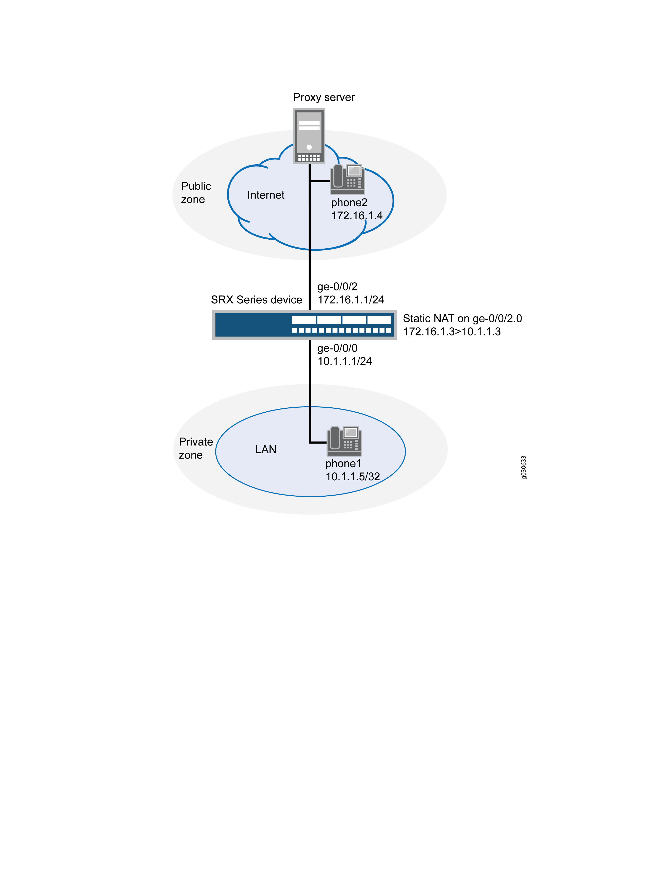
In this example (see Figure 7), phone1 is on the ge-0/0/0 interface in the private zone, and phone2 and the proxy server are on the ge-0/0/2 interface in the public zone. You create a static NAT rule set called incoming-sip with a rule called phone1 to match packets from the public zone with the destination address 172.16.1.3/32. For matching packets, the destination IP address is translated to the private address 10.1.1.3/32. You also create proxy ARP for the address 172.16.1.3/32 on interface ge-0/0/2.0. This allows the system to respond to ARP requests received on the interface for these addresses. Finally, you create a security policy called incoming that allows SIP traffic from the public zone to the private zone.
When configuring static NAT for incoming SIP calls, make sure to configure one public address for each private address in the private zone.
Configuration
Procedure
CLI Quick Configuration
To quickly configure this section of the example, copy the following
commands, paste them into a text file, remove any line breaks, change any
details necessary to match your network configuration, copy and paste the
commands into the CLI at the [edit] hierarchy level, and
then enter commit from configuration mode.
set interfaces ge-0/0/0 unit 0 family inet address 10.1.1.1/24 set interfaces ge-0/0/2 unit 0 family inet address 172.16.1.1/24 set security zones security-zone private interfaces ge-0/0/0.0 set security zones security-zone private address-book address phone1 10.1.1.5/32 set security zones security-zone public interfaces ge-0/0/2.0 set security zones security-zone public address-book address proxy 172.16.1.3/32 set security zones security-zone public address-book address phone2 172.16.1.4/32 set security nat static rule-set incoming-sip from zone public set security nat static rule-set incoming-sip rule phone1 match destination-address 172.16.1.3/32 set security nat static rule-set incoming-sip rule phone1 then static-nat prefix 10.1.1.3/32 set security nat proxy-arp interface ge-0/0/2.0 address 172.16.1.3/32 set security policies from-zone public to-zone private policy incoming match source-address phone2 set security policies from-zone public to-zone private policy incoming match source-address proxy set security policies from-zone public to-zone private policy incoming match destination-address phone1 set security policies from-zone public to-zone private policy incoming match application junos-sip set security policies from-zone public to-zone private policy incoming then permit set security policies from-zone private to-zone public policy outgoing match source-address phone1 set security policies from-zone private to-zone public policy outgoing match destination-address phone2 set security policies from-zone private to-zone public policy outgoing match destination-address proxy set security policies from-zone private to-zone public policy outgoing match application junos-sip set security policies from-zone private to-zone public policy outgoing then permit
Step-by-Step Procedure
The following example requires you to navigate various levels in the configuration hierarchy. For instructions on how to do that, see Using the CLI Editor in Configuration Mode in the CLI User Guide.
To configure static NAT for incoming calls:
-
Configure interfaces.
[edit]
user@host# set interfaces ge-0/0/0 unit 0 family inet address 10.1.1.1/24
user@host# set interfaces ge-0/0/2 unit 0 family inet address 172.16.1.1/24
-
Create security zones.
[edit security zones]
user@host# set security-zone private interfaces ge-0/0/0.0
user@host# set security-zone public interfaces ge-0/0/2.0
-
Assign addresses to the security zones.
[edit security zones] user@host# set security-zone private address-book address phone1 10.1.1.5/32 user@host# set security-zone public address-book address proxy 172.16.1.3/32 user@host# set security-zone public address-book address phone2 172.16.1.4/32
-
Create a static NAT rule set with a rule.
[edit security nat static rule-set incoming-sip] user@host# set from zone public user@host# set rule phone1 match destination-address 172.16.1.3/32 user@host# set rule phone1 then static-nat prefix 10.1.1.3/32
-
Configure proxy ARP.
[edit security nat] user@host# set proxy-arp interface ge-0/0/2.0 address 172.16.1.3/32
-
Define a security policy to allow incoming SIP traffic.
[edit security policies from-zone public to-zone private policy incoming] user@host# set match source-address phone2 user@host# set match source-address proxy user@host# set match destination-address phone1 user@host# set match application junos-sip user@host# set then permit
-
Define a security policy to allow outgoing SIP traffic.
[edit security policies from-zone private to-zone public policy outgoing] user@host# set match source-address phone1 user@host# set match destination-address phone2 user@host# set match destination-address proxy user@host# set match application junos-sip user@host# set then permit
Results
From configuration mode, confirm your configuration by entering the
show interfaces, show security zones,
show security nat, and show security
policies commands. If the output does not display the intended
configuration, repeat the configuration instructions in this example to
correct it.
[edit]
user@host# show interfaces
ge-0/0/0 {
unit 0 {
family inet {
address 10.1.1.1/24;
}
}
}
ge-0/0/2 {
unit 0 {
family inet {
address 172.16.1.1/24;
}
}
}
[edit]
user@host# show security zones
security-zone private {
address-book {
address phone1 10.1.1.5/32;
}
interfaces {
ge-0/0/0.0;
}
}
security-zone public {
address-book {
address proxy 172.16.1.3/32;
address phone2 172.16.1.4/32;
}
interfaces {
ge-0/0/2.0;
}
}[edit]
user@host# show security nat
static {
rule-set incoming-sip {
from zone public;
rule phone1 {
match {
destination-address 172.16.1.3/32;
}
then {
static-nat prefix 10.1.1.3/32;
}
}
}
}
proxy-arp {
interface ge-0/0/2.0 {
address {
172.16.1.3/32;
}
}
}[edit]
user@host# show security policies
from-zone public to-zone private {
policy incoming {
match {
source-address phone2;
destination-address phone1;
application junos-sip;
}
then {
permit;
}
}
}
from-zone private to-zone public {
policy outgoing {
match {
source-address phone1;
destination-address [phone2 proxy];
application junos-sip;
}
then {
permit;
}
}
}If you are done configuring the device, enter commit from
configuration mode.
Verification
To confirm that the configuration is working properly, perform these tasks:
- Verifying Static NAT Configuration
- Verifying SIP ALG Status
- Verifying the Security Polices of SIP ALG
Verifying Static NAT Configuration
Purpose
Verify that there is traffic matching the static NAT rule set.
Action
From operational mode, enter the show security nat static rule
all command.
user@host> show security nat static rule all
Static NAT rule: phone1 Rule-set: incoming-sip Rule-Id : 1 Rule position : 1 From zone : public Destination addresses : 172.16.1.3 Host addresses : 172.16.1.4 Netmask : 24 Host routing-instance : N/A Translation hits : 4 Successful sessions : 4 Failed sessions : 0 Number of sessions : 4
Meaning
The Translation hits field shows that there is traffic
matching the static NAT rule set.
Verifying SIP ALG Status
Purpose
Verify that SIP ALG is enabled on your system.
Action
From operational mode, enter the show security alg status
command.
user@host> show security alg status
ALG Status :
  DNS      : Enabled
  FTP      : Enabled
  H323     : Disabled
  MGCP     : Disabled
  MSRPC    : Enabled
  PPTP     : Enabled
  RSH      : Disabled
  RTSP     : Disabled
  SCCP     : Disabled
  SIP      : Enabled
  SQL      : Enabled
  SUNRPC   : Enabled
  TALK     : Enabled
  TFTP     : Enabled
  IKE-ESP  : Disabled
Meaning
The output shows the SIP ALG status as follows:
-
•Enabled—Shows the SIP ALG is enabled.
-
•Disabled—Shows the SIP ALG is disabled.
Verifying the Security Polices of SIP ALG
Purpose
Verify that the static NAT between public zone and private zone is set.
Action
From operational mode, enter the show security policies
command.
user@host> show security policies
from-zone public to-zone private {
policy incoming {
match {
source-address [ phone2 proxy ];
destination-address phone1;
application junos-sip;
}
then {
permit;
}
}
}
from-zone private to-zone public {
policy outgoing {
match {
source-address phone1;
destination-address [ phone2 proxy ];
application junos-sip;
}
then {
permit;
}
}
}Meaning
The sample output shows that the static NAT between public zone and private zone is set.
Example: Configuring the SIP Proxy in the Private Zone and NAT in the Public Zone
This example shows how to configure a SIP proxy server in a private zone and static NAT in a public zone to allow callers in the public zone to register with the proxy server.
Requirements
Before you begin, understand how NAT works with the SIP ALG. See Understanding the SIP ALG and NAT.
Overview
With the SIP proxy server in the private zone, you can configure static NAT on the external, or public, interface to allow callers in the public zone to register with the proxy server.
In this example (see Figure 8), phone1 and the SIP proxy server are on the ge-0/0/0 interface in the private zone, and phone2 is on the ge-0/0/2 interface in the public zone. You configure a static NAT rule for the proxy server to allow phone2 to register with the proxy server, and then create a policy called outgoing that allows SIP traffic from the public to the private zone to enable callers in the public zone to register with the proxy server. You also configure a policy called incoming from the private to the public zone to allow phone1 to call out.
Topology
Figure 8 shows configuring SIP proxy in the private zone and NAT in a public zone.
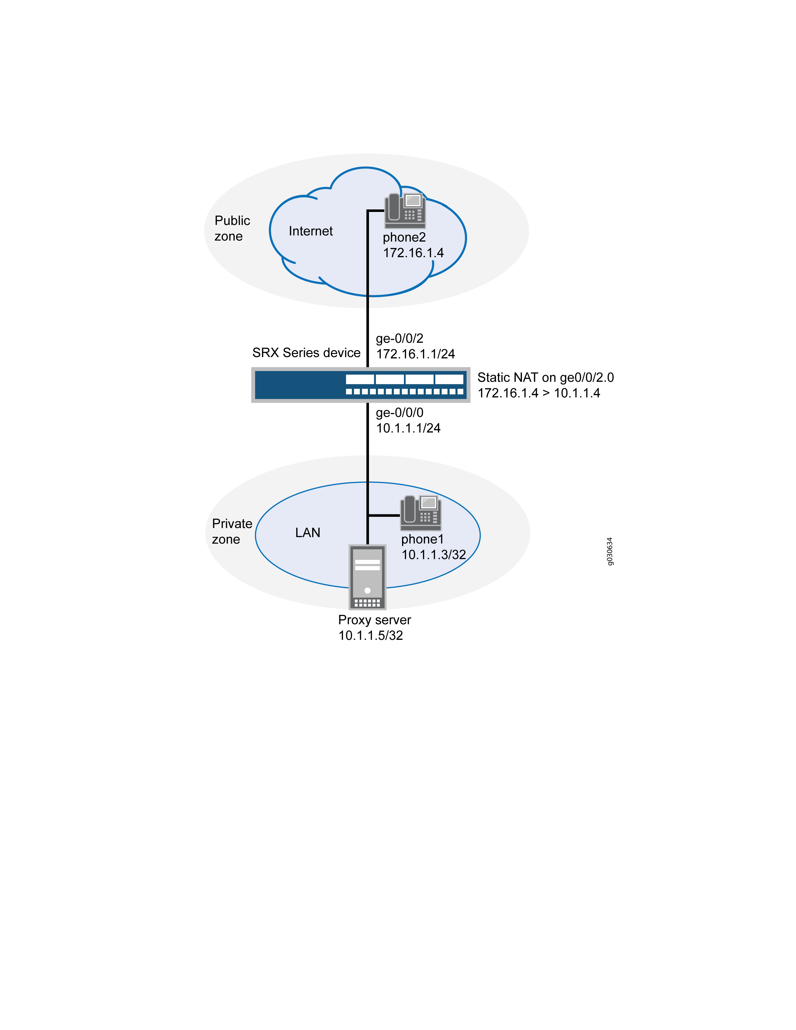
In this example, you configure NAT as follows:
-
Configure static NAT on the ge-0/0/2 interface to the proxy server with a rule set called incoming-sip with a rule called proxy to match packets from the public zone with the destination address 172.16.1.2/32. For matching packets, the destination IP address is translated to the private address 10.1.1.5/32.
-
Configure a second rule set called sip-phones with a rule called phone1 to enable interface NAT for communication from phone1 to phone2.
Configuration
Procedure
CLI Quick Configuration
To quickly configure this section of the example, copy the following
commands, paste them into a text file, remove any line breaks, change any
details necessary to match your network configuration, copy and paste the
commands into the CLI at the [edit] hierarchy level, and
then enter commit from configuration mode.
set interfaces ge-0/0/0 unit 0 family inet address 10.1.1.1/24 set interfaces ge-0/0/2 unit 0 family inet address 172.16.1.1/24 set interfaces ge-0/0/2 unit 0 proxy-arp set security zones security-zone private address-book address phone1 10.1.1.3/32 set security zones security-zone private address-book address proxy 10.1.1.5/32 set security zones security-zone private interfaces ge-0/0/0.0 set security zones security-zone public address-book address phone2 172.16.1.4/32 set security zones security-zone public interfaces ge-0/0/2.0 set security nat source rule-set sip-phones from zone private set security nat source rule-set sip-phones to zone public set security nat source rule-set sip-phones rule phone1 match source-address 10.1.1.3/32 set security nat source rule-set sip-phones rule phone1 then source-nat interface set security nat static rule-set incoming-sip from zone public set security nat static rule-set incoming-sip rule proxy match destination-address 172.16.1.2/32 set security nat static rule-set incoming-sip rule proxy then static-nat prefix 10.1.1.5/32 set security nat proxy-arp interface ge-0/0/2.0 address 172.16.1.2/32 set security policies from-zone private to-zone public policy outgoing match source-address any set security policies from-zone private to-zone public policy outgoing match destination-address phone2 set security policies from-zone private to-zone public policy outgoing match application junos-sip set security policies from-zone private to-zone public policy outgoing then permit set security policies from-zone public to-zone private policy incoming match source-address phone2 set security policies from-zone public to-zone private policy incoming match destination-address proxy set security policies from-zone public to-zone private policy incoming match application junos-sip set security policies from-zone public to-zone private policy incoming then permit
Step-by-Step Procedure
The following example requires you to navigate various levels in the configuration hierarchy. For instructions on how to do that, see Using the CLI Editor in Configuration Mode in the CLI User Guide.
To configure static NAT for incoming calls:
-
Configure interfaces.
[edit] user@host# set interfaces ge-0/0/0 unit 0 family inet address 10.1.1.1/24 user@host# set interfaces ge-0/0/2 unit 0 family inet address 172.16.1.1/24 user@host# set interfaces ge-0/0/2 unit 0 proxy-arp
-
Configure security zones.
[edit security zones]
user@host# set security-zone private interfaces ge-0/0/0.0
user@host# set security-zone public interfaces ge-0/0/2.0
-
Assign addresses to the security zones.
[edit security zones] user@host# set security-zone private address-book address phone1 10.1.1.3/32 user@host# set security-zone private address-book address proxy 10.1.1.5/32 user@host# set security-zone public address-book address phone2 172.16.1.4/32
-
Create a rule set for static NAT and assign a rule to it.
[edit security nat static rule-set incoming-sip] user@host# set from zone public user@host# set rule proxy match destination-address 172.16.1.2/32 user@host# set rule proxy then static-nat prefix 10.1.1.5/32
-
Configure proxy-arp for the 172.16.1.2/32 address.
[edit security nat] user@host# proxy-arp interface ge-0/0/2.0 address 172.16.1.2/32
-
Configure the second rule set and assign a rule to it.
[edit security nat source rule-set sip-phones] user@host# set from zone private user@host# set to zone public user@host# set rule phone1 match source-address 10.1.1.3/32 user@host# set rule phone1 then source-nat interface
-
Configure a security policy for outgoing traffic.
[edit security policies from-zone private to-zone public policy outgoing] user@host# set match source-address any user@host# set match destination-address phone2 user@host# set match application junos-sip user@host# set then permit
-
Configure a security policy for incoming traffic.
[edit security policies from-zone public to-zone private policy incoming] user@host# set match source-address phone2 user@host# set match destination-address proxy user@host# set match application junos-sip user@host# set then permit
Results
From configuration mode, confirm your configuration by entering the
show interfaces, show security zones,
show security nat, and show security
policies commands. If the output does not display the intended
configuration, repeat the configuration instructions in this example to
correct it.
[edit]
user@host# show interfaces
ge-0/0/0 {
unit 0 {
family inet {
address 10.1.1.1/24;
}
}
}
ge-0/0/2 {
unit 0 {
proxy-arp;
family inet {
address 172.16.1.1/24;
}
}
}
[edit]
user@host# show security zones
security-zone private {
address-book {
address phone1 10.1.1.3/32;
address proxy 10.1.1.5/32;
}
interfaces {
ge-0/0/0.0;
}
}
security-zone public {
address-book {
address phone2 172.16.1.4/32;
}
interfaces {
ge-0/0/2.0;
}
}
[edit]
user@host# show security nat
source {
rule-set sip-phones {
from zone private;
to zone public;
rule phone1 {
match {
source-address 10.1.1.3/32;
}
then {
source-nat {
interface;
}
}
}
}
}
static {
rule-set incoming-sip {
from zone public;
rule proxy {
match {
destination-address 172.16.1.2/32;
}
then {
static-nat prefix 10.1.1.5/32;
}
}
}
proxy-arp {
interface ge-0/0/2.0 {
address {
172.16.1.2/32;
}
}
}
}
[edit]
user@host# show security policies
from-zone private to-zone public {
policy outgoing {
match {
source-address any;
destination-address phone2;
application junos-sip;
}
then {
permit;
}
}
}
from-zone public to-zone private {
policy incoming {
match {
source-address phone2;
destination-address proxy;
application junos-sip;
}
then {
permit;
}
}
}If you are done configuring the device, enter commit from
configuration mode.
Verification
To confirm that the configuration is working properly, perform these tasks:
- Verifying Static NAT Configuration
- Verifying SIP ALG Status
- Verifying Source NAT Rule
- Verifying Security Flow Session
Verifying Static NAT Configuration
Purpose
Verify that there is traffic matching the static NAT rule set.
Action
From operational mode, enter the show security nat static rule all
command. View the Translation hits field to check for traffic that
matches the rule.
user@host> show security nat static rule all
Total static-nat rules: 1
Total referenced IPv4/IPv6 ip-prefixes: 2/0
Static NAT rule: proxy Rule-set: incoming-sip
Rule-Id : 2
Rule position : 1
From zone : public
Destination addresses : 172.16.1.2
Host addresses : 10.1.1.5
Netmask : 32
Host routing-instance : N/A
Translation hits : 23
Successful sessions : 23
Failed sessions : 0
Number of sessions : 0Meaning
The Translation hits field shows that, there are 23 traffic
matching the static NAT rule.
Verifying SIP ALG Status
Purpose
Verify that SIP ALG is enabled on your system.
Action
From operational mode, enter the show security alg status
command.
user@host> show security alg status ALG Status : DNS : Enabled FTP : Enabled H323 : Disabled MGCP : Disabled MSRPC : Enabled PPTP : Enabled RSH : Disabled RTSP : Disabled SCCP : Disabled SIP : Enabled SQL : Enabled SUNRPC : Enabled TALK : Enabled TFTP : Enabled IKE-ESP : Disabled
Meaning
The output shows the SIP ALG status as follows:
-
Enabled—Shows the SIP ALG is enabled.
-
Disabled—Shows the SIP ALG is disabled.
Verifying Source NAT Rule
Purpose
Verify that the source NAT rule configuration.
Action
From operational mode, enter the show security nat source rule
all command.
user@host> show security nat source rule all
Total referenced IPv4/IPv6 ip-prefixes: 1/0
source NAT rule: phone1 Rule-set: sip-phones
Rule-Id : 1
Rule position : 1
From zone : private
To zone : public
Match
Source addresses : 10.1.1.3 - 10.1.1.3
Action : interface
Persistent NAT type : N/A
Persistent NAT mapping type : address-port-mapping
Inactivity timeout : 0
Max session number : 0
Translation hits : 88
Successful sessions : 88
Failed sessions : 0
Number of sessions : 0Meaning
The Translation hits field shows that, there are 88 traffic
matching the source NAT rule.
Verifying Security Flow Session
Purpose
Verify that the NAT translation phone1 to phone2.
Action
From operational mode, enter the run show security flow
session command.
user@host> run show security flow session Session ID: 169, Policy name: allow-all/4, Timeout: 2, Valid In: 10.1.1.3/4 --> 172.16.1.4/52517;icmp, Conn Tag: 0x0, If: ge-0/0/0.0, Pkts: 1, Bytes: 84, Out: 172.16.1.4/52517 --> 172.16.1.1/25821;icmp, Conn Tag: 0x0, If: ge-0/0/1.0, Pkts: 1, Bytes: 84,
Meaning
The output displays the NAT translation phone1 to phone2.
Example: Configuring a Three-Zone SIP ALG and NAT Scenario
This example shows how to configure a SIP proxy server in a private zone and static NAT in a public zone to allow callers in the public zone to register with the proxy server.
Requirements
Before you begin, understand how NAT works with the SIP ALG. See Understanding the SIP ALG and NAT.
Overview
In a three-zone SIP configuration, the SIP proxy server is typically in a different zone from the calling and called systems. Such a scenario requires additional address and zone configuration, and policies to ensure that all systems have access to each other and to the proxy server.
In this example, phone1 is on the ge-0/0/0.0 interface in the private zone, phone2 is on the ge-0/0/2.0 interface in the public zone, and the proxy server is on the ge-0/0/1.0 interface in the DMZ. You configure static NAT rule for phone1 in the private zone. You then create policies for traffic traversing from the private zone to the DMZ and from the DMZ to the private zone, from the public zone to the DMZ and from the DMZ to the public zone, and from the private zone to the public zone. The arrows in Figure 9 show the flow of SIP signaling traffic when phone2 in the public zone places a call to phone1 in the private zone. After the session is initiated, the data flows directly between phone1 and phone2.
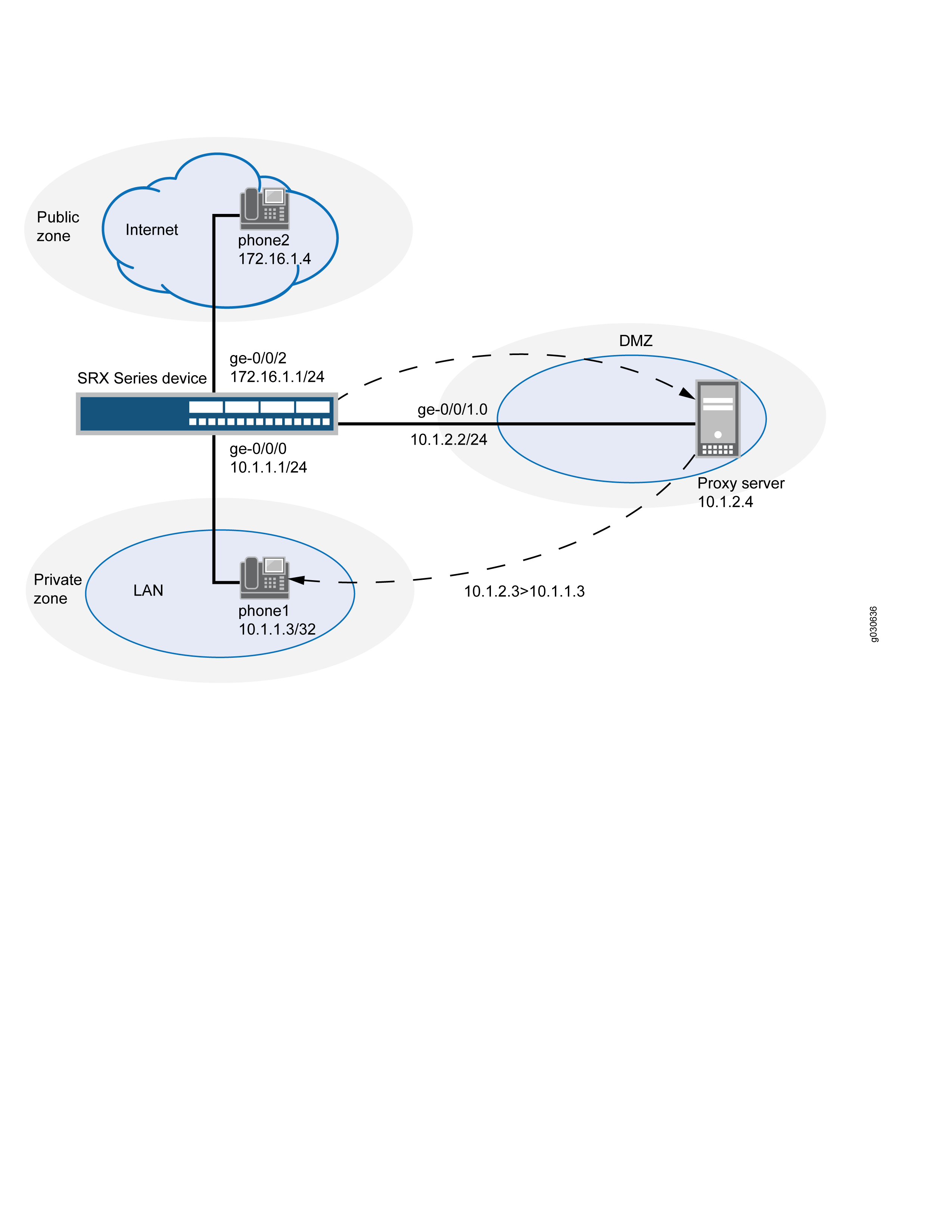
In this example, you configure NAT as follows:
-
Configure a static NAT rule set called incoming-sip with a rule phone1 to match packets from the public zone with the destination address 10.1.2.3/32. For matching packets, the destination IP address is translated to the private address 10.1.1.3/32.
-
Configure proxy ARP for the address 10.1.2.3/32 on interface ge-0/0/1.0 allowing the system to respond to ARP requests received on the interface for this address.
-
Configure a second rule set called sip-phones with a rule r1 to enable interface NAT for communication from phone1 to the proxy server and from phone1 to phone2.
Configuration
Procedure
CLI Quick Configuration
To quickly configure this section of the example,
copy the following commands, paste them into a text file, remove any
line breaks, change any details necessary to match your network configuration,
copy and paste the commands into the CLI at the [edit] hierarchy
level, and then enter commit from configuration mode.
set security nat static rule-set sip-phone from zone private set security nat static rule-set sip-phone from zone public set security nat static rule-set sip-phone rule phone1 match destination-address 10.1.2.3/32 set security nat static rule-set sip-phone rule phone1 then static-nat prefix 10.1.1.3/32 set interfaces ge-0/0/0 unit 0 family inet address 10.1.1.1/24 set interfaces ge-0/0/1 unit 0 family inet address 10.1.2.2/24 set interfaces ge-0/0/2 unit 0 family inet address 172.16.1.1/24 set security zones security-zone private address-book address phone1 10.1.1.3/32 set security zones security-zone private interfaces ge-0/0/0.0 set security zones security-zone public address-book address phone2 172.16.1.4/32 set security zones security-zone public interfaces ge-0/0/2.0 set security zones security-zone dmz address-book address proxy 10.1.2.4/32 set security zones security-zone dmz interfaces ge-0/0/1.0 set security nat source rule-set sip-phones from zone private set security nat source rule-set sip-phones to zone dmz set security nat source rule-set sip-phones rule r1 match source-address 10.1.1.3/32 set security nat source rule-set sip-phones rule r1 then source-nat interface set security policies from-zone private to-zone dmz policy private-to-proxy match source-address phone1 set security policies from-zone private to-zone dmz policy private-to-proxy match destination-address proxy set security policies from-zone private to-zone dmz policy private-to-proxy match application junos-sip set security policies from-zone private to-zone dmz policy private-to-proxy then permit set security policies from-zone public to-zone dmz policy public-to-proxy match source-address phone2 set security policies from-zone public to-zone dmz policy public-to-proxy match destination-address proxy set security policies from-zone public to-zone dmz policy public-to-proxy match application junos-sip set security policies from-zone public to-zone dmz policy public-to-proxy then permit set security policies from-zone public to-zone private policy public-to-private match source-address phone2 set security policies from-zone public to-zone private policy public-to-private match destination-address phone1 set security policies from-zone public to-zone private policy public-to-private match application junos-sip set security policies from-zone public to-zone private policy public-to-private then permit set security policies from-zone private to-zone public policy private-to-public match source-address phone1 set security policies from-zone private to-zone public policy private-to-public match destination-address phone2 set security policies from-zone private to-zone public policy private-to-public match application junos-sip set security policies from-zone private to-zone public policy private-to-public then permit set security policies from-zone dmz to-zone private policy proxy-to-private match source-address proxy set security policies from-zone dmz to-zone private policy proxy-to-private match destination-address phone1 set security policies from-zone dmz to-zone private policy proxy-to-private match application junos-sip set security policies from-zone dmz to-zone private policy proxy-to-private then permit set security policies from-zone dmz to-zone public policy proxy-to-public match source-address proxy set security policies from-zone dmz to-zone public policy proxy-to-public match destination-address phone2 set security policies from-zone dmz to-zone public policy proxy-to-public match application junos-sip set security policies from-zone dmz to-zone public policy proxy-to-public then permit
Step-by-Step Procedure
The following example requires you to navigate various levels in the configuration hierarchy. For instructions on how to do that, see Using the CLI Editor in Configuration Mode in the CLI User Guide.
To configure a SIP proxy server in a private zone and static NAT in a public zone:
-
Create a rule set for static NAT and assign a rule to it.
[edit security nat static rule-set] user@host# sip-phone from zone private user@host# sip-phone from zone public user@host# sip-phone rule phone1 match destination-address 10.1.2.3/32 user@host# phone1 then static-nat prefix 10.1.1.3/32
-
Configure interfaces.
[edit] user@host# set interfaces ge-0/0/0 unit 0 family inet address 10.1.1.1/24 user@host# set interfaces ge-0/0/1 unit 0 family inet address 10.1.2.2/24 user@host# set interfaces ge-0/0/2 unit 0 family inet address 172.16.1.1/24
-
Configure security zones.
[edit security zones] user@host# set security-zone private interfaces ge-0/0/0.0 user@host# set security-zone public interfaces ge-0/0/2.0 user@host# set security-zone dmz interfaces ge-0/0/1.0
-
Assign addresses to the security zones.
[edit security zones] user@host# set security-zone private address-book address phone1 10.1.1.3/32 user@host# set security-zone public address-book address phone2 172.16.1.4/32 user@host# set security-zone dmz address-book address proxy 10.1.2.4/32
-
Configure interface NAT for communication from phone1 to proxy.
[edit security nat source rule-set sip-phones] user@host# set from zone private user@host# set to zone dmz user@host# set rule r1 match source-address 10.1.1.3/32 user@host# set rule r1 then source-nat interface
-
Configure a security policy to allow traffic from zone private to zone DMZ.
[edit security policies from-zone private to-zone dmz policy private-to-proxy] user@host# set match source-address phone1 user@host# set match destination-address proxy user@host# set match application junos-sip user@host# set then permit
-
Configure a security policy to allow traffic from zone public to zone DMZ.
[edit security policies from-zone public to-zone dmz policy public-to-proxy] user@host# set match source-address phone2 user@host# set match destination-address proxy user@host# set match application junos-sip user@host# set then permit
-
Configure a security policy to allow traffic from zone private to zone public.
[edit security policies from-zone private to-zone public policy private-to-public] user@host# set match source-address phone1 user@host# set match destination-address phone2 user@host# set match application junos-sip user@host# set then permit
-
Configure a security policy to allow traffic from zone public to zone private.
[edit security policies from-zone public to-zone private policy public-to-private] user@host# set match source-address phone2 user@host# set match destination-address phone1 user@host# set match application junos-sip user@host# set then permit
-
Configure a security policy to allow traffic from zone DMZ to zone private.
[edit security policies from-zone dmz to-zone private policy proxy-to-private] user@host# set match source-address proxy user@host# set match destination-address phone1 user@host# set match application junos-sip user@host# set then permit
-
Configure a security policy to allow traffic from zone DMZ to zone public.
[edit security policies from-zone dmz to-zone public policy proxy-to-public] user@host# set match source-address proxy user@host# set match destination-address phone2 user@host# set match application junos-sip user@host# set then permit
Results
From configuration mode, confirm your configuration
by entering the show interfaces, show security zones, show security nat, and show security policies commands. If the output does not display the intended configuration,
repeat the configuration instructions in this example to correct it.
[edit]
user@host# show interfaces
ge-0/0/0 {
unit 0 {
family inet {
address 10.1.1.1/24;
}
}
}
ge-0/0/1 {
unit 0 {
family inet {
address 10.1.2.2/24;
}
}
}
ge-0/0/2 {
unit 0 {
family inet {
address 172.16.1.1/24;
}
}
}[edit]
user@host# show security zones
security-zone private {
address-book {
address phone1 10.1.1.3/32;
}
interfaces {
ge-0/0/0.0;
}
}
security-zone public {
address-book {
address phone2 172.16.1.4/32;
}
interfaces {
ge-0/0/2.0;
}
}
security-zone dmz {
address-book {
address proxy 10.1.2.4/32;
}
interfaces {
ge-0/0/1.0;
}
}[edit]
user@host# show security nat
static {
rule-set sip-phone {
from zone [ private public ];
rule phone1 {
match {
destination-address 10.1.2.3/32;
}
then {
static-nat {
prefix {
10.1.1.3/32;
}
}
}
}
}
}
source {
rule-set sip-phones {
from zone private;
to zone dmz;
rule r1 {
match {
source-address 10.1.1.3/32;
}
then {
source-nat {
interface;
}
}
}
}
}
proxy-arp {
interface ge-0/0/1.0 {
address {
10.1.2.3/32;
}
}
}[edit]
user@host# show security policies
from-zone private to-zone dmz {
policy private-to-proxy {
match {
source-address phone1;
destination-address proxy;
application junos-sip;
}
then {
permit;
}
}
}
from-zone public to-zone dmz {
policy public-to-proxy {
match {
source-address phone2;
destination-address proxy;
application junos-sip;
}
then {
permit;
}
}
}
from-zone public to-zone private {
policy public-to-private {
match {
source-address phone2;
destination-address phone1;
}
then {
permit;
}
}
}
from-zone private to-zone public {
policy private to-zone public {
match {
source-address phone1;
destination-address phone2;
}
then {
permit;
}
}
}
from-zone dmz to-zone private {
policy proxy-to-private {
match {
source-address proxy;
destination-address phone2;
application junos-sip;
}
then {
permit;
}
}
}If you are done configuring the device, enter commit from configuration mode.
Verification
To confirm that the configuration is working properly, perform these tasks:
Verifying Source NAT Rule Usage
Purpose
Verify that there is traffic matching the source NAT rule.
Action
From operational mode, enter the show security
nat source rule all command. View the Translation hits field
to check for traffic that matches the rule.
user@host> show security nat source rule all
source NAT rule: r1 Rule-set: sip-phones
Rule-Id : 1
Rule position : 1
From zone : private
To zone : public
Match
Source addresses : 0.0.0.0 - 255.255.255.255
Destination port : 0 - 0
Action : interface
Persistent NAT type : N/A
Persistent NAT mapping type : address-port-mapping
Inactivity timeout : 0
Max session number : 0
Translation hits : 0
Successful sessions : 0
Failed sessions : 0
Number of sessions : 0Meaning
The Translation hits field shows that, there
is no traffic matching the source NAT rule.
Verifying Static NAT Rule Usage
Purpose
Verify that there is traffic matching the static NAT rule.
Action
From operational mode, enter the show security
nat static rule all command. View the Translation hits field
to check for traffic that matches the rule.
user@host> show security nat static rule all
Total static-nat rules: 1
Total referenced IPv4/IPv6 ip-prefixes: 2/0
Static NAT rule: phone1 Rule-set: sip-phone
Rule-Id : 1
Rule position : 1
From zone : private
: public
Destination addresses : 10.1.2.3
Host addresses : 10.1.2.4
Netmask : 32
Host routing-instance : N/A
Translation hits : 127
Successful sessions : 127
Failed sessions : 0
Number of sessions : 0Meaning
The Translation hits field shows that, the
traffic matching the static NAT rule.
Verifying SIP ALG Status
Purpose
Verify that SIP ALG is enabled on your system.
Action
From operational mode, enter the show security
alg status command.
user@host> show security alg status
ALG Status :
  DNS      : Enabled
  FTP      : Enabled
  H323     : Disabled
  MGCP     : Disabled
  MSRPC    : Enabled
  PPTP     : Enabled
  RSH      : Disabled
  RTSP     : Disabled
  SCCP     : Disabled
  SIP      : Enabled
  SQL      : Enabled
  SUNRPC   : Enabled
  TALK     : Enabled
  TFTP     : Enabled
  IKE-ESP  : Disabled
Meaning
The output shows the SIP ALG status as follows:
-
Enabled—Shows the SIP ALG is enabled.
-
Disabled—Shows the SIP ALG is disabled.
Change History Table
Feature support is determined by the platform and release you are using. Use Feature Explorer to determine if a feature is supported on your platform.