RTSP ALG
The Real-Time Streaming Protocol (RTSP) controls the delivery of data with real-time properties such as audio and video. Media can be transmitted on the same RTSP control stream. This is an HTTP-like text-based protocol, but client and server maintain session information. A session is established using the SETUP message and terminated using the TEARDOWN message. The transport (the media protocol, address, and port numbers) is negotiated in the setup and the setup-response.
Support for stateful firewall and NAT services requires that you configure the RTSP ALG for TCP port 554. The ALG monitors the control connection, opens flows dynamically for media (RTP/RTSP) streams, and performs NAT address and port rewrites.
Understanding the RTSP ALG
Overview
RTSP (Real-Time Streaming Protocol) is an Application Layer protocol for controlling the delivery of data with real-time properties. It is similar in syntax and operation to HTTP/1.1. Unlike SIP and H.323, the purpose of RTSP is to access existing media files over the network and to control the replay of the media. The typical communication is between a client (running RealPlayer for example) and a streaming media server. Commands include the ability to pause and play media files from the remote server.
RTSP is a control channel protocol between the media client and media server. The data channel uses a different protocol, usually Real-Time Transport Protocol (RTP) or RTP Control Protocol (RTCP).
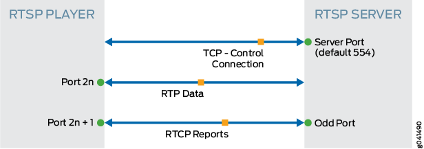
In RTSP standard mode, the client sets up three network channels with the RTSP server when media data is delivered using RTP over UDP.
RTSP runs over TCP. RTP and RTCP run over UDP. The ports for RTP and RTCP packets are dynamically negotiated by the client and server using RTSP. Because RTP and RTCP ports are dynamic, these ports cannot be allowed by a static policy. The main purpose of introducing an RTSP ALG to a firewall is to create dynamic policy (pinhole) according to the result of client/server negotiation so that RTP and RTCP traffic can pass through.
When the client and server reside in different realms, they might not be able to determine how to route to the address of the RTP or RTCP offer given by the peer. In this case, ALG needs to be involved to do translation for the RTP or RTCP offer address and modify it in the payload.
After the connection is established, the RTSP ALG monitors the messages exchanged between the client and server, tracks the status change of the dialog, and returns all the resources it acquired to support an RTSP dialog back to the system after the dialog has completed or failed.
RTSP Modes
Standard Mode
In RTSP standard mode, the client sets up three network channels with the RTSP server when media data is delivered using RTP over UDP.
A full-duplex TCP connection is used for control and negotiation. A full-duplex UDP channel is used for media data delivery using the RTP packet format. In most cases, RTP is initiated from the server. A full-duplex UDP channel called RTCP is used to provide synchronization information to the client and packet loss information to the server.
Figure 1 shows the RTSP ALG standard mode.
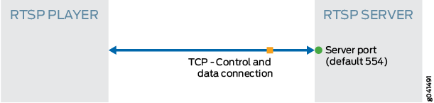
Interleave Mode
In RTSP interleave mode, media data can be made into packets using RTP or RDT over TCP. In this scenario , a single full-duplex TCP connection is used for both control and for media data delivery from the RTSP server to the client. The data stream is interleaved with the RTSP control stream.
Figure 2 shows the RTSP ALG interleave mode.
Understanding RTSP ALG Messages
RTSP Message Format
RTSP is text based and uses the ISO 10646 character set in UTF-8 encoding. Lines are terminated by CRLF, and an empty line is the separator of the message and body.
The first line is called the start-line. For request messages from client to server, the start-line represents the RTSP method. For the response message from server to client, the start-line represents the RTSP status code as the reply of method. The status code element is a 3-digit integer result code.
RTSP Methods
There are nine types of methods during one transaction.
OPTION—Represents a request for information about the communication options available on the request/response chain identified by the Request-URL. This method allows the client to determine the options, requirements, or both associated with a resource, or the capabilities of a server, without implying a resource action or initiating a resource retrieval.
DESCRIBE—Retrieves the description of a presentation or media object identified by the request URL from a server. This method might use the Accept header to specify the description formats that the client interprets.
ANNOUNCE—Request sent from client to server, this method posts the description of a presentation or media object identified by the request URL to a server. When request sent from server to client, this method updates the session description in real-time.
SETUP—Requests a URI and specifies the transport mechanism to be used for the streamed media.
PLAY—Informs the server to start sending data using the mechanism specified in SETUP.
PAUSE—Requests the stream delivery to be interrupted temporarily.
TEARDOWN—Stops the stream delivery for the given URI, freeing the resource associated with it.
GET_PARAMETER—Retrieves the value of a parameter of a presentation or stream specified in the URI.
SET_PARAMETER—Sets the value of a parameter for a presentation or stream specified by the URI.
RTSP Status Code
The first digit of the status code defines the class of response.
1**: Informational—Request received, continuing process.
2**: Success
3**: Redirection—Further action must be taken in order to complete the request.
4**: Client Error—The request contains bad syntax or cannot be fulfilled.
5**: Server Error—The server failed to fulfill an apparently valid request.
RTSP Header
The RTSP header consists of the following fields:
CSeq—Specifies the sequence number for an RTSP request-response pair. For every RTSP request containing the given sequence number, there will be a corresponding response having the same number.
Content-Length—Contains the length of the content of the method, that is, after the double CRLF following the last header.
TRANSPORT—Indicates which transport protocol is to be used and configures its parameters.
SESSION—Identifies an RTSP session started by the media server in a SETUP response and concluded by TEARDOWN on the presentation URL.
Understanding RTSP ALG Conversation and NAT
This topic provides details on typical RTSP ALG conversation.
In general, RTP and RTCP packets are bidirectional, which means that either the client or server could initiate an RTP or an RTCP session.
Figure 3 describes an example of a sample packet capture in a standard RTSP conversation.
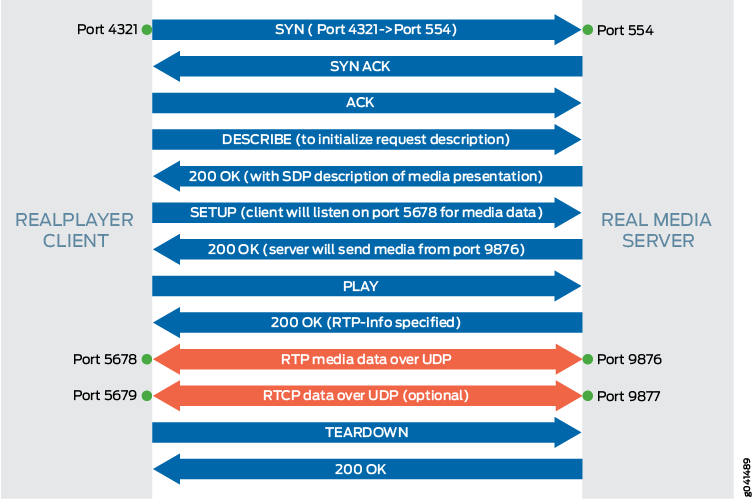
The RTSP ALG performs the following actions for a RTSP sample packet capture in a standard RTSP conversation:
-
Monitors SETUP and 200 OK messages.
-
Receives negotiated ports (6543 and 8765 in this example)
-
Opens a pinhole for UDP media data from server to client.
-
Receives the IP address in payload and translates the address if NAT is required.
Table 1 describes the RTSP payload IP NAT.
Table 1: RTSP Payload IP NAT Forward(C->S)
Reverse(S->C)
Pinhole
Payload IP Translate
Payload Port Translate
No NAT
A/4321->B/554
A/4321<-B/554
B/9876->A/5678
A/5678->B/9876
N/A
N/A
Source NAT (IPvx)
A/4321->B/554
A’/P’<-B/554
B/9876->A’/P’’
A/5678->B/9876
N/A (*)
5678<->P’’
Destination NAT (IPvx)
A/4321->B’/554
A/4321<-B/554
B/9876->A/5678
A/5678->B’/9876
B’ -> B (**)
N/A
NAT64
A/4321->B’’/554
A’’/Q’<-B/554
B/9876->A’’/Q’’
A/5678->B’’/9876
B’’(IPv6)->B(IPv4)
5678<->Q’’
NAT46
A/4321->B’’’/554
A’’’/R’<-B/554
B/9876->A’’’/R’’
A/5678->B’’’/9876
B’’’(IPv4)->B(IPv6)
5678<->R’’
In Table 1, the following letters and symbols are used:
-
A—RTSP client IP address
-
A’—Translated IPv4 or IPv6 address of RTSP client
-
A’’—Translated IPv4 address
-
A’’’—Translated IPv6 address
-
B—RTSP server IP address
-
B’—RTSP server IP address before destination NAT
-
B’’—RTSP server IP address at IPv6 realm
-
B’’’— RTSP server IP address at IPv4 realm
-
P’—Translated Port(translates from 4321) of RTSP client
-
P’’—Translated Port(translates from 5678 in message payload) of RTSP client
-
Q’—Translated (IPv6 to IPv4) Port(translates from 4321) of RTSP client
-
Q’’—Translated (IPv6 to IPv4) Port (translates from 5678 in message payload) of RTSP client
-
R’—Translated (IPv4 to IPv6) Port (translates from 4321) of RTSP client
-
R’’—Translated (IPv4 to IPv6) Port (translates from 5678 in message payload) of RTSP client
-
(*)—RTSP server IP address B appears in payload message; it does not need to translate
-
(**)—IP address B’ appears in payload message from client to server; it needs to translate to B
-
Example: Configuring the RTSP ALG
This example shows how to configure the RTSP ALG to pass through RTSP traffic with a source NAT pool on Juniper Networks devices.
Requirements
Configure proxy ARP for all IP addresses in the source NAT pool.
Enable the RTSP ALG.
Understand the basics concepts of the RTSP ALG. See Understanding the RTSP ALG.
Overview
In this example, the RTSP ALG is configured to monitor and allow RTSP traffic transferring media between client and server located on opposite sides of a Juniper Networks device.
Configuration
- Enabling RTSP ALG
- Configuring a NAT Source Pool and Rule Set and a Policy
- Configuring RTSP ALG trace options
Enabling RTSP ALG
CLI Quick Configuration
To quickly configure this section of the example,
copy the following commands, paste them into a text file, remove any
line breaks, change any details necessary to match your network configuration,
copy and paste the commands into the CLI at the [edit] hierarchy
level, and then enter commit from configuration mode.
To configure proxy ARP for all IP addresses in the source NAT pool and to enable RTSP ALG:
set security nat proxy-arp interface <interface-name> address 10.10.10.1/32 to 10.10.10.10/32
set security alg rtsp
Enter commit from configuration mode.
Configuring a NAT Source Pool and Rule Set and a Policy
CLI Quick Configuration
To quickly configure this section of the example,
copy the following commands, paste them into a text file, remove any
line breaks, change any details necessary to match your network configuration,
copy and paste the commands into the CLI at the [edit] hierarchy
level, and then enter commit from configuration mode.
set security nat source pool pool1 address 10.10.10.1/32 to 10.10.10.10/32
set security zones security-zone green address-book address sa1 1.1.1.0/24
set security zones security-zone red address-book address da1 2.2.2.0/24
set security nat source rule-set rs1 from zone green
set security nat source rule-set rs1 to zone red
set security nat source rule-set rs1 rule r1 match source-address 1.1.1.0/24
set security nat source rule-set rs1 rule r1 match destination-address 2.2.2.0/24
set security nat source rule-set rs1 rule r1 then source-nat pool pool1
set security policy from-zone green to-zone red policy pol1 match destination-address da1
set security policy from-zone green to-zone red policy pol1 match source-address sa1
set security policy from-zone green to-zone red policy pol1 match application junos-rtsp
set security policy from-zone green to-zone red policy pol1 then permit
Enter commit from configuration mode.
If you are not sure of the RTSP client and server IP address, you can replace “da1” and “sa1” with “any”.
Step-by-Step Procedure
The following example requires you to navigate various levels in the configuration hierarchy. For instructions on how to do that, see Using the CLI Editor in Configuration Mode in the CLI User Guide.
To configure a source NAT pool:
Create a NAT source pool.
[edit security]
user@host# set nat source pool pool1 address 10.10.10.1/32 to 10.10.10.10/32
Configure security zone address book entries.
[edit security zones security-zone]
user@host# set green address-book address sa1 1.1.1.0/24
user@host# set red address-book address da1 2.2.2.0/24
Create a NAT source rule set.
[edit security nat source rule-set rs1]
user@host# set from zone green
user@host# set to zone red
user@host# set rule r1 match source-address 1.1.1.0/24
user@host# set rule r1 match destination-address 2.2.2.0/24
user@host# set rule r1 then source-nat pool pool1
Configure a policy.
[edit security policies from-zone green to-zone red policy pol1]
user@host# set match source-address sa1
user@host# set match destination-address da1
user@host# set match application junos-rtsp
user@host# set then permit
Results
From configuration mode, confirm your configuration
by entering the show security nat and show security
policies commands. If the output does not display the intended
configuration, repeat the configuration instructions in this example
to correct it.
[edit ]
user@host# show security nat
source {
    pool pool1 {
        address {
            10.10.10.1/32 to 10.10.10.10/32;
        }
    }
    rule-set rs1 {
        from zone green;
        to zone red;
        rule r1 {
            match {
                source-address 1.1.1.0/24;
                destination-address 2.2.2.0/24;
            }
            then {
                source-nat {
                    pool {
                        pool1;
                    }
                }
            }
        }
    }
[edit]
user@host# show security policies
from-zone green to-zone red {policy pol1 {
    policy pol1 {
        match {
            source-address sa1;
            destination-address da1;
            application [junos-rtsp];
        }
        then {
            permit;
        }
    }
}
default-policy {
    permit-all;
}
If you are done configuring the device, enter commit from configuration mode.
Configuring RTSP ALG trace options
CLI Quick Configuration
To quickly configure this example, copy the
following commands, paste them into a text file, remove any line breaks,
change any details necessary to match your network configuration,
copy and paste the commands into the CLI at the [edit] hierarchy
level, and then enter commit from configuration mode.
set security alg rtsp traceoptions flag all
set security alg traceoptions file trace
set security alg traceoptions file size 1g
set security alg traceoptions level verbose
Step-by-Step Procedure
To configure RTSP ALG trace options:
Enable RTSP ALG trace options.
[edit security alg]
user@host# set rtsp traceoptions flag all
Configure a filename to receive output from the tracing operation.
[edit security alg]
user@host# set traceoptions file trace
Specify the maximum trace file size.
[edit security alg]
user@host# set traceoptions file size 1g
Specify the level of tracing output.
[edit security alg]
user@host# set traceoptions level verbose
Results
From configuration mode, confirm your configuration
by entering the show security alg command. If the output
does not display the intended configuration, repeat the configuration
instructions in this example to correct it.
[edit]
user@host# show security alg
traceoptions {
    file trace size 1g;
    level verbose;
    }
rtsp traceoptions flag all;
If you are done configuring the device, enter commit from configuration mode.
Verification
Confirm that the configuration is working properly.
- Verifying RTSP ALG
- Verifying the RTSP ALG Control Session
- Verifying the RTSP ALG Flow Gate Information
- Verifying the RTSP Resource Manager Group
- Verifying the RTSP Resource Information
Verifying RTSP ALG
Purpose
Verify that the RTSP ALG is enabled.
Action
From operational mode, enter the show security
alg status command.
user@host> show security alg status

DNS      : Enabled
FTP      : Enabled
H323     : Enabled
RTSP     : Enabled
Meaning
The output shows the RTSP ALG status as follows:
Enabled—Shows the RTSP ALG is enabled.
Disabled—Shows the RTSP ALG is disabled.
Verifying the RTSP ALG Control Session
Purpose
Verify that the control session is created and all the RTSP control and data sessions are created.
Action
From operational mode, enter the show security
flow session command.
user@host>show security flow session
Flow Sessions on FPC5 PIC0:

Session ID: 100004087, Policy name: dns-alg/4, Timeout: 1798, Valid
Resource information : RTSP ALG, 1, 0
  In: 1.1.0.100/59889 --> 1.1.0.202/554;tcp, If: ge-0/0/1.0, Pkts: 28, Bytes: 7618
  Out: 1.1.0.202/554 --> 1.1.0.100/59889;tcp, If: ge-0/0/2.0, Pkts: 27, Bytes: 24304

Session ID: 100004088, Policy name: dns-alg/4, Timeout: 120, Valid
Resource information : RTSP ALG, 1, 1
  In: 1.1.0.202/5004 --> 1.1.0.100/62092;udp, If: ge-0/0/2.0, Pkts: 19, Bytes: 17013
  Out: 1.1.0.100/62092 --> 1.1.0.202/5004;udp, If: ge-0/0/1.0, Pkts: 0, Bytes: 0

Session ID: 100004089, Policy name: dns-alg/4, Timeout: 120, Valid
Resource information : RTSP ALG, 1, 4
  In: 1.1.0.202/5004 --> 1.1.0.100/62094;udp, If: ge-0/0/2.0, Pkts: 433, Bytes: 346183
  Out: 1.1.0.100/62094 --> 1.1.0.202/5004;udp, If: ge-0/0/1.0, Pkts: 0, Bytes: 0

Session ID: 100004090, Policy name: dns-alg/4, Timeout: 120, Valid
Resource information : RTSP ALG, 1, 3
  In: 1.1.0.100/62093 --> 1.1.0.202/5005;udp, If: ge-0/0/1.0, Pkts: 2, Bytes: 260
  Out: 1.1.0.202/5005 --> 1.1.0.100/62093;udp, If: ge-0/0/2.0, Pkts: 0, Bytes: 0
Total sessions: 4
Meaning
Session ID—Number that identifies the session. Use this ID to get more information about the session such as policy name or number of packets in and out.
Policy name—Policy name that permitted the traffic.
In—Incoming flow (source and destination IP addresses with their respective source and destination port numbers, session is TCP, and the source interface for this session is ge-0/0/1.0).
Out—Reverse flow (source and destination IP addresses with their respective source and destination port numbers, session is TCP, and destination interface for this session is fe-0/0/2.0).
Verifying the RTSP ALG Flow Gate Information
Purpose
Verify that the flow gate is opened for TCP data channel connection.
Action
From operational mode, enter the show security
flow gate command.
user@host>show security flow gate

 Flow Gates on FPC5 PIC0:

Hole: 1.1.0.202-1.1.0.202/5005-5005->1.1.0.100-1.1.0.100/62093-62093
  Translated: 0.0.0.0/0->0.0.0.0/0
  Protocol: udp
  Application: RTSP ALG/11
  Age: 32 seconds
  Flags: 0x0080
  Zone: untrust
  Reference count: 1
  Resource: 4-1-2

Hole: 1.1.0.100-1.1.0.100/62093-62093->1.1.0.202-1.1.0.202/5005-5005
  Translated: 0.0.0.0/0->0.0.0.0/0
  Protocol: udp
  Application: RTSP ALG/11
  Age: 32 seconds
  Flags: 0x0080
  Zone: trust
  Reference count: 1
  Resource: 4-1-3

Hole: 1.1.0.202-1.1.0.202/5004-5004->1.1.0.100-1.1.0.100/62094-62094
  Translated: 0.0.0.0/0->0.0.0.0/0
  Protocol: udp
  Application: RTSP ALG/11
  Age: 32 seconds
  Flags: 0x0080
  Zone: untrust
  Reference count: 1
  Resource: 4-1-4

Hole: 1.1.0.100-1.1.0.100/62094-62094->1.1.0.202-1.1.0.202/5004-5004
  Translated: 0.0.0.0/0->0.0.0.0/0
  Protocol: udp
  Application: RTSP ALG/11
  Age: 32 seconds
  Flags: 0x0080
  Zone: trust
  Reference count: 1
  Resource: 4-1-5

Valid gates: 4
Pending gates: 0
Invalidated gates: 0
Gates in other states: 0
Total gates: 4
Meaning
The sample output shows that the flow gate is opened for TCP data channel connection.
Verifying the RTSP Resource Manager Group
Purpose
Verify the total number of resource manager groups and active groups that are used by the RTSP ALG.
Action
From operational mode, enter the show security
resource-manager group active command.
user@host>show security resource-manager group active
Group ID 1: Application - RTSP ALG
       Total groups 19763, active groups 1
Meaning
The sample output shows the total number of resource manager groups and active groups that are used by the RTSP ALG.
Verifying the RTSP Resource Information
Purpose
Verify the total number of resources and active resources that are used by the RTSP ALG.
Action
From operational mode, enter the show security
resource-manager resource active command.
user@host>show security resource-manager resource active
Resource ID 2: Group ID - 1, Application - RTSP ALG

       Resource ID 1: Group ID - 1, Application - RTSP ALG
       Total Resources 93286, active resources 2
Meaning
The sample output shows the total number of resources and active resources that are used by the RTSP ALG.