
Network, IP Addressing, and Firewall Requirements
This topic describes how the Juniper Routing Director must be connected, addressed, and secured on the network.
Use the information described in these sections to prepare networking, IP addressing, and connectivity for deployment of Juniper Routing Director.
Network Requirements
The nodes must be able to communicate with each other through SSH. The nodes must be able to sync to an NTP server. SSH is enabled automatically during the VM creation, and you will be asked to enter the NTP server address during the cluster creation. Ensure that there is no firewall blocking NTP or blocking SSH traffic between the nodes in case they are on different servers.
- Cluster in a Single Subnet
- Cluster in Multiple Subnets
- Cluster with Multiple NICs
- Configure IPv4 Addresses
- Configure IPv6 Addresses
Cluster in a Single Subnet
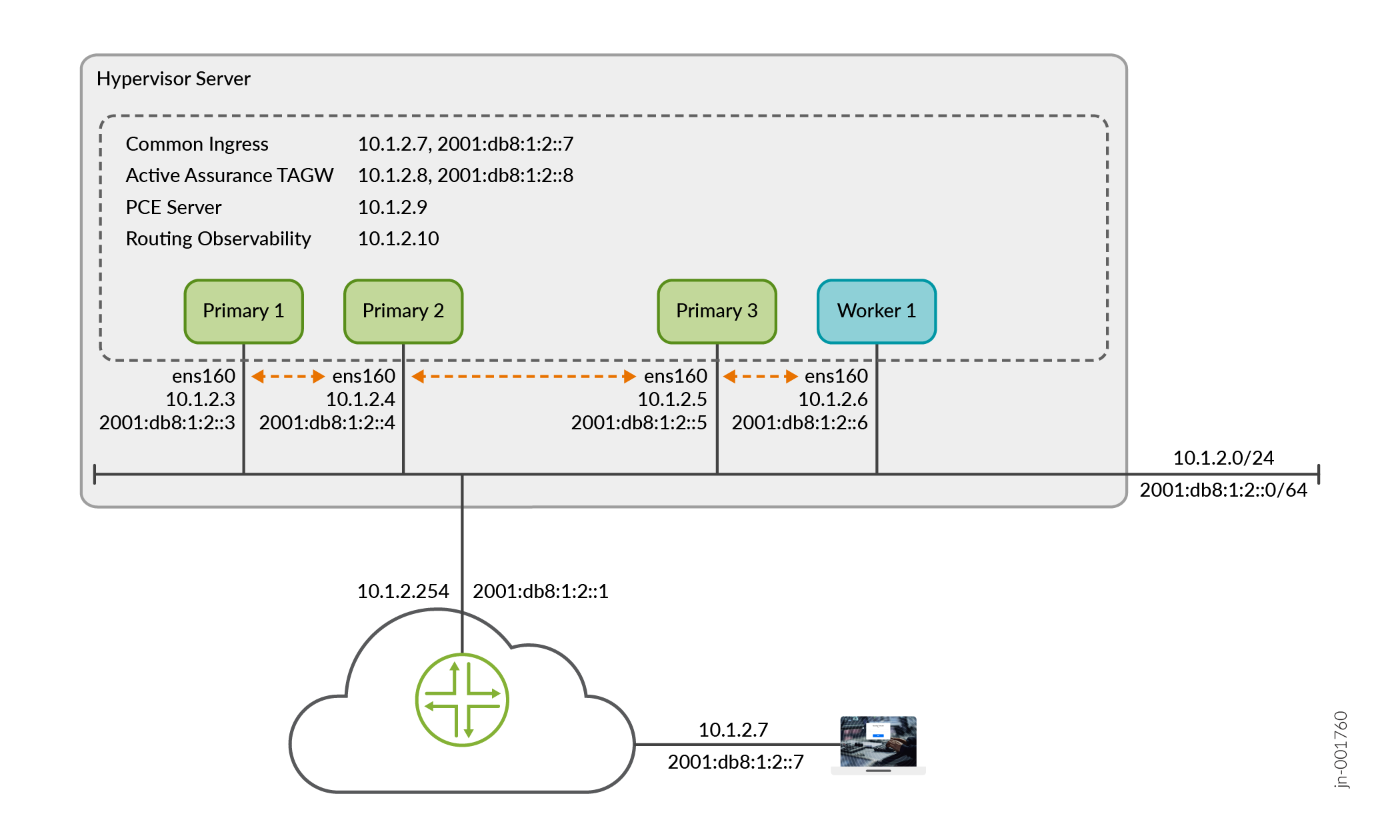
The cluster nodes and VIP addresses can all be on the same subnet with Layer 2 (L2) connectivity between them. IP Addressing Requirements in a Single Subnet Cluster illustrates the IP and VIP addresses within the same subnet required to install a Routing Director deployment cluster on a VM deployment platform.
Cluster in Multiple Subnets
Alternatively, in cases where the cluster nodes are geographically distributed or are located in multiple data centers, the nodes and the VIP addresses can be in different subnets.
On VMware ESXi, KVM, and Proxmox
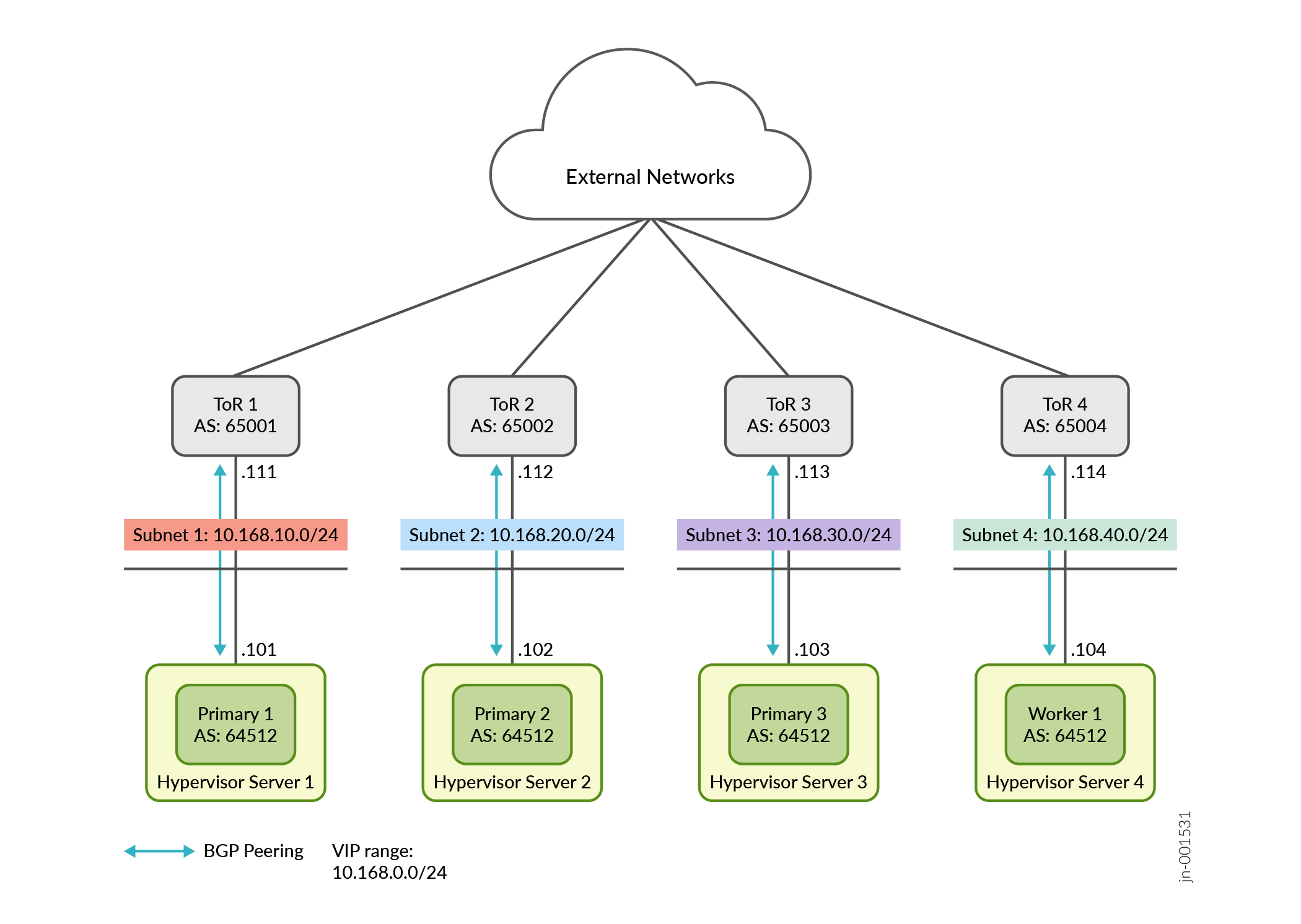
You must configure BGP peering between each cluster node and the respective upstream gateway top-of-rack (ToR) router as well as between the routers. Additionally, the cluster nodes must have the same configured AS number.
Figure 2 illustrates a cluster in four different networks. Each node is served by a dedicated ToR router. In this example, you must configure EBGP using interface peering between the ToR and the corresponding cluster node. Your BGP configuration might differ based on your setup.
In AWS deployments, clusters can be deployed across a single or multiple subnets. Multi-subnet deployments are typically used to support high availability by distributing resources across multiple Availability Zones.
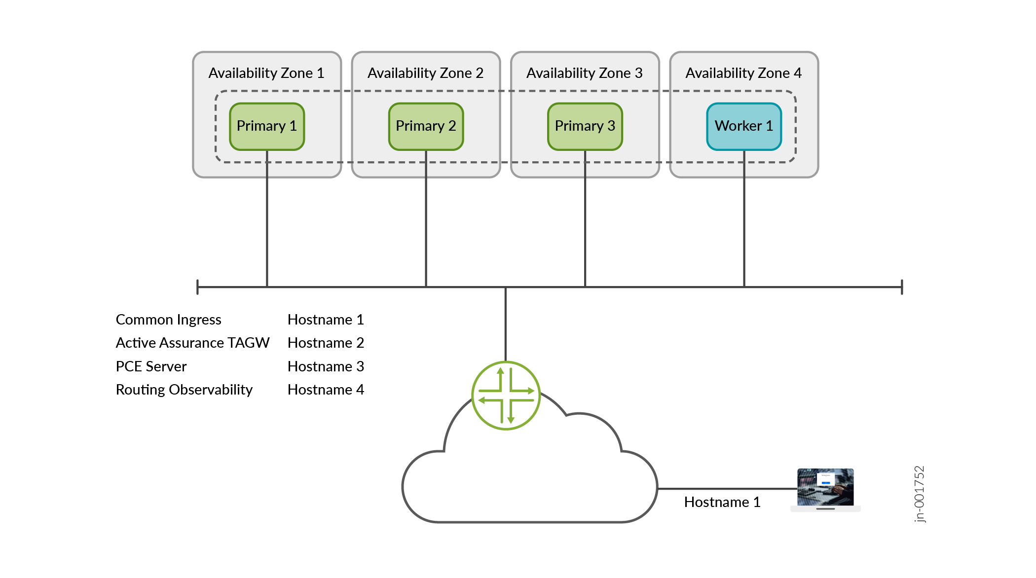
From a configuration perspective, no additional cluster-level setup is required to support multi-subnet deployments, as AWS Load Balancers handle traffic routing and failover. AWS does not require explicit network configuration such as BGP peering or TOR integration.
Cluster with Multiple NICs
When the device‑management network is separate from the network used to access the GUI, you can connect the Routing Director cluster to both networks by assigning each one to a different NIC.
On VMware ESXi, KVM, and Proxmox
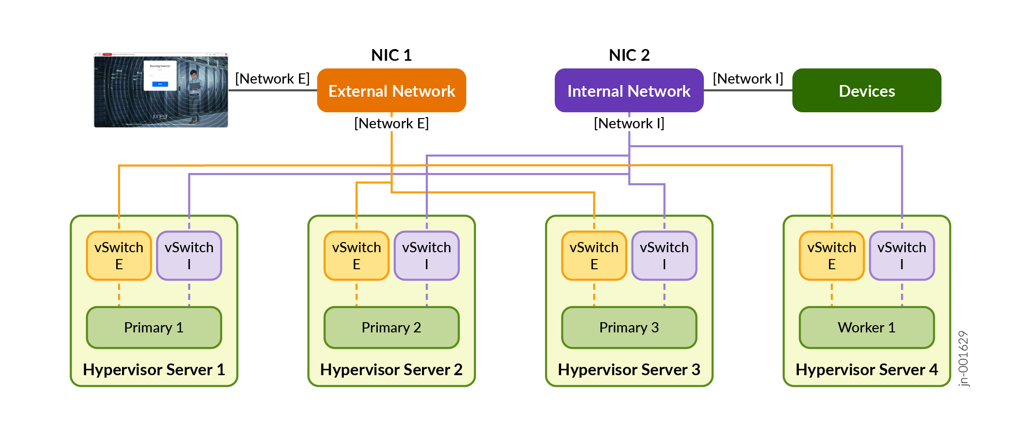
For example, if you have Network A and Network B, each associated with its own NIC, the cluster nodes can connect to both networks using separate generic ingress VIP addresses. The cluster nodes may be installed on one or more hypervisor servers. Although the cluster can be reached through either network’s ingress VIP address, the commonly used design is to dedicate one VIP address for GUI access and the other for NETCONF used to access devices.
To configure Routing Director to connect to multiple networks and multiple NICs, you must configure the generic ingress VIP addresses of both networks. While both the ingress VIP addresses can be used for GUI, NETCONF access, you must explicitly define the VIP address of the network used for device management for NETCONF access. For more information on the commands used, see step 11 in the deploy cluster workflow.
Figure 3 illustrates this deployment model, where the cluster nodes reside on different servers and use two NICs to connect to both the external and internal networks. In this configuration, the GUI is accessed through the external‑network VIP address, while the devices are accessed through the internal‑network VIP address.
On AWS
While AWS instances support multiple network interfaces, the use of dual NIC configurations is not required for typical cluster deployments and has not been qualified.
In most scenarios, network separation (for example, between device management and external GUI access) can be achieved using AWS Load Balancers rather than multiple NICs.
Configure IPv4 Addresses
The following section lists the ports that IPv4 addresses and hostnames that must be available for installation.
On VMware ESXi, KVM, and Proxmox
You need to have the following IP addresses available for the installation.
-
Interface IP addresses, one for each of the nodes.
Note that, in a multi-NIC setup, each NIC must also have individual IP addresses.
Note: Adding worker nodes beyond the documented configuration for increased capacity is not supported in the current deployment architecture. -
Internet gateway IP address
-
Virtual IP (VIP) addresses for:
-
Generic ingress IP address shared between NETCONF (SSH connections from devices) and the Web GUI—This is a general-purpose VIP address that is shared between multiple services and used to access Routing Director from outside the cluster.
Alternatively, when the network used to access the GUI is different from the device‑management network, you can assign one VIP address for Web GUI access and a different VIP address for NETCONF access. When two VIP addresses are configured using the
ingress ingress-vipoption, both the VIP addresses can be used for Web GUI and NETCONF access. However, only the first VIP address specified during configuration is added to the outbound SSH configuration used to adopt devices.To use a different VIP specifically for NETCONF, you must explicitly define that VIP address using the
oc-term
                                oc-term-host
option. Once defined, this VIP address is included in the outbound SSH configuration used to adopt devices from the corresponding network.Although either VIP address can technically be used for GUI and NETCONF access, only the VIP address explicitly defined and configured for NETCONF is added to the outbound SSH configuration.
If devices are in multiple networks, and you need to adopt devices in more than one network, you can manually edit the outbound SSH command to override the configured IP address for NETCONF access.
-
Active Assurance Test Agent gateway (TAGW)—This VIP address serves HTTP-based traffic to the Active Assurance Test Agent endpoint.
-
PCE server—This VIP address is used to establish Path Computational Element Protocol (PCEP) sessions between Routing Director and the devices. The PCE server VIP configuration is necessary to view dynamic topology updates in your network in real-time. For information on establishing BGP-LS peering and PCEP sessions, see Dynamic Topology Workflow.
If your cluster is a multi-subnet cluster, you can also configure multiple VIP addresses, one from each subnet, for the devices to establish PCEP sessions on all VIPs.
-
Routing observability cRPD—This VIP is used by external network devices as BGP Monitoring Protocol (BMP) station IP address to establish the BMP session.
-
Routing observability IPFIX—This VIP is used to collect IPFIX data to view predictor events. Predictor events indicate routing, forwarding, and OS exceptions that are identified by Routing Director as a potential indicator of traffic loss.
The VIP addresses are added to the outbound SSH configuration that is required for a device to establish a connection with Routing Director.
Note: In a multi-subnet cluster installation where the cluster nodes are in different subnets, the VIP addresses must not be on the same subnet as the cluster nodes. -
-
Hostnames mapped to the VIP addresses—Along with VIP addresses, you can also enable devices to connect to Routing Director using hostnames. However, you must ensure that the hostnames and the VIP addresses are correctly mapped in the DNS and your device is able to connect to the DNS. If you configure Routing Director to use hostnames, the hostnames take precedence over VIP addresses and are added to the outbound SSH configuration used during onboarding devices.
On AWS
You need to have the following IP addresses and hostnames available for the installation.
-
Interface IP address for each node in the cluster
-
Internet gateway IP address.
-
Primary and secondary DNS server IPv4 addresses.
-
NTP server information.
-
AWS generated hostnames are available as DNS names when you create the network loadbalancers. You need the following hostnames:
-
Generic ingress hostname shared between NETCONF (SSH connections from devices) and the Web GUI—This is a general-purpose hostname that is shared between multiple services and used to access Routing Director from outside the cluster.
-
Active Assurance Test Agent gateway (TAGW)—This hostname serves HTTP-based traffic to the Active Assurance Test Agent endpoint.
-
PCE server—This hostname address is used to establish Path Computational Element Protocol (PCEP) sessions between Routing Director and the devices. You must resolve this hostname (using the
nslookup
                                        DNS-name
command) to determine the corresponding IP address before you deploy the cluster.The PCE server hostname configuration is necessary to view dynamic topology updates in your network in real-time. For information on establishing BGP-LS peering and PCEP sessions, see Dynamic Topology Workflow.
-
Routing observability cRPD—This hostname is used by external network devices as BGP Monitoring Protocol (BMP) station IP address to establish the BMP session. You must resolve this hostname (using the
nslookup DNS-namecommand) to determine the corresponding IP address before you deploy the cluster. -
Routing observability IPFIX—This hostname is used to collect IPFIX data to view predictor events. Predictor events indicate routing, forwarding, and OS exceptions that are identified by Routing Director as a potential indicator of traffic loss. You must resolve this hostname (using the
nslookup DNS-namecommand) to determine the corresponding IP address before you deploy the cluster.
-
Configure IPv6 Addresses
The following section lists the ports that IPv6 addresses and hostnames that must be available for installation.
On VMware ESXi, KVM, and Proxmox
You can configure the Routing Director deployment cluster using IPv6 addresses in addition to the existing IPv4 addresses. With IPv6 addressing configured, you can use IPv6 addresses for NETCONF, the Active Assurance TAGW, and access to the Web GUI. You must have the following additional addresses available at the time of installation:
-
Interface IPv6 addresses, one for each of the nodes
-
Internet gateway IPv6 address
-
One IPv6 VIP address for generic ingress or two IPv6 VIP addresses, one for the Web GUI and one for NETCONF access
-
One IPv6 VIP address for Active Assurance TAGW
-
Hostnames mapped to the IPv6 VIP addresses—You can also use hostnames to connect to IPv6 addresses. You must ensure that the hostnames are mapped correctly in the DNS to resolve to the IPv6 addresses.
If hostnames are not configured and IPv6 addressing is enabled in the cluster, the IPv6 VIP addresses are added to the outbound SSH configuration, used for device onboarding, instead of IPv4 addresses.
You must configure the IPv6 addresses at the time of cluster deployment. You cannot configure IPv6 addresses after a cluster has been deployed using only IPv4 addresses.
We do not support configuring an IPv6 address for the PCE server and the routing observability feature.
On AWS
IPv6 addresses are not supported for AWS deployments.
Additional IP addresses and hostnames for all deployment platforms
In addition to the listed IP addresses and hostnames, you need to have the following information available with you at the time of installation:
-
Primary and secondary DNS server addresses for IPv4 and IPv6 (if supported)
-
NTP server information
Firewall Requirements
The following section lists the ports that firewalls must allow for communication within and from outside of the cluster.
You must allow intracluster communication between the nodes. In particular, you must keep the ports listed in Table 1 open for communication.
|
Port |
Protocol |
Usage |
From |
To |
Comments |
|---|---|---|---|---|---|
| Infrastructure Ports | |||||
|
22 |
TCP |
SSH for management |
All cluster nodes |
All cluster nodes |
Requires a password or SSH-key |
|
2222 |
TCP |
Deployment Shell configuration sync |
All cluster nodes |
All cluster nodes |
Requires password or SSH-key |
|
443 |
TCP |
HTTPS for registry |
All cluster nodes |
Primary nodes |
Anonymous read access Write access is authenticated |
|
2379 |
TCP |
etcd client port |
Primary nodes |
Primary nodes |
Certificate-based authentication |
|
2380 |
TCP |
etcd peer port |
Primary nodes |
Primary nodes |
Certificate-based authentication |
|
3300 |
TCP |
Ceph mon to all Ceph components |
All cluster nodes |
All cluster nodes |
— |
|
5473 |
TCP |
Calico CNI with Typha |
All cluster nodes |
All cluster nodes |
— |
|
6443 |
TCP |
Kubernetes API |
All cluster nodes |
All cluster nodes |
Certificate-based authentication |
|
6789 |
TCP |
Ceph mon to all Ceph components |
All cluster nodes |
All cluster nodes |
— |
|
6800-7300 |
TCP |
Between all OSDs and all other daemons and clients |
All cluster nodes |
All cluster nodes |
— |
|
7472 |
TCP |
MetalLB metric port |
All cluster nodes |
All cluster nodes |
Anonymous read only, no write access |
|
7946 |
UDP |
MetalLB member election port |
All cluster nodes |
All cluster nodes |
— |
| 8443 |
TCP |
HTTPS for registry data sync |
Primary nodes |
Primary nodes |
Anonymous read access Write access is authenticated |
|
9345 |
TCP |
rke2-server |
All cluster nodes |
All cluster nodes |
Token based authentication |
|
10250 |
TCP |
kubelet metrics |
All cluster nodes |
All cluster nodes |
Standard Kubernetes authentication |
|
10260 |
TCP |
RKE2 cloud controller |
All cluster nodes |
All cluster nodes |
Standard Kubernetes authentication |
|
32766 |
TCP |
Kubernetes node check for PCE service local traffic policy |
All cluster nodes |
All cluster nodes |
Read access only |
|
Calico CNI Ports |
|||||
|
4789 |
UDP |
Calico CNI with VXLAN |
All cluster nodes |
All cluster nodes |
— |
|
5473 |
TCP |
Calico CNI with Typha |
All cluster nodes |
All cluster nodes |
— |
|
51820 |
UDP |
Calico CNI with Wireguard |
All cluster nodes |
All cluster nodes |
— |
The following ports must be open for communication from outside the cluster.
| Port |
Protocol |
Usage |
From |
To |
|---|---|---|---|---|
|
172 |
UDP |
SNMP trap |
External network devices |
Web GUI Ingress VIP address(es) |
|
179 |
TCP |
Topology visualization and traffic engineering using the topology information |
Routing Director deployment cluster node IP address |
Router IP address to which you want to set up BGP peering from Routing Director. You can use the router management IP address or the router interface IP address. |
|
443 |
TCP |
Web GUI + API |
External user computer/desktop |
Web GUI Ingress VIP address(es) |
|
443 |
TCP |
Active Assurance Test Agent |
External network devices |
Active Assurance Test Agent VIP address |
|
2200 |
TCP |
NETCONF |
External network devices |
Web GUI Ingress VIP address(es) |
|
4189 |
TCP |
PCE Server |
External network devices |
PCE Server VIP address |
|
4739 |
UDP |
Routing Observability |
External network devices |
IPFIX VIP address |
|
6800 |
TCP |
Active Assurance Test Agent |
External network devices |
Active Assurance Test Agent VIP address |
|
17002 |
TCP |
Routing Observability |
External network devices |
Routing observability cRPD load balancer IP address |
|
32767 Port must be opened on the device side. |
TCP |
gNMI |
Routing Director deployment cluster node IP address |
External network devices |
On AWS
The following table details the security group that is applied to the AWS load balancer to allow intracluster communication between the nodes.
| Direction | Protocol/Port | Source/Destination | Description |
|---|---|---|---|
|
Inbound |
TCP/443 |
0.0.0.0/0 |
For access to the GUI. Allow from everywhere |
|
Inbound |
TCP/2200 |
0.0.0.0/0 |
For NETCONF access. Allow traffic from the load balancer to the VM. |
|
Inbound |
TCP/4189 |
0.0.0.0/0 |
For PCEP |
|
Inbound |
UDP/4739 |
0.0.0.0/0 |
For routing observability CRPD |
|
Inbound |
TCP/5432 |
0.0.0.0/0 |
For routing observability IPFIX health-check |
|
Inbound |
TCP/6800 |
0.0.0.0/0 |
For active assurance TAGW |
|
Inbound |
TCP/17002 |
0.0.0.0/0 |
For routing observability IPFIX |
|
Inbound |
UDP/162 |
0.0.0.0/0 |
For SNMP trap |
|
Outbound |
any |
any |
Allow all outbound traffic from the VMs |
The following table details the security group that is attached to the EC2 instance and allows traffic flow to and from the VMs.
| Direction | Protocol/Port | Source/Destination | Description |
|---|---|---|---|
|
Inbound |
TCP/22 |
0.0.0.0/0 |
For all SSH management |
|
Inbound |
TCP/30011-30024 |
0.0.0.0/0 |
NodePort; to allow connection from the routers and the source-IP addresses to connect to the GUI. |
|
Inbound |
any |
VPC subnet IP range |
Allow all intra-VPC communication between the VMs. |
|
Outbound |
any |
any |
Allow all outbound traffic from the VMs |
Any form of NAT, IP masquerading, or address translation between cluster VMs is not supported and must be disabled.
Web Browser Requirements
The latest versions of Google Chrome, Mozilla Firefox, and Safari.
We recommend that you use Google Chrome.
What's Next
To install Routing Director, go to Install on KVM, Proxmox VE, and VMware ESXi or Install on AWS, depending on your VM deployment platform.