Help us improve your experience.

Let us know what you think.

Do you have time for a two-minute survey?


Cloud-Native Router Operator Service Module: Host-Based Routing

The Cloud-Native Router Operator Service Module is an operator framework that we use to develop cRPD applications and solutions. This section describes how to use the Service Module to implement a host-based routing solution for your Kubernetes cluster.

Overview

We provide the Cloud-Native Router Operator Service Module to implement a cRPD host-based routing solution for your Kubernetes cluster. Host-based routing, also known as host-based networking, refers to using the host's network namespace instead of the Kubernetes default namespace for the pod network. In the context of Cloud-Native Router, this means that pod-to-pod traffic traverses an external (to the cluster) network provided by cRPD.

The Kubernetes CNI exposes container network endpoints through BGP to a co-located (but independent) cRPD instance acting as a BGP peer. Packets between pods are routed by the Kubernetes CNI to this cRPD instance. This cRPD instance, in turn, routes the packets to the cRPD instance on the destination node for hand-off to the destination Kubernetes CNI for delivery to the destination pod.

By taking this approach to Kubernetes host networking, we are leveraging Cloud-Native Router to provide a more fulsome pod networking implementation that supports common data center protocols such as EVPN-VXLAN and MPLS over UDP.

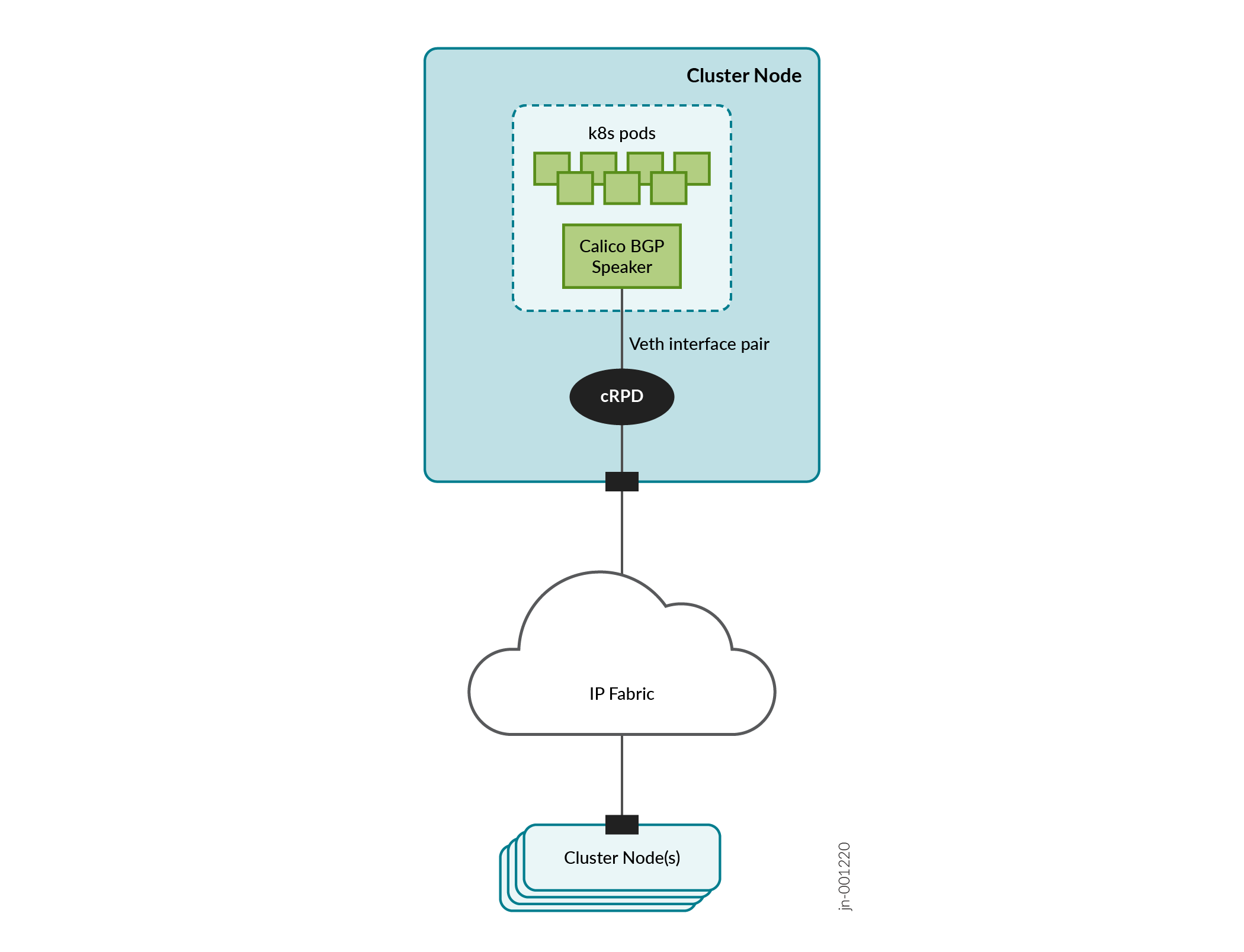
Figure 1 shows a Kubernetes cluster leveraging cRPD for host-based routing. The Calico BGP speaker in the cluster connects through a virtual Ethernet (veth) interface to a co-located cRPD instance attached to the IP fabric interconnecting cluster nodes.

Figure 1: Host-Based Routing Host-Based Routing

To facilitate the installation of this host-based routing solution, we provide a Helm chart that you can install and we show you how to configure and customize cRPD and the underlying network infrastructure to support a 5-node cluster (3 control plane nodes and 2 worker nodes).

Install Host-Based Routing

This is the main procedure. Start here.
  1. Prepare the Nodes.
  2. Create Virtual Ethernet Interface (VETH) Pairs and Configure Static Routes.
  3. Pick one of the control plane nodes as the installation host and install Helm on it. The installation host is where you'll install the Helm chart.
  4. Install cRPD on all nodes.

    For convenience, we provide an example script (Example cRPD Installation Script) that installs cRPD on a node. Run the script with the respective configuration file on each node.

    For more information on how to install cRPD, see https://www.juniper.net/documentation/us/en/software/crpd/crpd-deployment/index.html.

  5. Verify that the veth-crpd interface is reachable from the local host.
    For example:
  6. Verify that BGP sessions are established between cRPDs and check the routing table.
    1. Exec into the cRPD container on the local node.
      where <crpd-container> is the name of the cRPD container running on the local node.
    2. Enter CLI mode.
    3. Check that BGP sessions have been established.
      If you're on a control plane node, then you'll see BGP sessions established between the local cRPD instance and the cRPD instances on all other nodes. If you're on a worker node, then you'll see BGP sessions established between the local cRPD instance and the cRPD instances on all the control plane nodes.
    4. Check that veth-k8s routes are in the routing table.
      Make sure that the veth-k8s routes (for example, 10.1.1.1, 10.1.2.1, 10.1.3.1, 10.1.4.1, 10.1.5.1) are in the routing table.
  7. Verify that veth-k8s interfaces are reachable from each node to all other nodes.
    For example:
  8. Configure the kubelet on all nodes to use the local veth-k8s IPv4 address as the node IP.
    where <veth-k8s-ip> is the <veth-k8s> IPv4 address as shown in Table 1 (minus the /30 subnet qualifier). Perform this step on all nodes, but use the respective <veth-k8s> IPv4 addresses.
  9. Create the first control plane node in the Kubernetes cluster.
    Log in to one of the control plane nodes and create the cluster.

    where <pod-cidr> is 192.168.0.0/24 in our example (or if running dual stack 192.168.0.0/24,2001:db8:42:0::56),

    and <veth-k8s-ip> is the <veth-k8s> IPv4 address of the local control plane node.

  10. Log in to each of the other two control plane nodes and join each to the cluster.
    For example:
  11. Log in to each of the two worker nodes and join each to the cluster.
    For example:
  12. Verify that all nodes are now part of the cluster.
  13. Untaint all control plane nodes so that all pods can run on them.
  14. Install Calico.
  15. Configure Calico.
    1. Disable nodeMesh and set the AS number and listen port.
    2. Configure the IPv4 address pool with no IP-IP or VxLAN encapsulation.
    3. (Optional) If you're running a dual stack setup, then configure the IPv6 address pool.
    4. Configure the IPv4 BGP peering relationships.
    5. (Optional) If you're running a dual stack setup, then configure the IPv6 BGP peering relationships.
  16. Verify that BGP sessions are established between the Calico CNI and the co-located cRPD.
    1. Exec into the cRPD container on the local node.
      where <crpd-container> is the name of the cRPD container running on the local node.
    2. Enter CLI mode.
    3. Check that BGP sessions have been established.
      In addition to the BGP sessions that you saw earlier between cRPDs, you'll see a BGP session established between the local cRPD and the Calico CNI.
  17. Install the Operator Service Module.
  18. (Optional) If you want to set up a secondary CNI that also uses cRPD, then see Set Up Secondary CNI for Host-Based Routing.

Prepare the Nodes

Perform the following steps on all the nodes (VMs or bare metal servers) that you want to be in your cluster. All nodes should have at least 2 interfaces:
  • one interface for regular management access (for example, SSH)

  • one interface for cRPD to connect to the IP fabric

  1. Install a fresh OS.
    We tested our host-based routing solution on the following combination:
    • Ubuntu 22.04

    • Linux kernel 5.15.0-88-generic

  2. Update the repository list and install podman.
  3. Install the required kernel modules on all nodes in the cluster.
    Create /etc/modules-load.d/jcnr.conf and populate it with the following list of kernel modules:
  4. Enable IP forwarding and iptables on the underlay Linux bridges.
    Create /etc/sysctl.d/99-kubernetes-cri.conf and populate it with the following configuration:Additionally, set the following in /etc/sysctl.conf:
    Note:

    The above enables IP forwarding and iptables for both IPv4 and IPv6. If you're only running IPv4, then omit the IPv6 settings.

  5. Set the MAC address policy.
  6. Install kubeadm, kubelet, and kubectl. See https://kubernetes.io/docs/setup/production-environment/tools/kubeadm/install-kubeadm/.
    We tested our host-based routing solution on Kubernetes version 1.28.15.
  7. Reboot.

Create Virtual Ethernet Interface (VETH) Pairs and Configure Static Routes

Before we bring up the Kubenetes cluster and cRPD, we'll create the veth interfaces that connect them together and configure static routes to direct traffic to the cRPD instance.

On each node, we'll run the Kubernetes cluster (including the Calico BGP speaker) in the Kubernetes default namespace and we'll run cRPD in a namespace that we'll call crpd. We'll create a veth pair that connects the two namespaces, from veth-k8s in the default namespace to veth-crpd in the crpd namespace.

This is shown in Table 1 along with the IP address assignments we'll use in our example. This includes both IPv4 and IPv6 addresses for a dual stack deployment. If you're only running IPv4, then ignore the IPv6 settings.

Table 1: Namespace and Interface Configuration (Example)

Node

Namespace

Interface

IP Address

Node 1 (control plane)

default

veth-k8s

10.1.1.1/30

2001:db8:1::1/126

crpd

veth-crpd

10.1.1.2/30

2001:db8:1::2/126

ens41

192.168.1.101/24

Node 2 (control plane)

default

veth-k8s

10.1.2.1/30

2001:db8:2::1/126

crpd

veth-crpd

10.1.2.2/30

2001:db8:2::2/126

ens41

192.168.1.102/24

Node 3 (control plane)

default

veth-k8s

10.1.3.1/30

2001:db8:3::1/126

crpd

veth-crpd

10.1.3.2/30

2001:db8:2::2/126

ens41

192.168.1.103/24

Node 4 (worker)

default

veth-k8s

10.1.4.1/30

2001:db8:4::1/126

crpd

veth-crpd

10.1.4.2/30

2001:db8:4::2/126

ens41

192.168.1.104

Node 5 (worker)

default

veth-k8s

10.1.5.1/30

2001:db8:5::1/126

crpd

veth-crpd

10.1.5.2/30

2001:db8:5::2/126

ens41

192.168.1.105/24

1 This is the physical underlay interface connecting cRPD to the IP fabric. The interface name in your setup may differ.

Perform the following steps on all nodes in the cluster. Remember to set the IP addresses for the different nodes as shown in Table 1.

  1. Create veth-k8s and veth-crpd and pair them together.
    1. Create the veth interface pair.
      By default, both interfaces are in the default namespace. We'll move veth-crpd to the crpd namespace in a later step.
    2. Enable these 2 veth interfaces.
    3. Configure the IP address on the veth-k8s interface.

      We'll configure the IP address for the veth-crpd interface in a later step.

    4. (Optional) If you want to run a dual IPv4/IPv6 stack setup, then configure the IPv6 address on the same veth-k8s interface.

      We'll configure the IPv6 address for the veth-crpd interface in a later step.

  2. Create the crpd namespace for cRPD.
  3. Move veth-crpd to the crpd namespace.
    1. Assign the physical underlay interface to the crpd namespace. This is the interface that connects cRPD to the IP fabric.
      For example:where ens4 is the physical interface (in our example) that connects to the IP fabric.
    2. Configure the IP address for the ens4 interface.
      where 192.168.1.0/24 is the underlay subnet connecting to the IP fabric.
    3. Assign the veth-crpd interface to the crpd namespace.
    4. Configure the IP address for the veth-crpd interface.
    5. (Optional) If you want to run a dual IPv4/IPv6 stack setup, then configure the IPv6 address for the veth-crpd interface.
  4. In the default namespace, configure a route to all cRPD interfaces.
  5. Repeat step 1 through step 4 for Nodes 2 through 5 according to Table 1.

Install the Operator Service Module

Run these steps on the nodes indicated. The installation host is the control plane node where you installed Helm earlier.
  1. On the installation host, create the jcnr namespace.
  2. On the installation host, create and apply the JCNR secret.
    Create a jcnr-secrets.yaml file with the below contents.

    where <password> is the base64-encoded string of the root password and <crpd-license> is the base64-encoded cRPD license. For more information on installing your cRPD license, see Installing Your License.

    Apply the secret.

  3. On all nodes, create /etc/crpd/crpd_conf.yaml with the content below.
    where <veth-crpd-ip> is the IPv4 address of the <veth-crpd> interface on the local node.
  4. On the installation host, download the Cloud-Native Router Operator Service Module package.

    You can download the Service Module package from the Juniper Networks software download site. See Cloud-Native Router Software Download Packages.

  5. Gunzip and untar the software package.
  6. Load the provided images on all nodes in the cluster. The images are located in the downloaded package.
  7. On the installation host, extract the Cloud-Native Operator Service Module Helm chart.
    1. Navigate to the Helm chart directory.
    2. Extract the Helm chart.
  8. Apply the Helm chart.
    Set the replicaCount to the number of control plane nodes in the cluster.
  9. After a few minutes, verify that the cluster is up and running.

Set Up Secondary CNI for Host-Based Routing

This procedure shows an example of how to set up a secondary MACVLAN CNI and a secondary IPVLAN CNI for host-based routing.
  1. On the installation host, install multus.
  2. On all nodes, create the veth interface pairs for MACVLAN.
    where host-end is the veth endpoint on the Kubernetes cluster and vrf-end is the veth endpoint on cRPD.
  3. On all nodes, create the veth interface pairs for IPVLAN.
    where ipvlan-host is the veth endpoint on the Kubernetes cluster and ipvlan-vrf is the veth endpoint on cRPD.
  4. For IPVLAN, on all nodes, enable proxy ARP on ipvlan-vrf.
  5. Check the interfaces on all nodes.
    If, for some reason, the interfaces are not up, set them up from cRPD as follows:
  6. On the installation host, create and apply the default VxLAN and route target pools.
  7. Label all the nodes.
    where <cp-nodename> and <worker-nodename> are the node names of the control plane and worker nodes respectively.
  8. Configure JCNR.
  9. Apply the MACVLAN custom resource.
  10. Create MACVLAN pods.
  11. Apply the IPVLAN custom resource.
  12. Create IPVLAN pods.