SRX5400 Power System
SRX5400 Firewall Power System Overview
The firewall uses either AC or DC power supplies.
The SRX5400 Firewall and SRX5600 Firewall use the same power supply model.
The firewall is configurable with two, three, or four AC power supplies by default (optionally, a fourth power supply can be added) or two DC power supplies. The AC power supplies are located horizontally at the rear of the chassis in slots PEM0 through PEM3 (left to right) and the DC power supplies are located in slots PEM0 and PEM2. The power supplies connect to the midplane, which distributes the different output voltages produced by the power supplies to the firewall components, depending on their voltage requirements. Each power supply is cooled by its own internal cooling system.
The firewall cannot be powered from AC and DC power supplies simultaneously. The first type of power supply detected by the firewall when initially powered on determines the type of power supply allowed by the firewall. All installed power supplies of the other type are disabled by the firewall. If you install a power supply of the other type while the firewall is operating, the firewall disables the power supply and generates an alarm.
Redundant power supplies are hot-removable and hot-insertable. When you remove a power supply from a firewall that uses a nonredundant power supply configuration, the firewall might shut down depending on your configuration.
Table 1 summarizes the available power supply types, their output capacities, and their redundancy and power distribution schemes. For detailed power supply specifications, see SRX5400 Firewall AC Power Supply Specifications or SRX5400 Firewall DC Power Supply Specifications.
Power Supply Type |
Input Condition (If Any) |
Maximum Output |
Redundancy |
|---|---|---|---|
AC |
Low-line (110 V Input) |
1167 W |
2+1 |
High-line (220 V Input) |
2050 W |
|
|
DC |
DIP=0 (60 A Input) |
2240 W |
1+1 |
DIP=1 (80 A Input) |
2440 W |
1+1 |
In all power supply configurations, the power distribution and total power is shared by all of the components in the firewall chassis. The power supplies are guaranteed to provide adequate power to the system. In the low-line (110VAC input) and high-line (220VAC input) configurations, two power supplies are required to support the firewall electrical requirements.
There are no slot restrictions for AC power supplies. If you are using DC power supplies, then use the slots as shown in Table 2.
PSU |
Minimum PSU Requirement |
PEM Slot |
PSU Redundancy Requirements |
PEM Slot |
|---|---|---|---|---|
110V AC PSU |
2 |
Any |
3 |
Any |
220V AC PSU |
2 |
Any |
|
Any |
DC PSU |
1 |
PEM0 & PEM2 |
2 |
PEM2 |
SRX5400 Firewall AC Power Supply
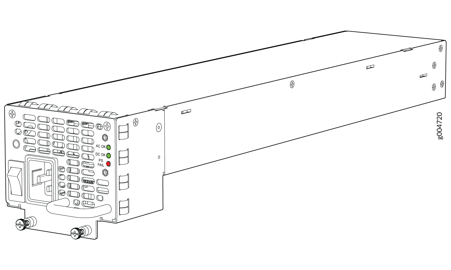
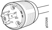
Each AC power supply consists of one AC appliance inlet, an AC switch, a fan, and LEDs to monitor the status of the power supply. Figure 1 shows the power supply. Each inlet requires a dedicated AC power feed and a dedicated 16 A @ 100 VAC or 16 A @ 200 VAC circuit breaker, or as required by local code.
The firewall is pluggable type A equipment installed in a restricted-access location. It has a separate protective earthing terminal (sized for UNC 1/4-20 ground lugs) provided on the chassis in addition to the grounding pin of the power supply cord. This separate protective earthing terminal must be permanently connected to earth.
The SRX5400 Firewall and SRX5600 Firewall use the same power supply model.
SRX5400 Firewall AC Power Supply Specifications
Table 3 lists the AC power supply electrical specifications.
Table 4 lists the AC power system electrical specifications.
Item |
Specification |
|---|---|
Maximum output power |
1167 W (low line) 2050 W (high line) |
AC input current rating |
16 A @ 110 VAC maximum 15.1 A @ 200 VAC maximum |
AC input voltage |
Operating range: 100 - 240 VAC (nominal) |
AC input line frequency |
50 to 60 Hz (nominal) |
Item |
Low-Line (110V) |
High-Line (220V) |
|---|---|---|
Redundancy |
2+1 |
|
Output power (maximum) per power supply |
1167 W |
2050 W |
Output power (maximum) per system |
3501 W |
4100 W |
SRX5400 Firewall AC Power Supply LEDs
Each AC power supply faceplate contains three LEDs that indicate the status of the power supply (see Table 5). The power supply status is also reflected in two LEDs on the craft interface. In addition, a power supply failure triggers the major alarm LED on the craft interface.
Label |
Color |
State |
Description |
|---|---|---|---|
AC OK |
Amber |
Off |
AC power input voltage is below 78 VAC. |
Green |
On |
AC power input voltage is within 78–264 VAC. |
|
DC OK |
Green |
Off |
DC power outputs generated by the power supply are not within the normal operating ranges. |
On |
DC power outputs generated by the power supply are within the normal operating ranges. |
||
PS FAIL |
Red |
Off |
Power supply is functioning normally. |
On |
Power supply is not functioning normally and its output voltage is out of regulation limits. Check AC OK and DC OK LEDs for more information. |
AC Power Cord Specifications for the SRX5400 Firewall
Each AC power supply has a single AC appliance inlet located on the power supply that requires a dedicated AC power feed. Most sites distribute power through a main conduit that leads to frame-mounted power distribution panels, one of which can be located at the top of the rack that houses the firewall. An AC power cord connects each power supply to the power distribution panel.
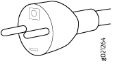
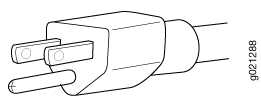
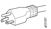
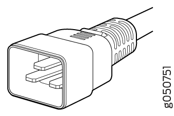
The firewall is not shipped with AC power cords. You must order power cords separately using the model number shown in Table 6. The C19 appliance coupler end of the cord see Figure 2, inserts into the AC appliance inlet coupler, type C20 (right angle) as described by International Electrotechnical Commission (IEC) standard 60320. The plug end of the power cord fits into the power source receptacle that is standard for your geographical location.
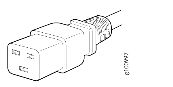
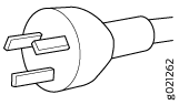
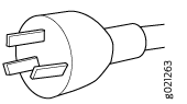
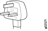
Table 6 provides specifications and depicts the plug on the AC power cord provided for each country or region.
|
Country |
Model Number |
Electrical Specification |
Plug Type |
Graphic |
|---|---|---|---|---|
|
Australia |
CBL-M-PWR-RA-AU |
240 VAC, 50 Hz AC |
SAA/3/15 |
|
|
China |
CBL-M-PWR-RA-CH |
220 VAC, 50 Hz AC |
CH2-16P |
|
|
Europe (except Denmark, Italy, Switzerland, and United Kingdom) |
CBL-M-PWR-RA-EU |
220 or 230 VAC, 50 Hz AC |
CEE 7/7 |
|
|
Italy |
CBL-M-PWR-RA-IT |
230 VAC, 50 Hz AC |
CEI 23-16/VII |
|
|
Japan |
CBL-PWR-RA-JP15 |
125 VAC, 50 or 60 Hz AC |
JIS 8303 |
|
|
CBL-M-PWR-RA-JP |
220 VAC, 50 or 60 Hz AC |
NEMA L6-20P |
|
|
|
North America |
CBL-PWR-RA-US15 |
125 VAC, 60 Hz AC |
NEMA 5-15P |
|
|
CBL-PWR-RA-TWLK-US15 |
125 VAC, 60 Hz AC |
NEMA L5-15P |
|
|
|
CBL-M-PWR-RA-US |
250 VAC, 60 Hz AC |
NEMA 6-20 |
|
|
|
CBL-M-PWR-RA-TWLK-US |
250 VAC, 60 Hz AC |
NEMA L6-20P |
|
|
|
United Kingdom |
CBL-M-PWR-RA-UK |
240 VAC, 50 Hz AC |
BS89/13 |
|
|
Worldwide (except Japan) |
CBL-EX-PWR-C19-C20 |
240 VAC, 50 Hz AC |
EN 60320-2-2/1 |
|

The AC power cord for the firewall is intended for use with the firewall only and not for any other use.
To meet safety and electromagnetic interference (EMI) requirements and to ensure proper operation, you must properly ground the firewall chassis before connecting power. See Grounding the SRX5400 Firewall for instructions.
Power cords and cables must not block access to device components or drape where people could trip on them.
In North America, AC power cords must not exceed 4.5 m (approximately 14.75 ft) in length, to comply with National Electrical Code (NEC) Sections 400-8 (NFPA 75, 5-2.2) and 210-52, and Canadian Electrical Code (CEC) Section 4-010(3). The cords listed in Table 6 are in compliance.
AC Power Circuit Breaker Requirements for the SRX5400 Firewall
Each AC power supply has a single AC appliance inlet located on the power supply that requires a dedicated AC power feed. We recommend that you use a customer site circuit breaker rated for 15 A (250 VAC) minimum for each AC power supply, or as required by local code. Doing so enables you to operate the firewall in any configuration without upgrading the power infrastructure.
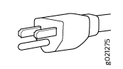
SRX5400 Firewall DC Power Supply
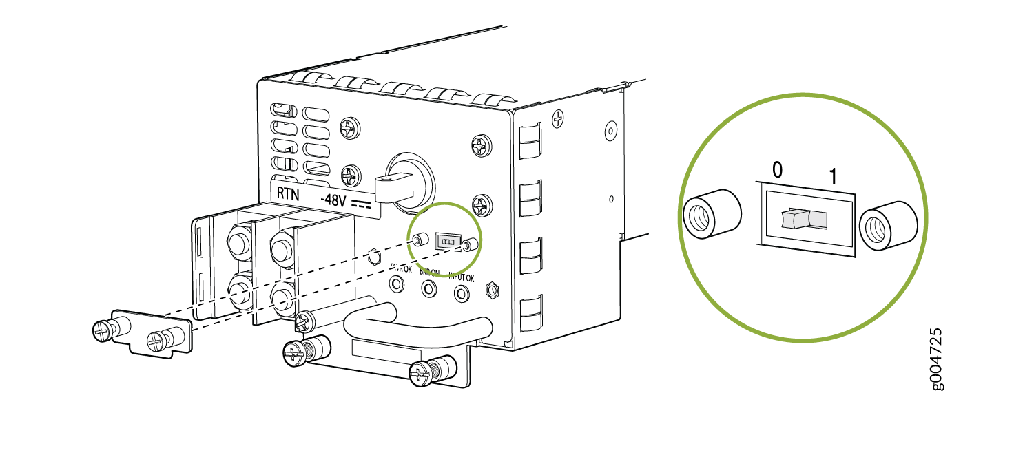
Each DC power supply consists of one DC input (–48 VDC and return), one 40 A (–48 VDC) circuit breaker, a fan, and LEDs to monitor the status of the power supply. Figure 3 shows the power supply. Each DC power supply has a single DC input (–48 VDC and return) that requires a dedicated facility circuit breaker.
We recommend that you provision 60 A or 70 A per feed, depending on the selected DIP switch setting.
The SRX5400 Firewall and SRX5600 Firewall use the same power supply model.
SRX5400 Firewall DC Power Supply Specifications
Table 7 lists the DC power supply electrical specifications. Table 8 lists the DC power system specifications.
Item |
Specification |
|
|---|---|---|
DIP=0 (60 A Input) |
DIP=1 (80 A Input) |
|
Maximum output power |
2400 W |
2600 W |
DC input voltage |
Minimum: –40.5 VDC Nominal: –48 VDC Operating range: –40.5 to –72 VDC |
|
DC input current rating |
50 A @ –48 V nominal operating voltage |
54.2 A @ –48 V nominal operating voltage |
Internal Supplementary Protector |
None |
None |
Item |
Specification |
|
|---|---|---|
DIP=0 (60 A Input) |
DIP=1 (80 A Input) |
|
Redundancy |
1+1 |
1+1 |
Output power (maximum) per power supply |
2400 W |
2600 W |
Output power (maximum) per system |
2400 W |
2600 W |
SRX5400 Firewall DC Power Supply LEDs
Each DC power supply faceplate contains three LEDs that indicate the status of the power supply (see Table 9). In addition, a power supply failure triggers the major alarm LED on the craft interface.
The SCB must be present for the PWR OK LED to go on.
Label |
Color |
State |
Description |
|---|---|---|---|
PWR OK |
Green |
Off |
Power supply is not functioning normally. Check the INPUT OK LED for more information. |
On |
Power supply is functioning normally. |
||
Amber |
On |
The main output voltage is out of range (lower limit: 37.5 V to 39.5 V; upper limit: 72.5 V to 76 V). |
|
BRKR ON |
Green |
Off |
DC power supply circuit breaker is turned off. |
Green |
On |
DC power input is present and the DC power supply circuit breaker is turned on. |
|
INPUT OK |
Green |
Off |
DC input to the PEM is not present. |
On |
DC input is present and is connected in correct polarity. |
||
Amber |
On |
DC input is present, but not in valid operating range or connected in reverse polarity. |
DC Power Cable Specifications for the SRX5400 Firewall
Table 10 summarizes the specifications for the power cables, which you must supply.
Cable Type |
Quantity |
Specification |
|---|---|---|
Power |
Four 6-AWG (13.3 mm2) cables for each power supply |
Minimum 60°C wire, or as required by the local code |
You must ensure that power connections maintain the proper polarity. The power source cables might be labeled (+) and (–) to indicate their polarity. There is no standard color coding for DC power cables. The color coding used by the external DC power source at your site determines the color coding for the leads on the power cables that attach to the terminal studs on each power supply.
DC Power Cable Lug Specifications for the SRX5400 Firewall
The accessory box shipped with the firewall includes the cable lugs that attach to the terminal studs of each power supply (see Figure 4).
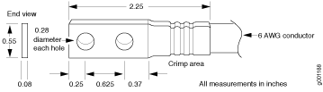
Before firewall installation begins, a licensed electrician must attach a cable lug to the grounding and power cables that you supply. A cable with an incorrectly attached lug can damage the firewall.
The firewall is a pluggable type A equipment installed in restricted access location. It has a separate protective earthing terminal [Metric -M6 and English - ¼-20 screw) ground lugs] provided on the chassis. This separate protective earth terminal must be permanently connected to earth.
DC Power Circuit Breaker Requirements for the SRX5400 Firewall
Each DC power supply has a single DC input (–48 VDC and return) that requires a dedicated facility circuit breaker. We recommend that you use a customer site circuit breaker rated for 40 A (–48 VDC) minimum for each DC power supply, or as required by local code. Doing so enables you to operate the firewall in any configuration without upgrading the power infrastructure.
If you plan to operate a DC-powered firewall at less than the maximum configuration and do not provision a 40 A (–48 VDC) circuit breaker, we recommend that you provision a circuit breaker for each DC power supply rated for at least 125% of the continuous current that the system draws at –48 VDC, or as required by local code.
DC Power Source Cabling for the SRX5400 Firewall
Figure 5 shows a typical DC source cabling arrangement.
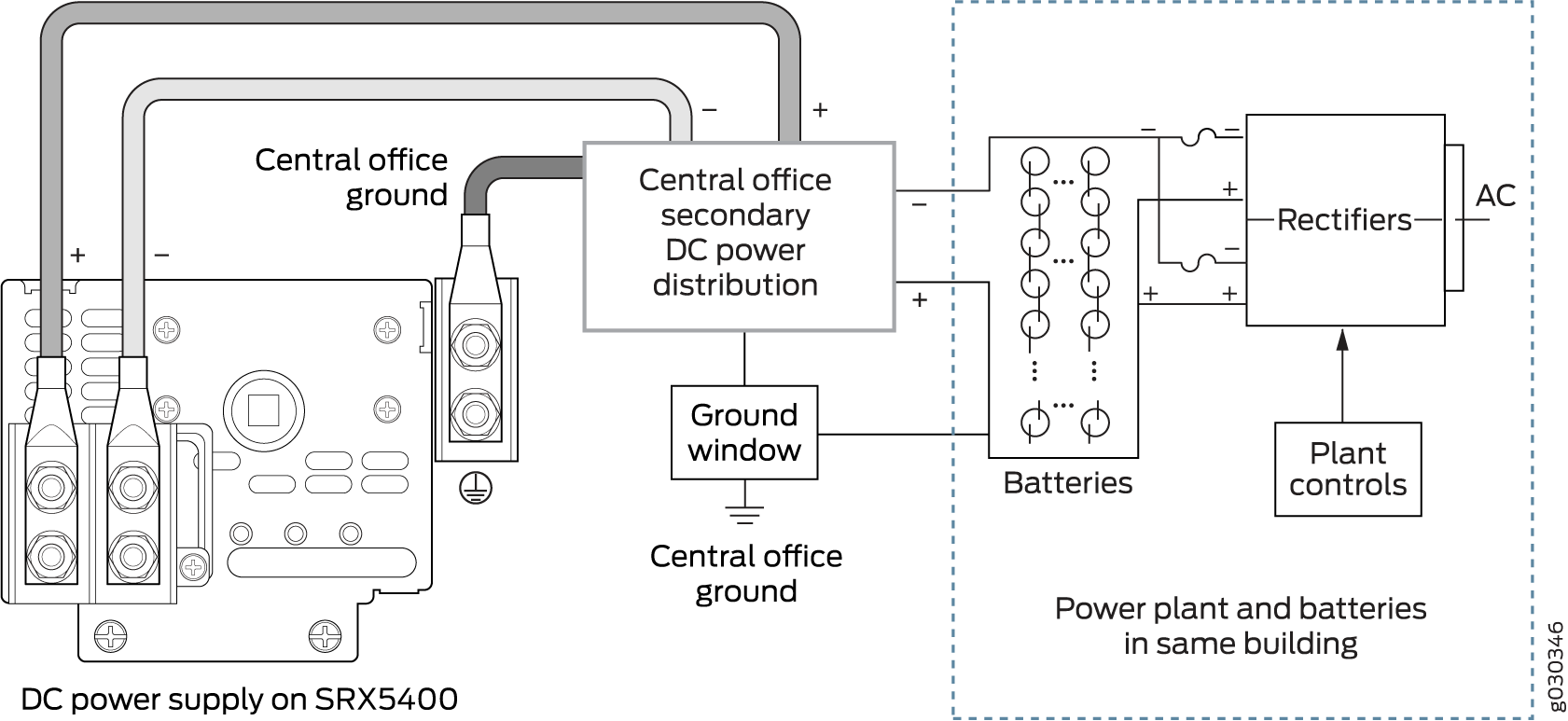
The DC power supplies must be powered by dedicated power feeds.
You must ensure that power connections maintain the proper polarity. The power source cables might be labeled (+) and (–) to indicate their polarity. There is no standard color coding for DC power cables. The color coding used by the external DC power source at your site determines the color coding for the leads on the power cables that attach to the terminal studs on each power supply.
For field-wiring connections, use copper conductors only.
Power cords and cables must not block access to device components or drape where people could trip on them.
SRX5400 Firewall Chassis Grounding Point Specifications
To meet safety and electromagnetic interference (EMI) requirements and to ensure proper operation, you must properly ground the firewall chassis before connecting power. See Grounding the SRX5400 Firewall for instructions.
Before firewall installation begins, a licensed electrician must attach cable lugs to the grounding and power cables that you supply. A cable with an incorrectly attached lug can damage the firewall.
The firewall chassis has one grounding point at the upper right corner of the back panel. The grounding point consists of two threaded holes spaced 0.625-in. (15.86-mm) apart (Figure 6). The grounding point holes fit UNC 1/4–20 screws. The accessory box shipped with the firewall includes the cable lug that attaches to the grounding cable and two UNC 1/4–20 screws used to secure the grounding cable to the firewall grounding point.
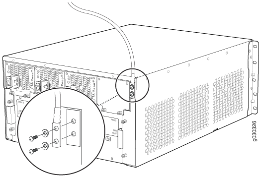
To ground the firewall, you must connect a grounding cable to earth ground and then attach it to the chassis grounding point using the two screws provided.
Additional grounding is provided to an AC-powered firewall when you plug its power supplies into grounded AC power receptacles.
SRX5400 Firewall Grounding-Cable Specification
The grounding cable that you provide must meet the specifications in Table 11.
Cable Type |
Quantity and Specification |
|---|---|
Grounding |
One 6-AWG (13.3 mm2), minimum 60°C wire, or as required by the local code |
To meet safety and electromagnetic interference (EMI) requirements and to ensure proper operation, you must properly ground the firewall chassis before connecting power. See Grounding the SRX5400 Firewall for instructions.
SRX5400 Firewall Grounding-Cable Lug Specification
The accessory box shipped with the firewall includes the cable lug that attaches to the grounding cable (see Figure 7) and two UNC 1/4–20 screws used to secure the grounding cable to the grounding points.
Before firewall installation begins, a licensed electrician must attach a cable lug to the grounding and power cables that you supply. A cable with an incorrectly attached lug can damage the firewall.
The same cable lug is used for the DC power cables.