Connecting the SRX5400 to Power
Tools and Parts Required for SRX5400 Firewall Grounding and Power Connections
To ground and provide power to the firewall, you need the following tools and parts:
Phillips (+) screwdrivers, numbers 1 and 2
2.5-mm flat-blade (–) screwdriver
7/16-in. hexagonal-head external drive socket wrench, or nut driver, with a torque range between 23 lb-in. (2.6 Nm) and 25 lb-in. (2.8 Nm) tightening torque, for tightening nuts to terminal studs on each power supply on a DC-powered firewall.
Wire cutters
Electrostatic discharge (ESD) grounding wrist strap
Grounding the SRX5400 Firewall
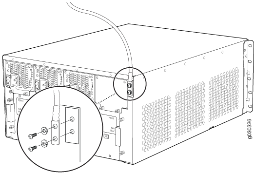
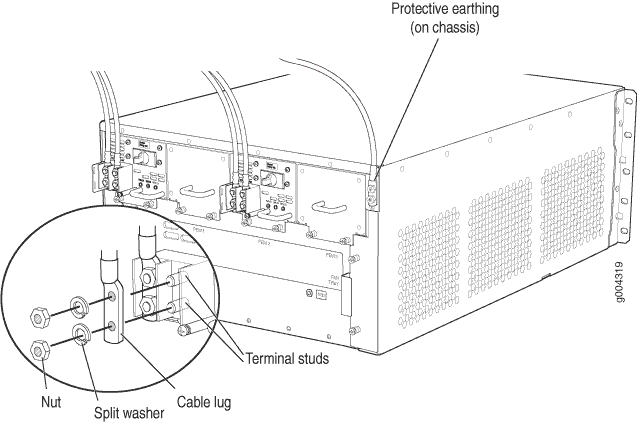
To meet safety and electromagnetic interference (EMI) requirements and to ensure proper operation, you must properly ground the firewall chassis before connecting power. You must install the SRX5400 in a restricted-access location and ensure that the chassis is always properly grounded. The SRX5400 has a two-hole protective grounding terminal provided on the chassis. See Figure 1. We recommend that you use this protective grounding terminal as the preferred method for grounding the chassis regardless of the power supply configuration. However, if additional grounding methods are available, you can also use those methods. For example, you can use the grounding wire in the AC power cord or use the grounding terminal or lug on a DC power supply. This tested system meets or exceeds all applicable EMC regulatory requirements with the two-hole protective grounding terminal.
You ground the device by connecting a grounding cable to earth ground and then attaching it to the chassis grounding points using UNC 1/4-20 two screws. You must provide the grounding cable (the cable lug is supplied with the device).
-
Secure the grounding cable lug to the grounding point, first with the washers,
and then with the screws as shown in Figure 1.
Figure 1: Connecting the Grounding Cable
Connecting Power to an AC-Powered SRX5400 Firewall
To meet safety and electromagnetic interference (EMI) requirements and to ensure proper operation, you must properly ground the firewall chassis before connecting power. See Grounding the SRX5400 Firewall for instructions.
Do not mix AC and DC power supplies within the same firewall. Damage to the device might occur.
The SRX5400 Firewall and SRX5600 Firewall use the same power supply model.
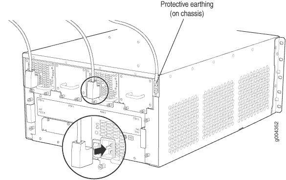
You connect AC power to the device by attaching power cords from the AC power sources to the AC appliance inlets located on the power supplies. The power cords are not provided with the firewall.
To connect the AC power cords to the device for each power supply (see Figure 2):
Powering On an AC-Powered SRX5400 Firewall
To power on an AC-powered firewall:
Connecting Power to a DC-Powered SRX5400 Firewall
Before you perform DC power procedures, ensure there is no power to the DC circuit. To ensure that all power is off, locate the circuit breaker on the panel board that services the DC circuit, switch the circuit breaker to the off position, and tape the switch handle of the circuit breaker in the off position.
To meet safety and electromagnetic interference (EMI) requirements and to ensure proper operation, you must properly ground the firewall chassis before connecting power. See Grounding the SRX5400 Firewall for instructions.
Do not mix AC and DC power supplies within the same firewall. Damage to the firewall might occur.
The SRX5400 Firewall and SRX5600 Firewall use the same power supply model.
You connect DC power to the firewall by attaching power cables from the external DC power sources to the terminal studs on the power supply faceplates. You must provide the power cables (the cable lugs are supplied with the device).
To connect the DC source power cables to the firewall:
-
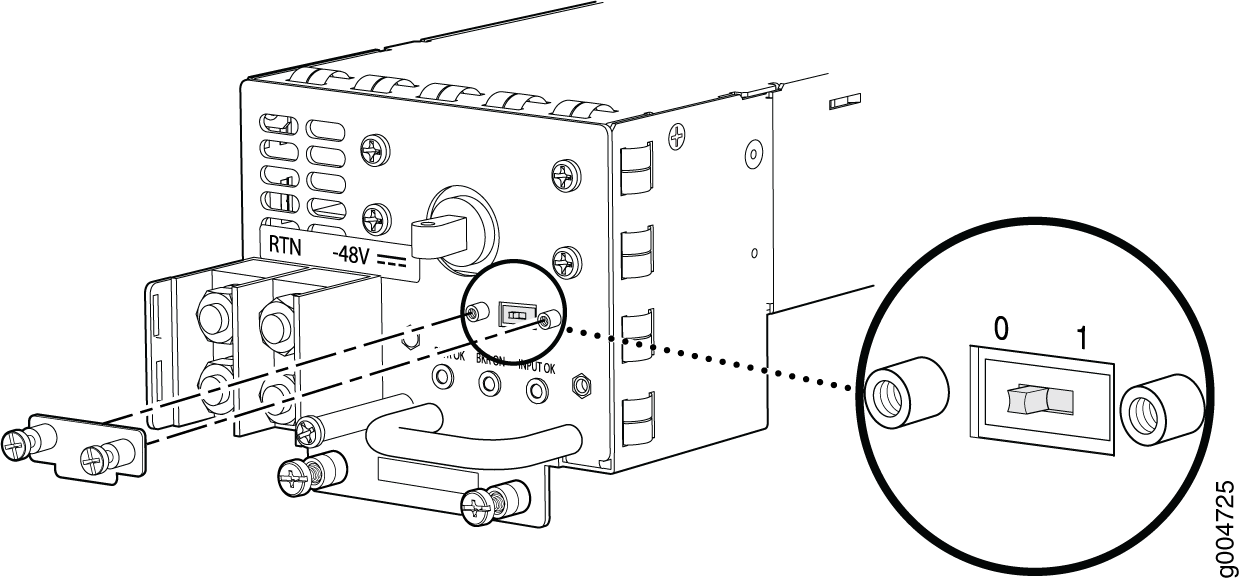
Check the setting of the input mode switch. Use a sharp, nonconductive object
to slide the switch to the desired position. Set the input mode switch to
position 0 for 60-A input and position 1 for 70-A input. This setting is used by
the power management software and must be set on the power supply. See Figure 3.
Figure 3: DC Power Supply Input Mode Switch
-
Install heat-shrink tubing insulation around the power cables.
To install heat-shrink tubing:
-
Slide the tubing over the portion of the cable where it is attached to the lug barrel. Ensure that tubing covers the end of the wire and the barrel of the lug attached to it.
-
Shrink the tubing with a heat gun. Ensure that you heat all sides of the tubing evenly so that it shrinks around the cable tightly.
Figure 4 shows the steps to install heat-shrink tubing.
Note:Do not overheat the tubing.
Figure 4: How to Install Heat-Shrink Tubing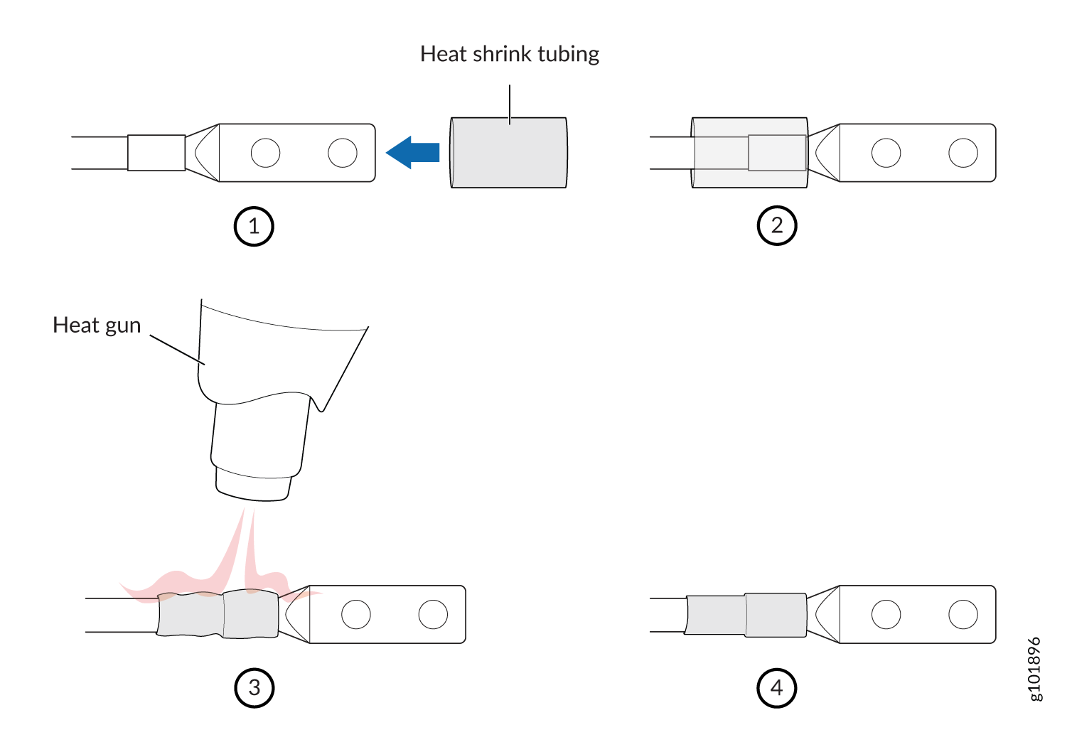
-
Powering On a DC-Powered SRX5400 Firewall
To power on a DC-powered firewall:
Powering Off the SRX5400 Firewall
After powering off a power supply, wait at least 60 seconds before turning it back on.
To power off the firewall: