Unpacking and Mounting the SRX4200
Unpacking the SRX4200 Services Gateway
The services gateway is shipped in a cardboard carton, secured with foam packing material. The carton also contains an accessory box and quick-start instructions.
The services gateway is maximally protected inside the cardboard carton. Do not unpack it until you are ready to begin installation.
To unpack the services gateway:
- Move the cardboard carton to a staging area as close to the installation site as possible, where you have enough room to remove the components from the chassis.
- Open the carton.
- Pull out the packing material holding the services gateway in place.
- Verify the parts received against the inventory (packing list). The packing list specifies the part numbers and carries a brief description of each part in your order.
- Save the shipping carton and packing materials in case you need to move or ship the services gateway at a later time.
Verifying Parts Received with the SRX4200 Services Gateway
A packing list is included in each shipment. Check the parts in the shipment against the items on the packing list. The packing list specifies the part numbers and descriptions of each part in your order.
If any part is missing, contact a customer service representative.
The parts shipped with your services gateway can vary depending on the configuration you ordered.
Table 1 lists the parts and their quantities in the packing list.
Component |
Quantity |
|---|---|
Services gateway |
1 |
Power supply (preinstalled) |
2 AC or DC |
AC power cord appropriate for your geographical location (only for AC models) |
2 |
Rack mount kit |
1 |
Documentation Roadmap and Product Warranty |
1 |
ROHS Card |
1 |
End User License Agreement |
1 |
Safety Guide |
1 |
DB-9 to RJ-45 cable |
1 |
RJ-45 cables |
2 |
Installing the SRX4200 Firewall in a Rack
You can mount the services gateway on four posts in a 19-in. rack or cabinet by using the rack-mount kit shipped with the device. (The remainder of this topic uses rack to mean rack or cabinet.)
Before mounting the device on four posts in a rack:
Verify that the site meets the requirements described in SRX4200 Site Preparation Checklist.
Place the rack or cabinet in its permanent location, allowing adequate clearance for airflow and maintenance, and secure it to the building structure.
Verify that the rack or cabinet meets the specific requirements described in SRX4200 Services Gateway Rack Requirements and Cabinet Requirements for SRX4200 Services Gateways.
Remove the services gateway from the shipping carton (see Unpacking the SRX4200 Services Gateway).
Ensure that you have the following parts and tools available:
Phillips (+) screwdriver, number 2
Fourteen flat-head screws (provided with the rack mount kit)
Eight rack-mounting screws to secure the chassis to the rack (not provided with the rack mount kit)
Installing the device in a rack requires two people: one person lifts the device while the other secures it to the rack.
If you are installing multiple devices in one rack, install the lowest one first and proceed upward in the rack.
To mount the services gateway in a four-post rack:
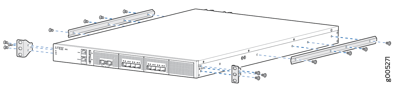
- Attach the mounting ears to the front of the chassis,
using the screws provided. Then, attach the fixed brackets to the
rear of the device, using the screws provided.Figure 1: Attaching the Mounting Ears and Fixed Brackets
 Note:
Note:Ensure that the rear of the device is supported throughout the process of mounting the device into the rack.
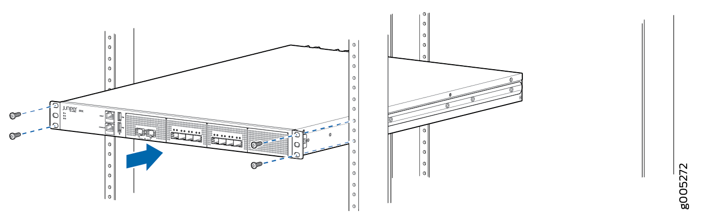
- Slide the device into the rack, and secure the mounting
ears to the rack, using the mounting screws.Figure 2: Securing the Mounting Ears to the Rack
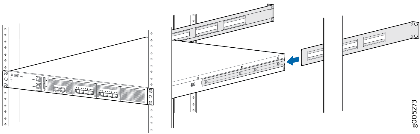
- Slide the adjustable brackets into the fixed brackets
attached to the rear of the device.Figure 3: Attaching the Adjustable Brackets
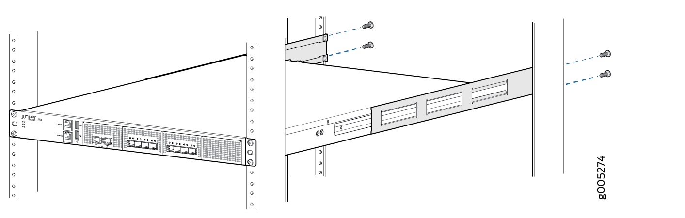
- Secure the adjustable brackets to the rack, using the
mounting screws.Figure 4: Securing the Adjustable Brackets to the Rack