Help us improve your experience.

Let us know what you think.

Do you have time for a two-minute survey?


Configuring Junos OS on the SRX320

The SRX320 Firewall is shipped with the Juniper Networks Junos operating system (Junos OS) preinstalled and is ready to be configured when the SRX320 is powered on. You can perform the initial software configuration of the SRX320 by using one of the following methods:

  • Command-line interface (CLI)

  • Zero touch provisioning (ZTP) with a cloud-based provisioning service

  • J-Web GUI

Before you configure your new SRX320, we recommend that you understand the factory-default configuration. In many cases you are able to leverage the factory defaults to simplify your configuration tasks. In other cases, you might find it easier to start with a blank configuration when you find that the defaults don't align with your planned usage. See SRX320 Firewall Factory-Default Settings for details on the factory-default configuration.

Initial Configuration Using the CLI

You can use either the serial or the mini-USB console port on the device.

Connect to the Serial Console Port

To connect to the serial console port:

  1. Plug one end of the Ethernet cable into the RJ-45 to DB-9 serial port adapter.
    Note:

    We no longer include a DB-9 to RJ-45 cable or a DB-9 to RJ-45 adapter with a CAT5E copper cable as part of the device package. If you require a console cable, you can order it separately with the part number JNP-CBL-RJ45-DB9 (DB-9 to RJ-45 adapter with a CAT5E copper cable).

  2. Plug the RJ-45 to DB-9 serial port adapter into the serial port on the management device.
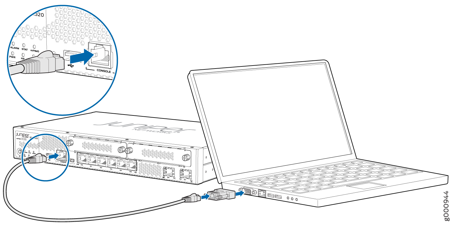
  3. Connect the other end of the Ethernet cable to the serial console port on the SRX320.
    Figure 1: Connect to the Console Port on the SRX320 Connect to the Console Port on the SRX320
  4. Start your asynchronous terminal emulation application (such as Microsoft Windows HyperTerminal) and select the appropriate COM port to use (for example, COM1).
  5. Configure the serial port settings with the following values:
    • Baud rate—9600

    • Parity—N

    • Data bits—8

    • Stop bits—1

    • Flow control—none

Connect to the Mini-USB Console Port

To connect to the mini-USB console port:

  1. Download the USB driver to the management device from the Downloads page. To download the driver for Windows OS, select 6.5 from the Version drop-down list. To download the driver for macOS, select 4.10 from the Version drop-down list.
  2. Install the USB console driver software:
    Note:

    Install the USB console driver software before attempting to establish a physical connection between the SRX320 and the management device, otherwise the connection will fail.

    1. Copy and extract the .zip file to your local folder.

    2. Double-click the .exe file. The installer screen appears.

    3. Click Install.

    4. Click Continue Anyway on the next screen to complete the installation.

      If you chose to stop the installation at any time during the process, then all or part of the software will fail to install. In such a case, we recommend that you uninstall the USB console driver and then reinstall it.

    5. Click OK when the installation is complete.

  3. Plug the large end of the USB cable supplied with the SRX320 into a USB port on the management device.
  4. Connect the other end of the USB cable to the mini-USB console port on the SRX320.
  5. Start your asynchronous terminal emulation application (such as Microsoft Windows HyperTerminal) and select the new COM port installed by the USB console driver software. In most cases, this is the highest-numbered COM port in the selection menu.

    You can locate the COM port under Ports (COM & LPT) in Windows Device Manager after the driver is installed and initialized. This might take several seconds.

  6. Configure the port settings with the following values:
    • Bits per second—9600

    • Parity—None

    • Data bits—8

    • Stop bits—1

    • Flow control—None

  7. If you have not already done so, power on the SRX320 by pressing the Power button on the front panel. Verify that the PWR LED on the front panel turns green.

    The terminal emulation screen on your management device displays the startup sequence. When the SRX320 has finished starting up, a login prompt appears.

Configure the SRX320 Using the CLI

This section assumes you are performing initial configuration of a new SRX320 running a factory default configuration. We show you how to leverage the defaults to quickly get the SRX320 on the internet and able to be managed locally or remotely. See SRX320 Firewall Factory-Default Settings for details on the SRX320 factory defaults.

For this section, however, we assume the service provider does not support DHCP address assignment on the WAN interface. This allows us to show you how to configure an interface and static route using the Junos CLI.

To perform initial configuration on the SRX320 using the CLI:

  1. Login as the root user and start the CLI. No password is needed when running the factory default.
    Note:

    You can view the current configuration, whether factory-default or not, by using the show configuration operational mode command.

  2. Enter configuration mode.
  3. Remove the ZTP configuration and set the root user authentication.

    The ZTP configuration is not needed when performing the initial configuration using the CLI. Removing the ZTP configuration stops the periodic log messages that report the ZTP status on the console.

    Set the root authentication password using a cleartext value. You cannot commit the change that deactivates ZTP unless you also set the root password.

  4. Commit the configuration to activate the changes that removed ZTP and configured the root password.
  5. Configure the management interface. Given the factory default settings, we recommend using the ge-0/0/0 interface for remote management of the SRX320 over the WAN network. You can also locally manage the SRX320 using one of the LAN ports (ge-0/0/1 through ge-0/0/6).

    If the WAN service provider supports DHCP IP address assignment you skip this step and let the factory default settings work for you. In this example, the Internet provider requires a static IP address configuration. You must remove the default DHCP client setting in order to configure the IP address manually.

  6. If the WAN service provider supports DHCP assignment of a default route you skip this step and let the factory default settings work for you. In this example, the Internet provider does not support DHCP. Therefore, you configure a static default route to provide the management interface. This route is used to reach remote destinations, such as a cloud provisioning service or the remote management station.
  7. Enable the SSH protocol for remote access. By default, the root user cannot login remotely. You also enable root login over SSH in this step.
  8. Enable SSH host support for the ge-0/0/0 interface. Recall that in the default configuration the ge-0/0/0 interface is in the untrust zone, and that the untrust zone does not support host bound SSH.
  9. Configure the hostname.
  10. (Optional) Configure domain name resolution, the time zone, and an NTP-based clock source.
  11. That's it! The initial configuration is complete. Commit the configuration to activate the changes on the SRX320.

    The resulting connectivity is shown below.

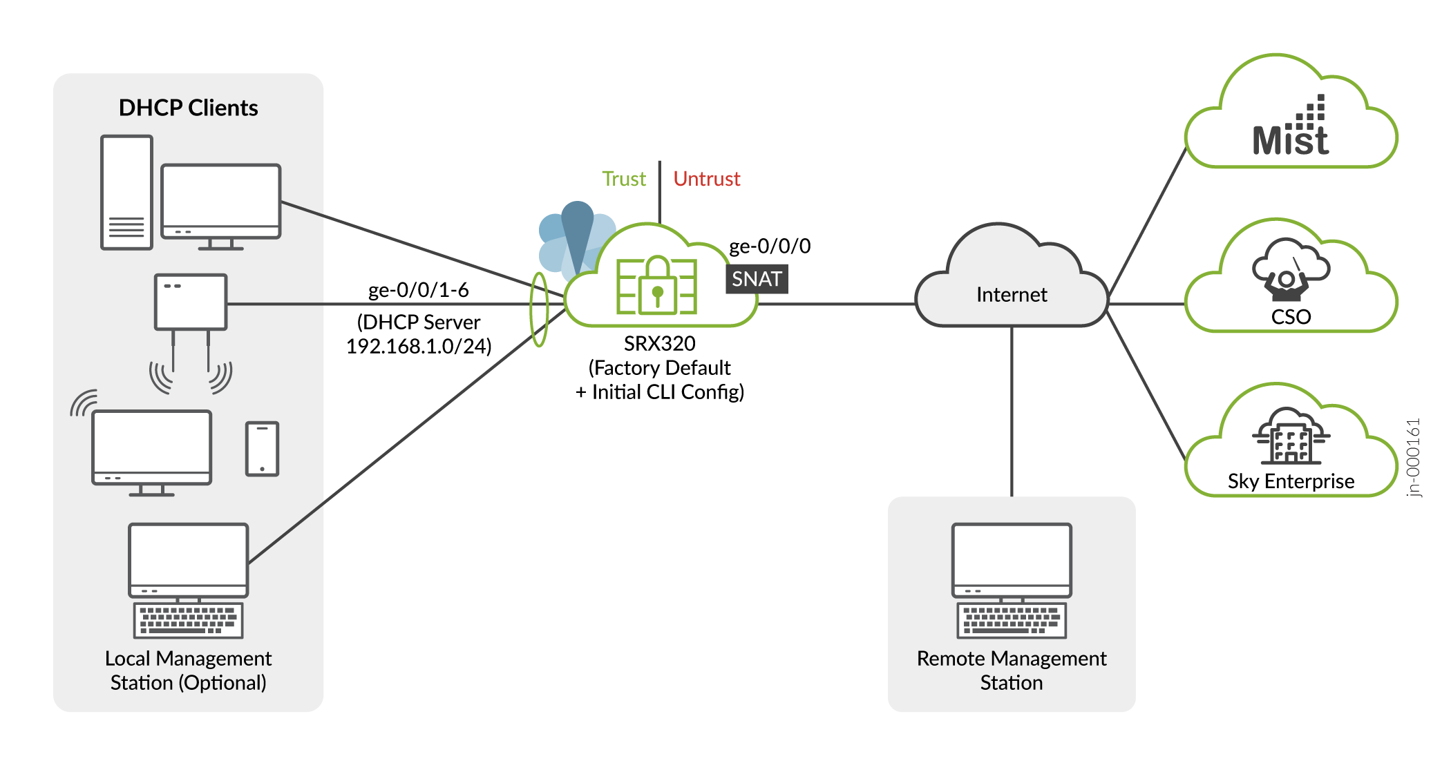
    A few things to keep in mind about your new SRX320 branch network:

    • You access the SRX CLI or J-Web user interface locally using the 192.168.1.1 address. To access the SRX remotely, specify the IP address assigned by the WAN provider. Simply issue a show interfaces ge-0/0/0 terse CLI command to confirm the address in use by the WAN interface.

    • Devices attached to the LAN ports are configured to use DHCP. They receive their network configuration from the SRX. These devices obtain an IP address from the 192.168.1.0/24 address pool and use the SRX as their default gateway.

    • All LAN ports are in the same subnet with Layer 2 connectivity. All traffic is permitted between all trust zone interfaces.

    • All traffic originating in the trust zone is permitted in the untrust zone. Matching response traffic is allowed back from the untrust to the trust zone. Traffic that originates from the untrust zone is blocked from the trust zone.

    •The SRX performs source NAT (S-NAT) using the WAN interface’s IP for traffic sent to the WAN that originated from the trust zone.

    •Traffic associated with specific system services (HTTPS, DHCP, TFTP, and SSH) is permitted from the untrust zone to the local host. All local host services and protocols are allowed for traffic that originates from the trust zone.

Configure the SRX320 Using J-Web

Perform Initial Configuration Using J-Web

The J-Web user interface supports a setup wizard, which you can use to perform the initial configuration of the device.

  1. Connect one end of the Ethernet cable to any of the network ports numbered 0/1 through 0/6 on the device.
    Note:

    The ge-0/0/0 and ge-0/0/7 interfaces (ports 0/0 and 0/7) are WAN interfaces. Don't use these ports for the initial configuration procedure.

  2. Connect the other end of the Ethernet cable to the management device.
    Figure 2: Connect the SRX320 to a Management Device Connect the SRX320 to a Management Device

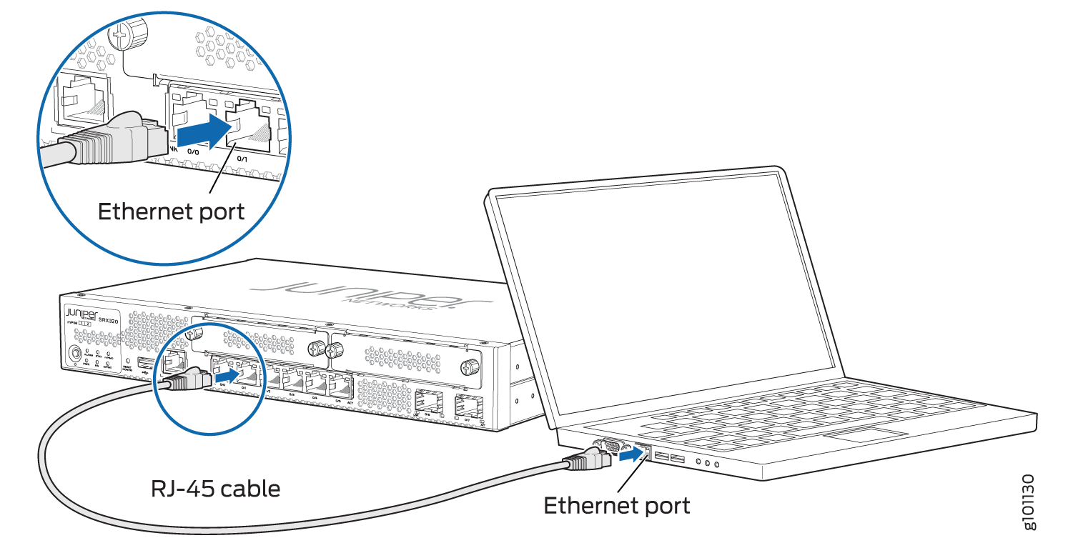
    The SRX320 functions as a DHCP server and automatically assigns an IP address to the laptop.

  3. Ensure that the management device acquires an IP address on the 192.168.1.0/24 network from the device.

    If an IP address is not assigned to the management device, manually configure an IP address in the 192.168.1.0/24 network.

    Note:

    Don't assign the 192.168.1.1 IP address to the management device, as this IP address is assigned to the SRX320.

  4. Open a browser and enter https://192.168.1.1 as the target URL. The J-Web screen appears. For information on accessing the J-Web interface, see Access the J-Web Interface. For information on using J-Web to perform initial configuration, see The J-Web Setup Wizard.

Manage the SRX320 Using J-Web

After initial device configuration is complete you can use J-Web to perform ongoing configuration, management, and health monitoring of your SRX320 device.

For more information, see the SRX J-Web documentation for your release at https://www.juniper.net/documentation/product/us/en/j-web-srx-series.

Configure the Device Using ZTP with Juniper Networks Network Service Controller

Note:

You can configure using ZTP for Junos OS Release 19.2 and earlier releases.

You can use ZTP to complete the initial configuration of the SRX320 in your network automatically, with minimum intervention.

Network Service Controller is a component of the Juniper Networks Contrail Service Orchestration platform that simplifies and automates the design and implementation of custom network services that use an open framework.

For more information, refer to the Network Service Controller section in the datasheet at http://www.juniper.net/assets/us/en/local/pdf/datasheets/1000559-en.pdf.

To configure the device automatically using ZTP:

Note:

To complete the ZTP process, ensure that the SRX320 is connected to the Internet.

  • If you already have the authentication code, enter the code in the webpage displayed.

    Figure 3: Authentication Code PageAuthentication Code Page

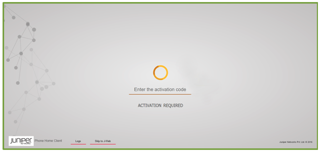
    On successful authentication, the initial configuration is applied and committed on the SRX320. Optionally, the latest Junos OS image is installed on the SRX320 before the initial configuration is applied.

  • If you do not have the authentication code, you can use the J-Web setup wizard to configure the SRX320. Click Skip to J-Web and configure the SRX320 using J-Web.