SRX1500 Site Guidelines and Requirements
SRX1500 Firewall General Site Installation Guidelines
The following precautions help you plan an acceptable operating environment for your SRX1500 Firewall and avoid environmentally caused equipment failures:
For the cooling system to function properly, the airflow around the chassis must be unrestricted. Allow sufficient clearance between the front and back of the chassis and adjacent equipment. Ensure that there is adequate circulation in the installation location.
Follow the ESD procedures to avoid damaging equipment. Static discharge can cause components to fail completely or intermittently over time. For more information, see Prevention of Electrostatic Discharge Damage.
Ensure that the blank panels are installed into empty slots to prevent any interruption or reduction in the flow of air across internal components.
Install the services gateway only in restricted areas, such as dedicated equipment rooms and equipment closets, in accordance with Articles 110–16, 110–17, and 110–18 of the National Electrical Code, ANSI/NFPA 70.
SRX1500 Firewall Environmental Specifications
Table 1 provides the required environmental conditions for normal SRX1500 Firewall operations. In addition, the site must be as dust-free as possible because dust can clog air intake vents, reducing the efficiency of the cooling system.
Description |
Value |
|---|---|
Altitude |
No performance degradation to 10,000 ft (3048 m) |
Relative humidity |
Normal operation ensured in relative humidity range of 5% to 90%, noncondensing |
Temperature |
|
Maximum thermal output |
614 BTU/hour |
Average heat dissipation |
512 BTU / hour |
Noise level |
66.5 dBA |
SRX1500 Firewall Electrical Wiring Guidelines
Table 2 describes the factors you must consider while planning the electrical wiring for the SRX1500 Firewall at your site.
It is particularly important to provide a properly grounded and shielded environment and to use electrical surge-suppression devices.
Site Wiring Factor |
Guideline |
|---|---|
Signaling limitations |
To ensure that signaling functions optimally:
|
Radio frequency interference (RFI) |
To reduce or eliminate the emission of RFI from your site wiring:
|
Electromagnetic compatibility (EMC) |
Provide a properly grounded and shielded environment and use electrical surge-suppression devices. Strong sources of electromagnetic interference (EMI) can cause the following damage:
Tip:
If your site is susceptible to problems with EMC, particularly from lightning or radio transmitters, you might want to seek expert advice. |
Some ports are designed for use as intrabuilding interfaces only Type 2 or Type 4 ports, the battery return connection is to be treated as an Isolated DC return (that is, DC-I), as defined in GR-1089-CORE and require isolation from the exposed OSP cabling. To comply with NEBS requirements and protect against lightning surges and commercial power disturbances, the intrabuilding port(s) of the device MUST NOT be metallically connected to interfaces that connect to the OSP or its wiring. The intrabuilding port(s) of the device is suitable for connection to intrabuilding or unexposed wiring or cabling only. The addition of primary protectors is not sufficient protection to connect these interfaces metallically to OSP wiring.
SRX1500 Firewall Grounding Specifications
To meet safety and electromagnetic interference (EMI) requirements and to ensure proper operation, the SRX1500 Firewall must be adequately grounded before power is connected. You must provide a grounding lug to connect the services gateway to earth ground.
Before you connect power to the services gateway, a licensed electrician must attach a cable lug to the grounding and power cables that you supply. A cable with an incorrectly attached lug can damage the services gateway (for example, by causing a short circuit).
The services gateway chassis has one grounding point on the back panel. The grounding point consists of two threaded holes spaced 0.625 in. (15.86 mm) apart.
Table 3 lists the specifications of the grounding cable used with the device.
You must install the SRX1500 in a restricted-access location and ensure that the chassis is always properly grounded. The SRX1500 has a two-hole protective grounding terminal provided on the chassis. Under all circumstances, use this grounding connection to ground the chassis. For AC-powered systems, you must also use the grounding wire in the AC power cord along with the two-hole grounding lug connection. This tested system meets or exceeds all applicable EMC regulatory requirements with the two-hole protective grounding terminal.
|
Grounding Requirement |
Specification |
|---|---|
|
Grounding cable |
14 AWG single-strand wire cable |
|
Amperage of grounding cable |
Up to 25A |
See Also
SRX1500 Firewall Physical Specifications
Table 4 lists the physical specifications for the services gateway.
|
Physical Specification of Chassis |
Value |
|---|---|
|
Height |
1.75 in. |
|
Width |
17.28 in. |
|
Depth |
18.2 in. |
|
Weight |
15 lb. |
See Also
SRX1500 Firewall Clearance Requirements for Airflow and Hardware Maintenance
When planning the installation site for the SRX1500 Firewall, you need to allow sufficient clearance around the rack. Consider the following:
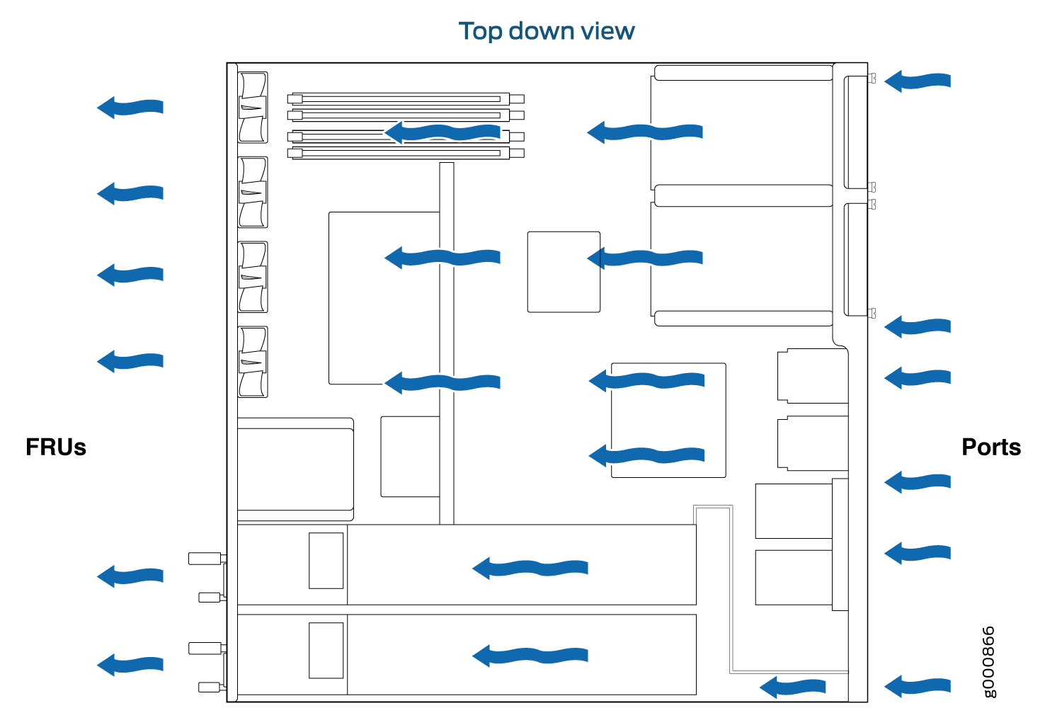
For the cooling system to function properly, the airflow around the chassis must be unrestricted. The fan tray contains four fans and provides front-to-back chassis cooling. Figure 1 shows the direction of airflow through the chassis.
For service personnel to remove and install hardware components, there must be adequate space at the front and back of the services gateway as indicated in Table 5.
If you are mounting the services gateway in a rack with other equipment, ensure that the exhaust from other equipment does not blow into the intake vents of the chassis.
Table 5 provides information about the clearance requirements for maintaining optimum airflow and the distances necessary to facilitate easy maintenance of the services gateway.
Location |
Recommended Clearance |
Requirement for Clearance |
|---|---|---|
Front of the chassis |
8.7 in. (22 cm) |
Space for service personnel to remove and install hardware components |
Rear of the chassis |
17.4 in. (44.2 cm) |
Space for service personnel to remove and install hardware components |
Between front-mounting flange and rack or cabinet edge |
2.5 in. (6.35 cm) |
Space for cable management and organization |
Between both sides of the chassis and any non-heat-producing surface such as a wall or cabinet side |
6.0 in. (15.24 cm) |
Space for the cooling system to function properly and to maintain unrestricted airflow around the chassis |
Figure 1 shows the airflow through the chassis.
Rack Requirements
When installing the services gateway in a rack, you must ensure that the rack complies with a 1U (19 in. or 48.7 cm) rack as defined in Cabinets, Racks, Panels, and Associated Equipment (document number EIA-310-D), published by the Electronic Industries Alliance (http://www.ecaus.org/eia/site/index.html).
When selecting a rack, ensure that the physical characteristics of the rack comply with the following specifications:
The outer edges of the mounting brackets extend the width of either chassis to 19 in. (48.3 cm).
The front of the chassis extends approximately 0.5 in. (1.27 cm) beyond the mounting ears.
Maximum permissible ambient temperature when two devices are placed side by side in a 19 in. rack is 40° C.
The spacing of the mounting brackets and flange holes on the rack and device mounting brackets are as follows:
The holes within each rack set are spaced at 1 U (1.75 in. or 4.5 cm).
The mounting brackets and front-mount flanges used to attach the chassis to a rack are designed to fasten to holes spaced at rack distances of 1 U (1.75 in.).
The mounting holes in the mounting brackets provided with the device are spaced 1.25 in. (3.2 cm) apart (top and bottom mounting hole).
Always secure the rack in which you are installing the services gateway to the structure of the building. If your geographical area is subject to earthquakes, bolt the rack to the floor. For maximum stability, also secure the rack to ceiling brackets.
Cabinet Requirements
You can install the services gateway in a 19 in. (48.7 cm) cabinet as defined in Cabinets, Racks, Panels, and Associated Equipment (document number EIA-310-D) published by the Electronic Industries Alliance (http://www.ecaus.org/eia/site/index.html). You must mount the services gateway horizontally in the cabinet using appropriate rack adapters.
When selecting a cabinet, ensure that it meets the following specifications:
The cabinet is at least 1U (3.50 in. or 8.89 cm) and can accommodate the services gateway.
The outer edges of the mounting brackets extend the width of either chassis to 19 in. (48.7 cm), and the front of the chassis extends approximately 0.5 in. (1.27 cm) beyond the mounting brackets.
The minimum total clearance inside the cabinet is 30.7 in. (78 cm) between the inside of the front door and the inside of the rear door.
A cabinet larger than the minimum required provides better airflow and reduces the chance of overheating.
When you mount the services gateway in a cabinet, you must ensure that ventilation through the cabinet is sufficient to prevent overheating. Consider the following when planning for chassis cooling:
Ensure that the cool air supply you provide through the cabinet can adequately dissipate the thermal output of the services gateway.
Install the services gateway as close as possible to the front of the cabinet so that the cable management system clears the inside of the front door. Installing the chassis close to the front of the cabinet maximizes the clearance in the rear of the cabinet for critical airflow.
Route and dress all cables to minimize the blockage of airflow to and from the chassis.