SRX1500 Chassis
SRX1500 Firewall Chassis Overview
The SRX1500 Firewall chassis is a rigid sheet metal structure that houses all the other hardware components. The chassis weighs 15 lb. and measures 1.75 in. high, 17.5 in. wide, and 18.2 in. deep. The chassis installs in standard 600-mm deep (or larger) enclosed cabinets or 19-in. equipment racks.
Before removing or installing components of a functioning services gateway, attach an electrostatic discharge (ESD) strap to an ESD point and place the other end of the strap around your bare wrist. Failure to use an ESD strap could result in damage to the device.
The services gateway must be connected to earth ground during normal operation. The protective earthing terminal on the rear of the chassis is provided to connect the services gateway to ground. Additional grounding is provided to an AC-powered services gateway when you plug its power supply into a grounded AC power receptacle.
SRX1500 Firewall Front Panel
Figure 1 shows the front panel of the SRX1500 Firewall. The front panel contains LEDs, Power and Reset Config buttons, and various ports.
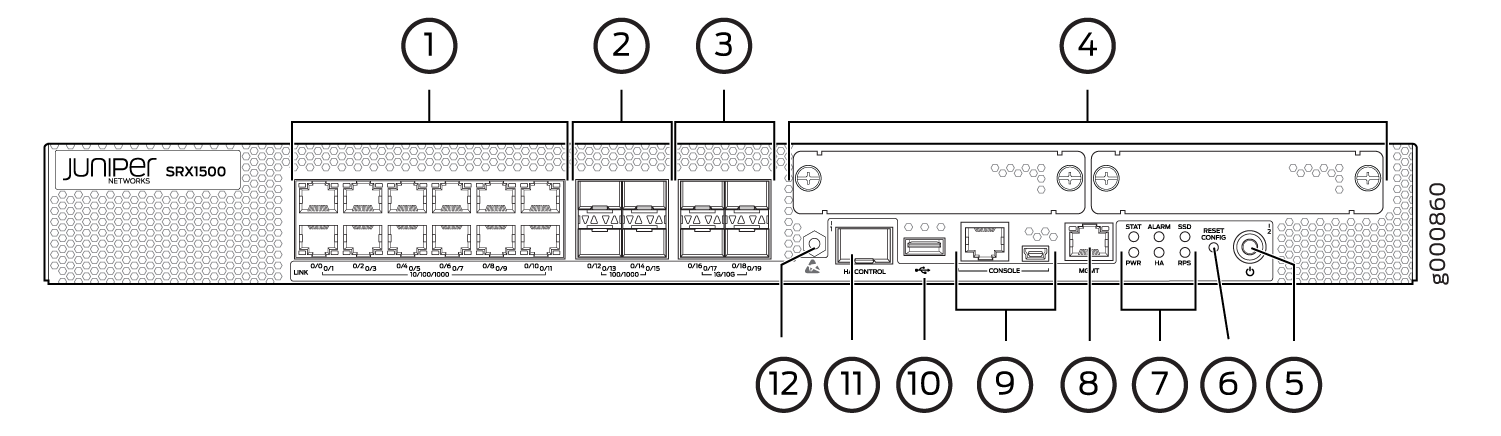
Table 1 provides information about the front panel components of the services gateway.
Callout |
Component |
Description |
|---|---|---|
1 |
10/100/1000 Base-T ports |
Twelve 10/100/1000 Base-T ports.Top: 0/0, 0/2, 0/4, 0/6, 0/8, and 0/10Bottom: 0/1, 0/3, 0/5, 0/7, 0/9, and 0/11 The ports have the following characteristics:
The ports can be used to:
|
2 |
100/1000 SFP ports |
Four 1-Gigabit Ethernet small form-factor pluggable (SFP) ports for network trafficTop: 0/12 and 0/14Bottom: 0/13 and 0/15 |
3 |
1G/10G SFP+ ports |
Four 1-Gigabit Ethernet/10-Gigabit Ethernet enhanced small form-factor pluggable (SFP+) ports for network trafficTop: 0/16 and 0/18Bottom: 0/17 and 0/19 |
4 |
WAN PIM slots |
Two WAN PIM slots. WAN PIMs are used to add WAN interfaces to the services gateway. Note:
The WAN PIMs are currently not available for ordering. |
5 |
Power button |
Use the Power button to shut down the services gateway. On a services gateway that has been previously shut down using the Power button, when the power button is pressed again the services gateway starts up. |
6 |
Reset config button |
Returns the services gateway to the factory-default configuration. |
7 |
LEDs |
Indicate component and system status and troubleshooting information at a glance. See Table 2. |
8 |
Management port |
Use the management (MGMT) port to connect to the device over the network. |
9 |
Console port |
|
10 |
USB port |
The services gateway has one USB port that accepts a USB storage device. |
11 |
HA control port |
Dedicated Gigabit Ethernet SFP port to synchronize data and maintain state information in a chassis cluster setup. |
12 |
ESD point |
For personal safety, while working on the services gateway, use the ESD outlet to plug in an ESD grounding strap to prevent your body from sending static charges to the services gateway. |
For information on supported transceivers, see the Hardware Compatibility Tool.
Figure 2 shows the SRX1500 Firewall LEDs.
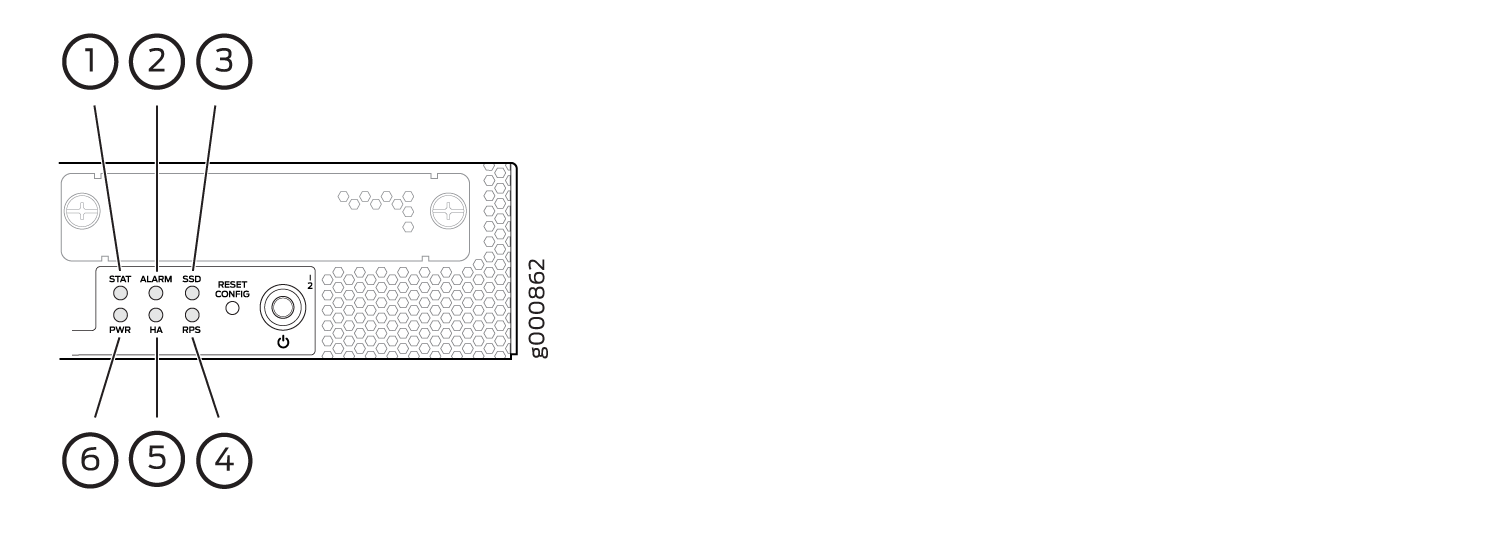
Table 2 lists the SRX1500 Firewall LEDs.
Callout |
LED |
Description |
|---|---|---|
1 |
STAT |
|
2 |
ALARM |
|
3 |
SSD |
|
4 |
RPS |
|
5 |
HA |
|
6 |
PWR |
|
Management Port LEDs
The management port has two LEDs that indicate link activity and status of the management port.
Table 3 describes the LEDs.
LED |
Description |
|---|---|
Link (LED on the left) |
|
Activity (LED on the right) |
|
Network Port LEDs
The SFP and Ethernet ports have two status LEDs, LINK and ACT, located above the port.
LED |
Description |
|---|---|
LINK (LED on the left) |
|
ACT (LED on the right) |
|
HA Port LEDs
The HA port has two LEDs located above the port to indicate status.
LED |
Description |
|---|---|
Link (LED on the left) |
|
Activity (LED on the right) |
|
SRX1500 Firewall Back Panel
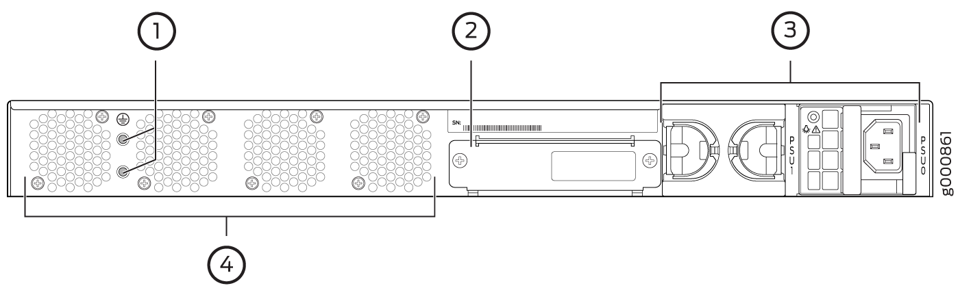
Figure 3 shows the back panel of the SRX1500 Firewall and Table 6 lists the back panel components.
Callout |
Component |
Description |
|---|---|---|
1 |
Grounding point |
Connects the services gateway chassis to earth ground. |
2 |
SSD slot |
Contains the SSD storage device. |
3 |
Power supply |
Two power supply slots. Each power supply contains a power cord outlet. One 400 W AC or 650 W DC power supply is provided with the services gateway. |
4 |
Fans |
Four fans for cooling the services gateway and its components. |