Fast Track to Rack Installation and Power
This procedure guides you through the simplest steps to install your QFX5250 Switch in a rack and connect it to power. Have more complex installation needs? See Install the QFX5250 Switch.

The QFX5250-64OE-L, a liquid-cooled model of the Juniper Networks® QFX5250 switch, is designed for installation on an ORv3 rack.
Follow these steps to install the QFX5250 switch.
Install QFX5250 Liquid-Cooled Switch (2OU) in ORv3 Rack
Before you install the switch in an ORv3 rack, make sure you complete the following steps:
-
Check that your site meets all the requirements listed in the switch’s site preparation checklist.
-
Place the rack in its final spot and leave enough space around it for maintenance.
-
Secure the rack to the building structure.
-
For the liquid-cooling system, ensure that the following are in place before installing the switch:
-
The Cooling Distribution Unit (CDU) or centralized cooling system should be connected and working.
-
The inlet and outlet UQDB06 sockets on the ORv3 rack manifolds and the inlet and outlet UQDB06 plugs on QFX5250 must be uncapped.
Note: On successful installation, the UQDB06 inlet and outlet plugs on the QFX5250 switch blind-mates with the corresponding UQDB06 sockets on the ORv3 rack inlet and outlet manifolds. -
Maintain the recommended flow rate specifications. See Table 1.
-
On first installation, verify that the nitrogen in the coolant lines is automatically bled when the system powers on.
-
-
Read General Safety Guidelines and Warnings, with particular attention to Chassis and Component Lifting Guidelines.
To install the switch in an ORv3 rack:
-
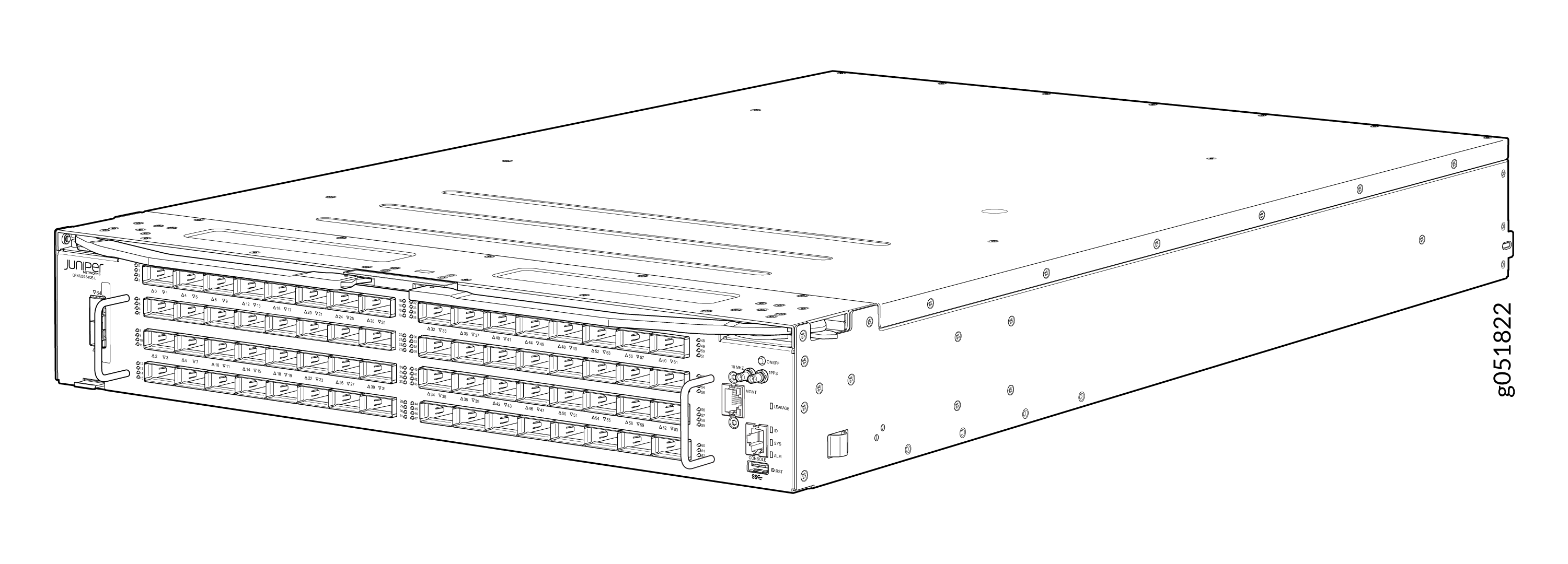
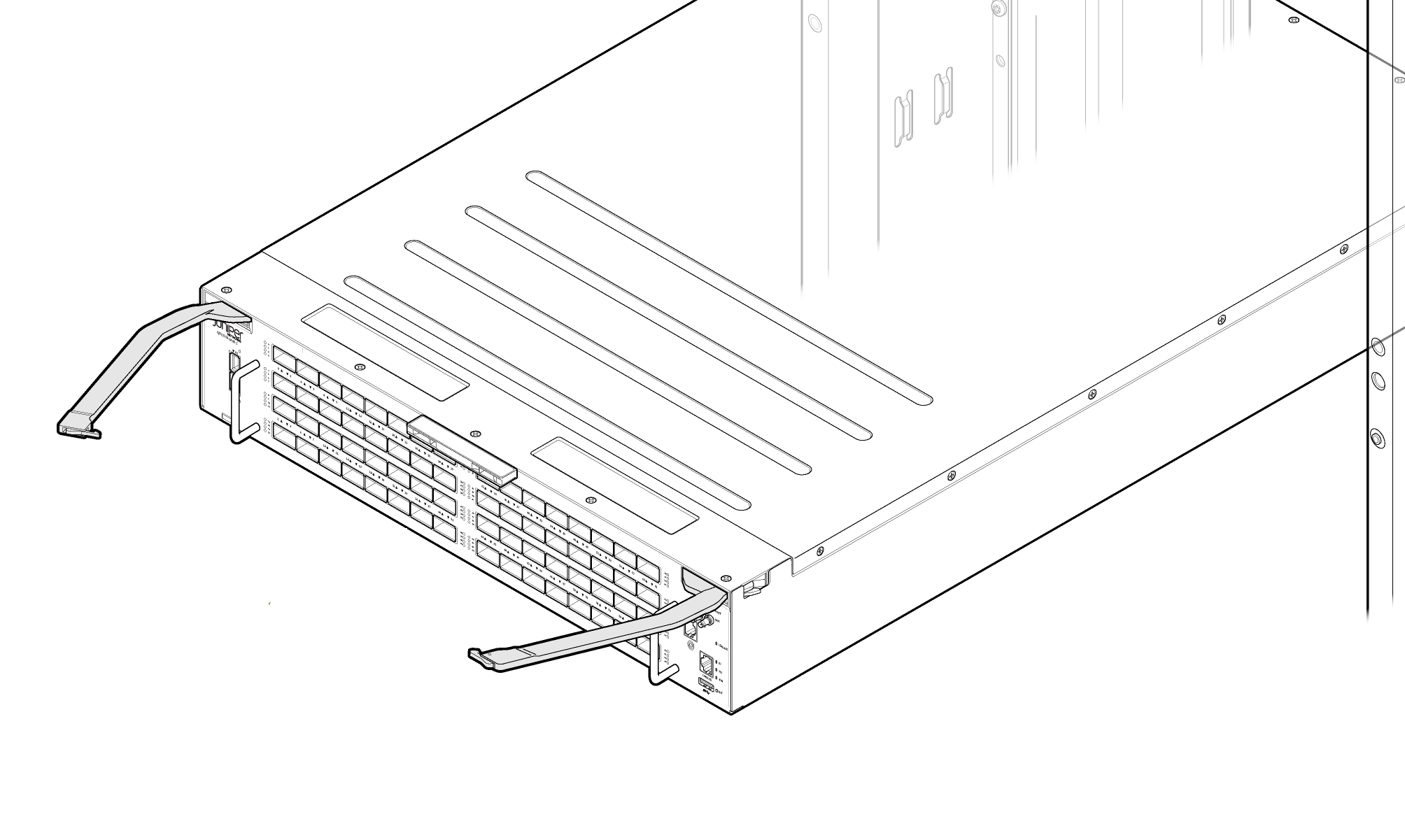
Remove the switch from shipping carton. See Figure 1.
Figure 1: QFX5250-64OE-L Switch
-
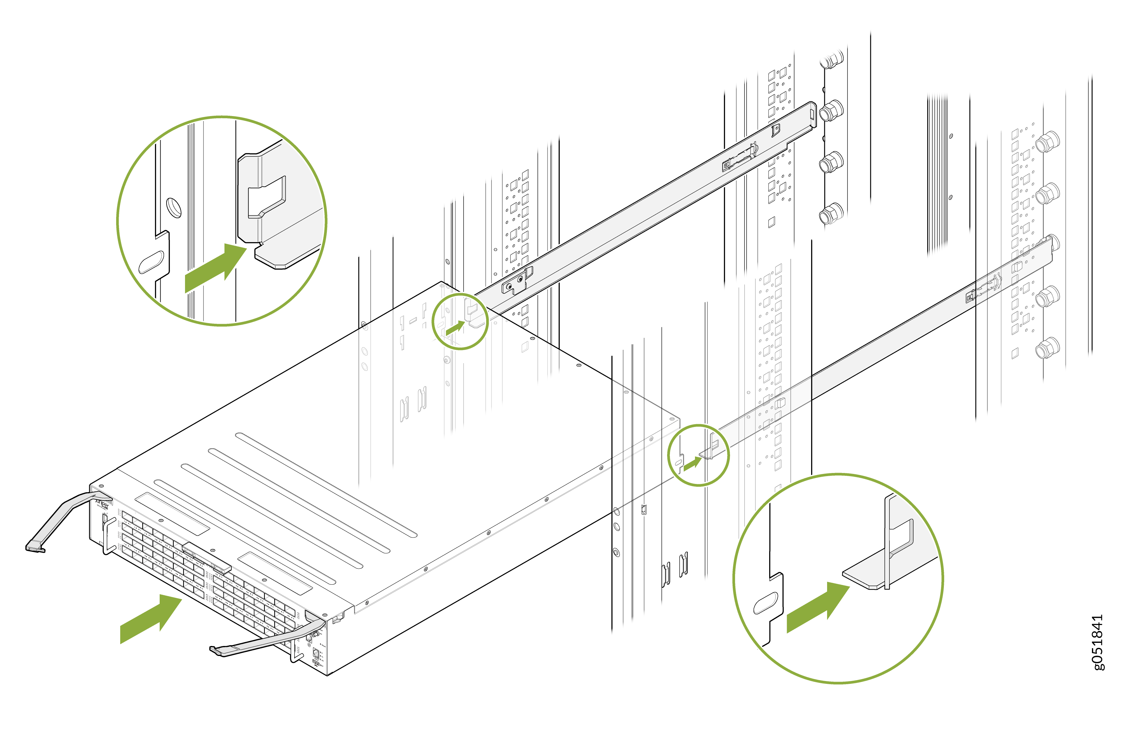
Align the rails and secure the rails in place on your ORv3 rack. See Figure 2
Figure 2: Align the Rails in ORv3 Rack
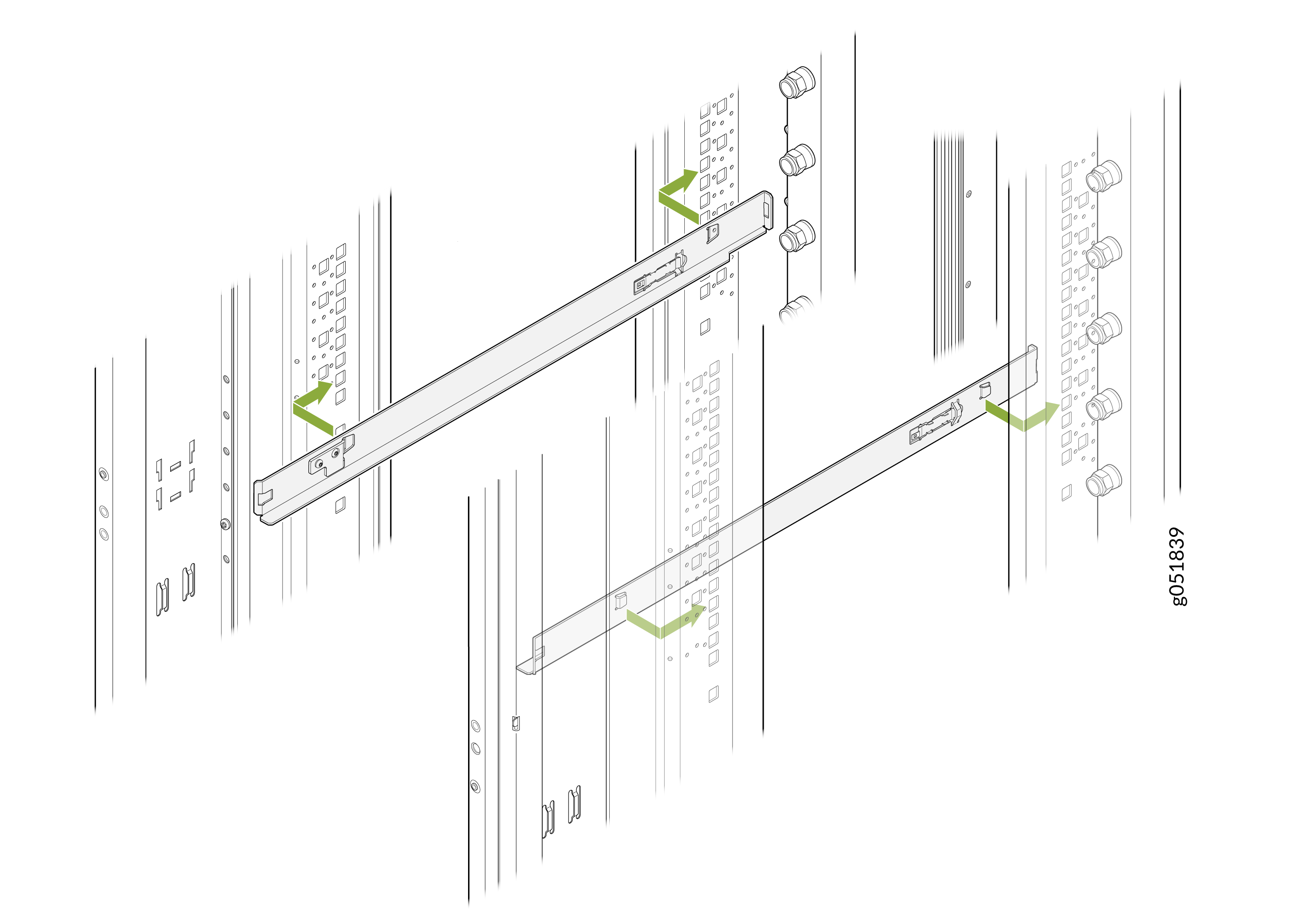 Note: Rails are not provided with the switch.Note:
You must use 1OU standard rails to install the 2OU QFX5250 liquid-cooled switches on ORv3 racks.
-
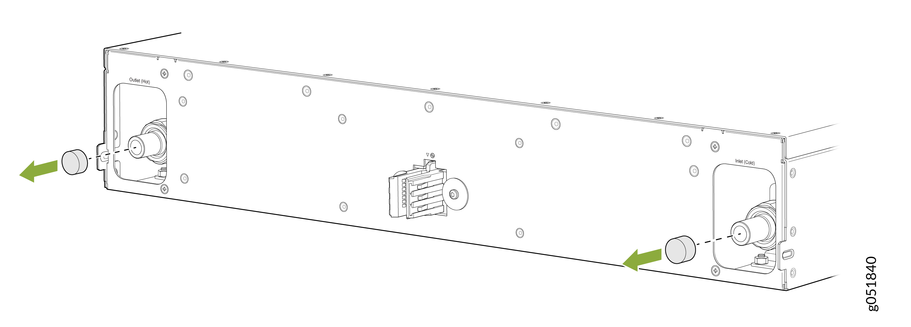
Remove the caps on the UQDB06 plugs on the switch for coolant inlet and
outlet from the ORv3 rack manifolds.
Figure 3: Remove the Caps on the Liquid Inlet and Outlet UQDB06 Plugs
-
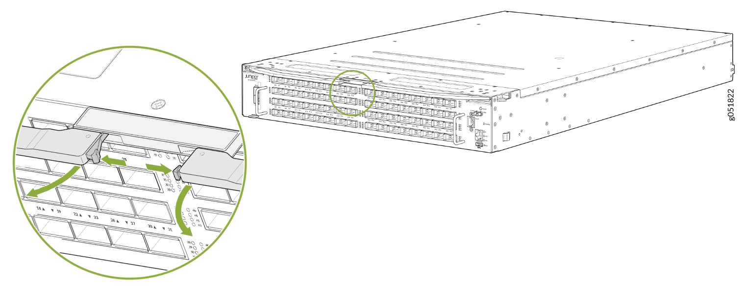
Press the push button on both ejector levers to release the ejector lock.
Note: Ensure that both ejector levers are opened together.Figure 4: Press the Push Button
-
Pull the ejector levers outward to the open position.
Figure 5: Switch Ejector Levers in Open Position
-
Carefully align the switch with the rails in the rack and slide the switch
into the rack. See Figure 6.
Figure 6: Slide the Switch into the Rack
-
Close the ejector levers inward and lock them on the front panel of the
switch. The IT Gear Input Connector at the rear of the switch fully engages
with the busbar.
Note: Ensure that both ejector levers are closed together.Note:
The internal coolant lines or tubes of the QFX5250 switch are shipped pre-filled with nitrogen. The nitrogen bleeds during the first rack installation. When liquid coolant enters the switch through the inlet UQDB06 plug and socket, the nitrogen in the tubing is displaced by the coolant. The displaced nitrogen is removed through the outlet UQDB06 plug of the switch.
Figure 7: Close the Ejector Levers on the Fully Inserted Switch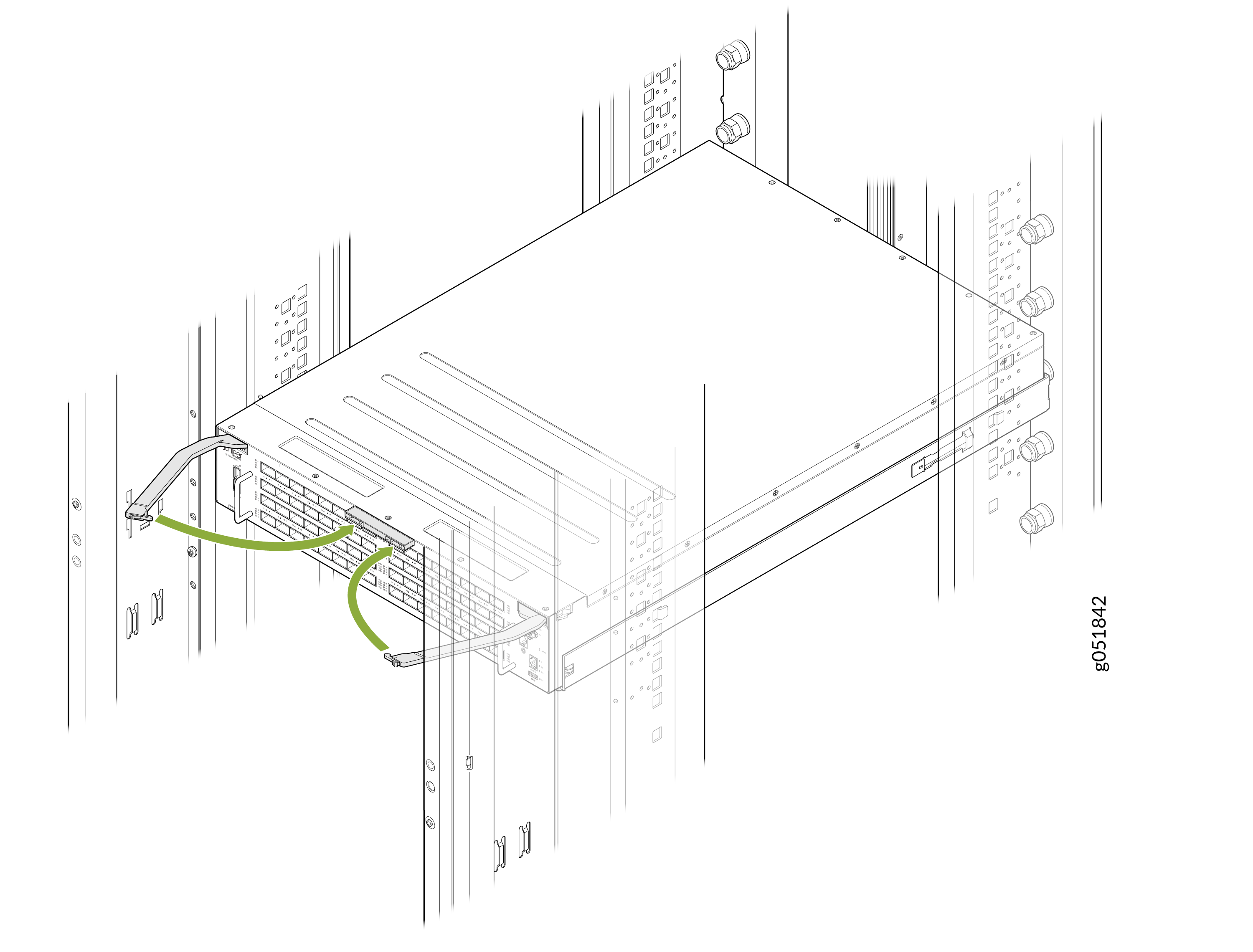 Note:
Note:For the switch installed in an ORv3 rack, you do not require an additional grounding or power configuration. The ORv3 rack infrastructure provides integrated power delivery and grounding.
Note:The busbar on the ORv3 rack supplies power to the switch. The standard ORv3 rack used with the QFX5250 has an output voltage of 46 V DC to 56 V DC.
Connect to Power
For the QFX5250 Switch installed in an ORv3 rack, you do not require an additional grounding or power configuration. The ORv3 rack infrastructure provides integrated power delivery and grounding. Ensure you install and ground the rack properly according to site standards.
Ground the ORv3-Compliant QFX5250 Switches
The grounding information provided in this section is valid for the following model of QFX5250:
-
QFX5250-64OE-L—Grounding is already provided to the switch that is installed on the ORv3 rack.
Note:The ORv3 connector provides integrated grounding and no additional grounding is required. The switch is connected to earth ground when you slide the switch into the ORv3 rack.
Connect the ORv3 Compliant QFX5250 Switch to Power
The powering-on information provided in this section is valid for the following model of QFX5250:
-
QFX5250-64OE-L—Power is provided to the switch installed on the ORv3 rack through the busbar. For more information on grounding and powering on the liquid-cooled QFX5250 model installed on an ORv3 rack, see How to Install QFX5250 Liquid-cooled Switch (2OU) in ORv3 Rack.
For the switch installed in an ORv3 rack, you do not require any additional power configuration. The ORv3 rack infrastructure provides integrated power delivery. The busbar on the ORv3 rack delivers power to the QFX5250 Switch.
When you slide the switch into the ORv3 rack unit, the IT Gear Input Connector at the rear of the switch engages with the busbar on the ORv3 rack to power on the switch.
Sliding the switch out of the ORv3 rack disconnects the power supply.