Fast Track to Rack Installation and Powering Connection
This procedure walks you through the basic steps for installing your QFX5241-32OD switch on a square-hole rack and connecting the switch to power. For more complex installation needs, see Unpack and Mount the QFX5241-32OD Switch.
You can install the AC variant of the Juniper Networks® QFX5241-32OD Switch on a four-post rack using the toolless QFX5241-1U-4PRMK rack mount kit (RMK). This RMK is the default rack mount kit available with the QFX5241-32OD switch.
Let's walk you through the steps to install the QFX5241-32OD switch using the QFX5241-1U-4PRMK for the square hole rack. For information on the threaded-hole rack installation steps, see Mount Your QFX5241-32OD Switch on a Threaded-Hole Rack by Using the QFX5241-1U-4PRMK Rack Mount Kit.
Before you install the switch, review:
Install the QFX5241-32OD Switch on a Square Hole Rack by Using the QFX5241-1U-4PRMK Rack Mount Kit
Here, we'll walk you through the steps to install the QFX5241-32OD switch in a four-post square-hole rack using the default RMK.
-
Unpack the switch and place it on a flat stable surface.
-
Verify the parts received.
-
Ensure that you have the following tools and parts available:
-
An electrostatic discharge (ESD) grounding strap—not provided
-
QFX5241-1U-4PRMK rack mount kit (RMK)—provided
-
To mount the device on four posts in a rack by using the QFX5241-1U-4PRMK rack mount kit (RMK):
-
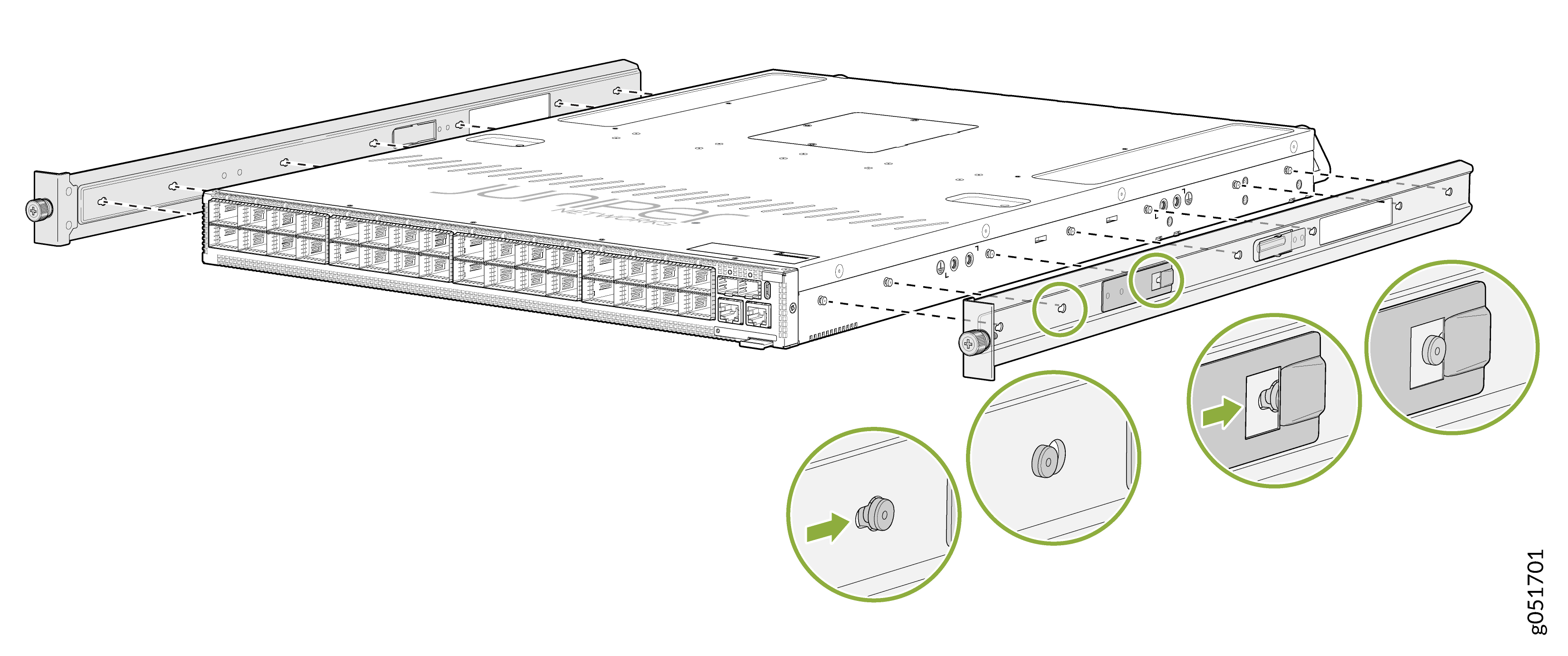
To attach the side-mounting brackets to the chassis, align the keyholes on the
mounting brackets over the shoulder screws on the chassis. Slide the mounting
brackets toward the rear of the chassis.
Figure 1: Attach the Side-Mounting Brackets to the Chassis
-
You can also flush mount the chassis on the rear side.
Figure 2: Flush Mount the Chassis from Rear Side
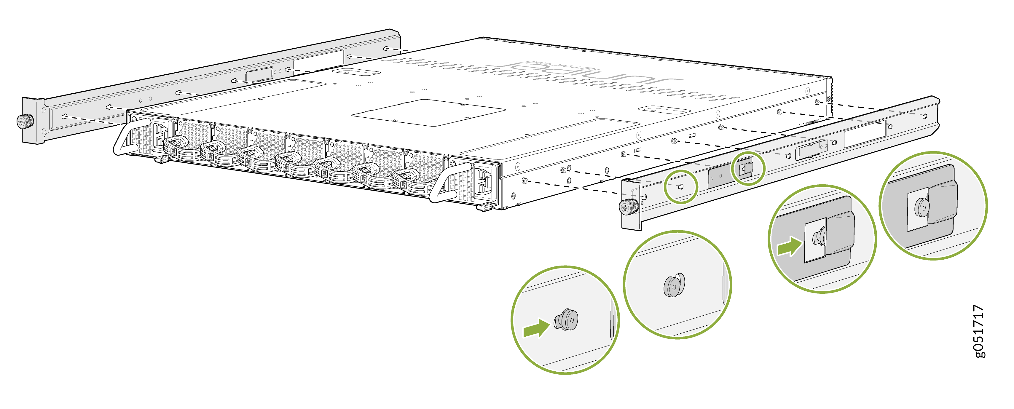 Note: Flip the rails when you flush mount the chassis on the rear side.
 -
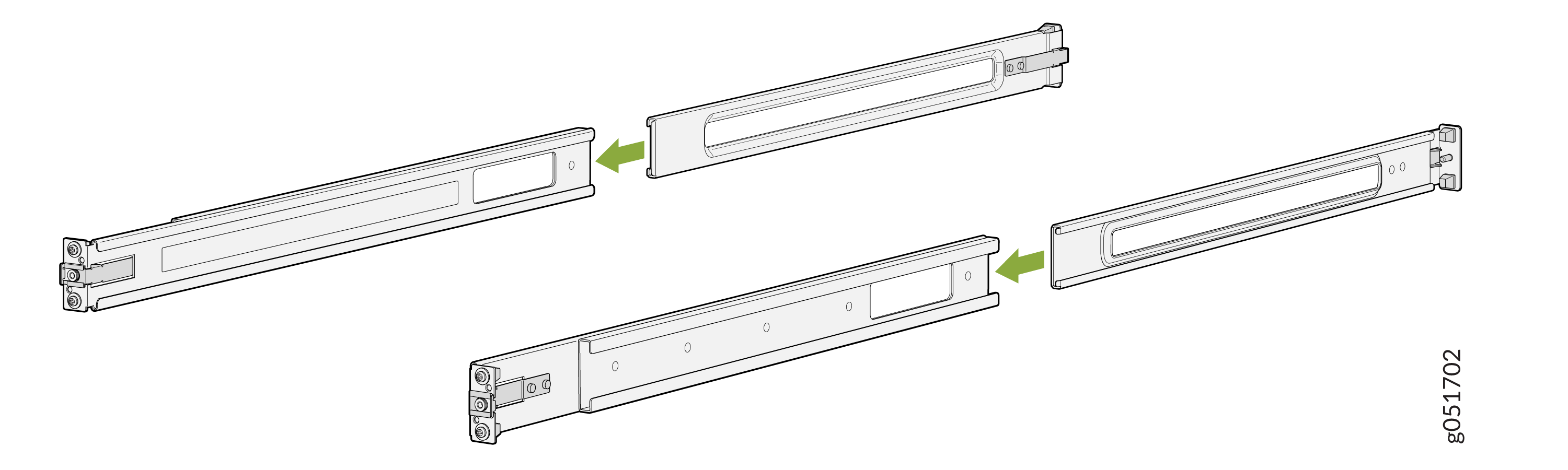
Assemble the mounting rails by sliding the rear floating rails into the front
rails.
Figure 3: Assemble the Front and Rear Mounting Rails
-
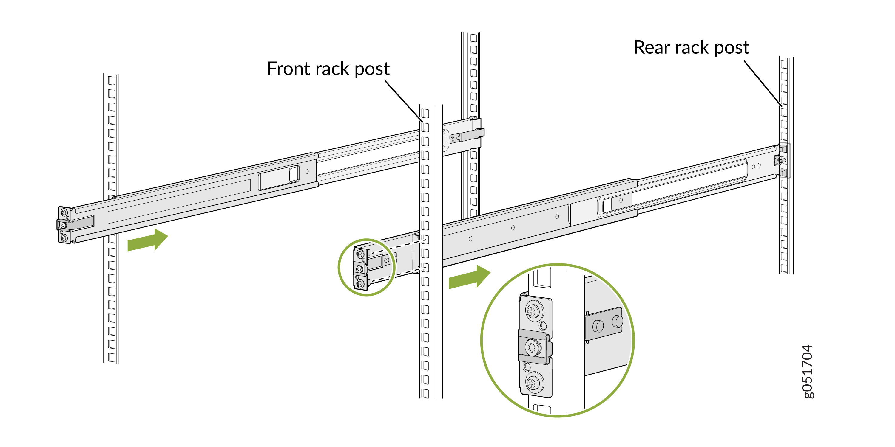
Attach the mounting rails to the rack.
-
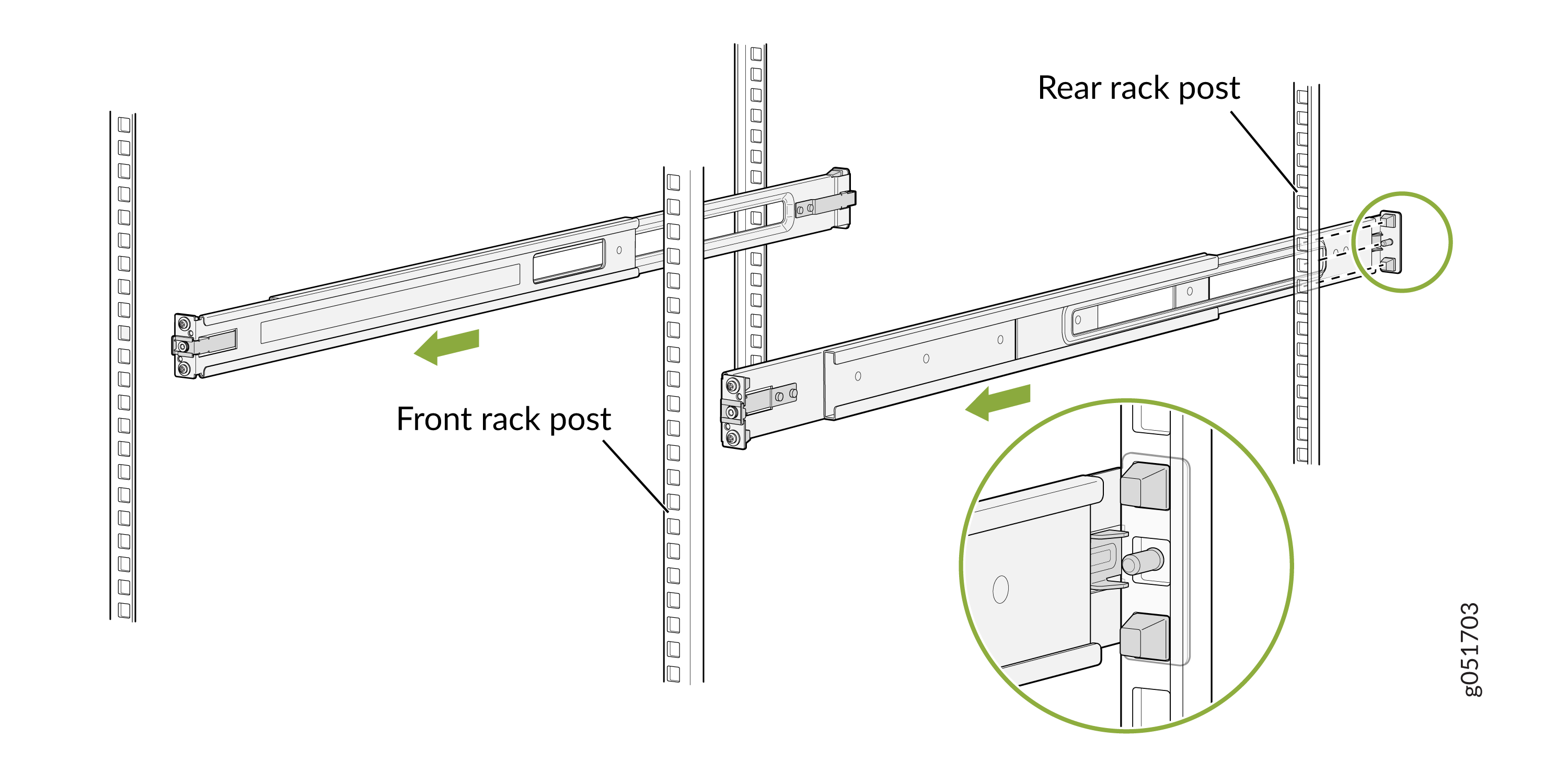
Standing in front of the rack, align the guide blocks of the rear-mounting
rails with the rear-post holes. Pull the rear-mounting rails toward the
front of the rack to lock the rails in place. You will hear a click sound
when the latch locks into the corresponding rack holes.
Figure 4: Install the Rear Floating Rails
-
Move the latch lock on the front-mounting rail to open position, slide the
front- mounting rail, and insert the guide blocks into the front rack
posts.
Figure 5: Attach the Front Mounting Rails to the Rack Posts
-
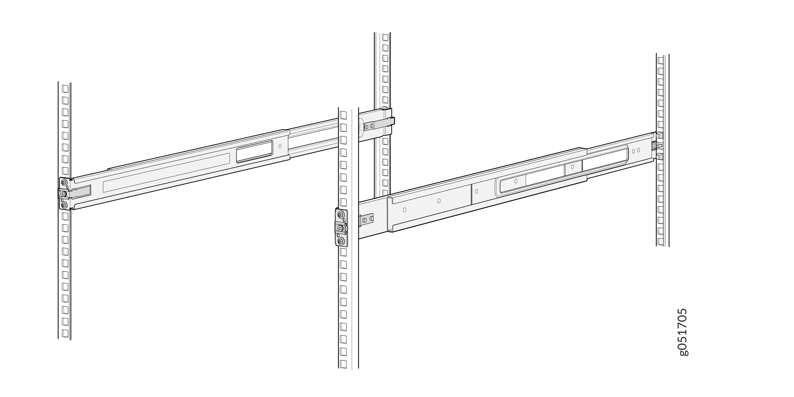
Ensure that the front and rear latches on the mounting rails are locked in
place.
The mounting rails are now fully installed.Figure 6: Mounting Rails Fully Installed
Note:Install the grounding lug after RMK installation.
-
Standing in front of the rack, align the guide blocks of the rear-mounting
rails with the rear-post holes. Pull the rear-mounting rails toward the
front of the rack to lock the rails in place. You will hear a click sound
when the latch locks into the corresponding rack holes.
-
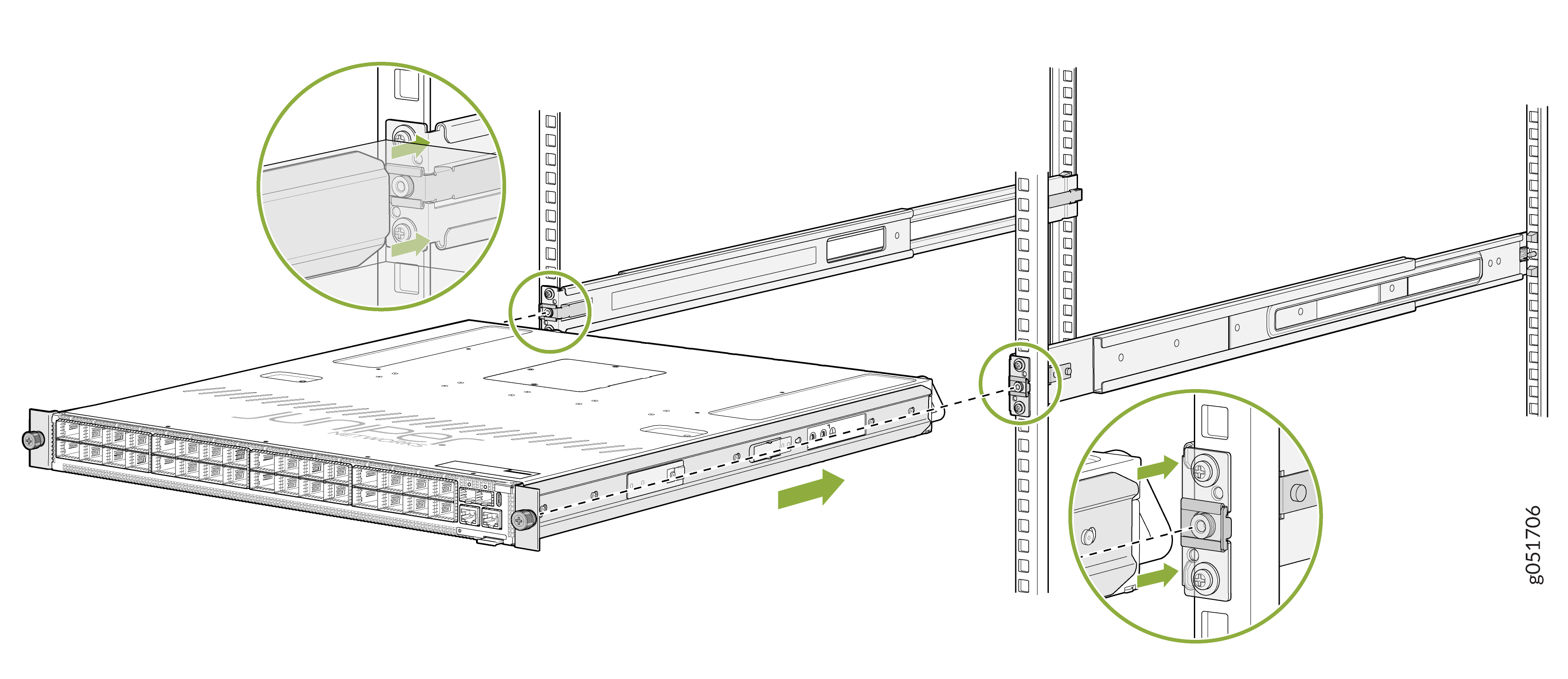
Lift the device and position it in the rack, aligning the side-mounting brackets
with the mounting rails. Slide the device into the channels of the mounting
rails.
Figure 7: Attach the QFX5241-32OD Chassis to the Rack
-
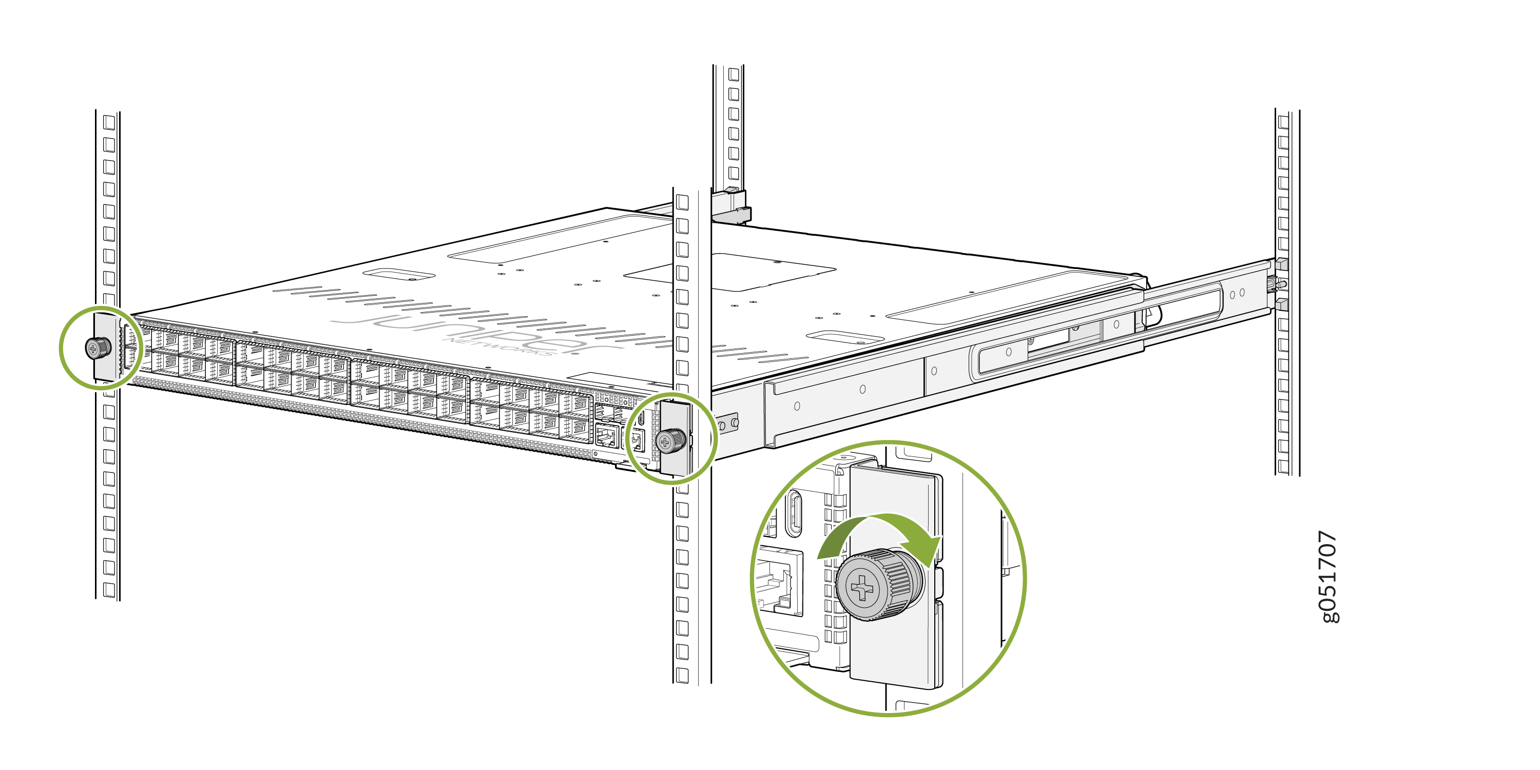
Tighten the two thumbscrews to secure the switch.
Figure 8: Tighten the Thumbscrews
Connect the QFX5241-32OD Switch to Power
Ground the QFX5241-32OD Switch
You must connect the QFX5241-32OD switch to earth ground before you connect it to power. Grounding helps your switch meet safety and EMI requirements and ensures that the switch functions properly.
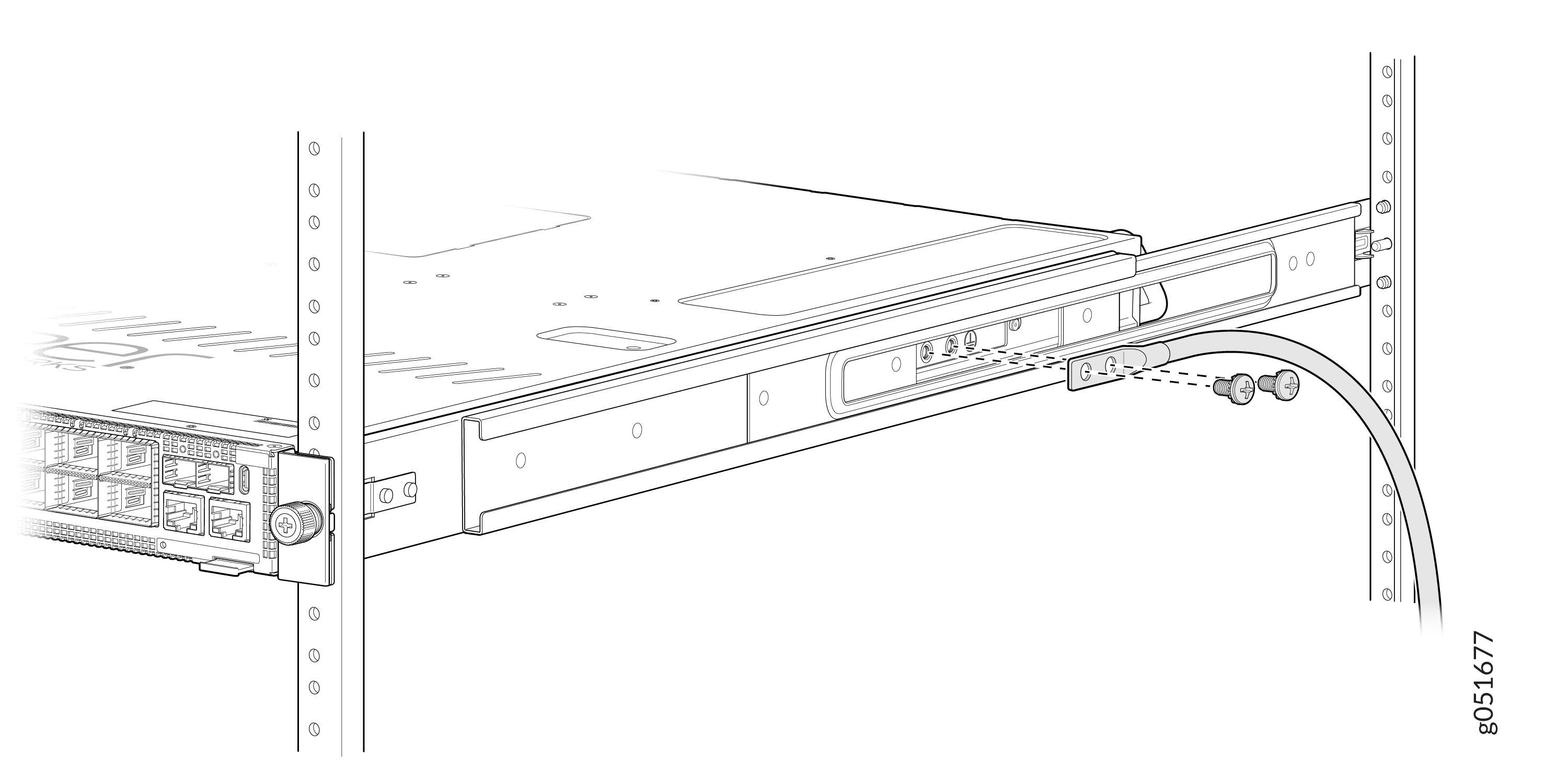
You must install the QFX5241-32OD switch in a restricted-access location and ensure that the chassis is always properly grounded. The QFX5241-32OD switch comes with a two-hole protective grounding terminal provided on the side of the chassis. See Figure 9. Under all circumstances, use this grounding connection to ground the chassis. For AC-powered systems, you must also use the grounding wire in the AC power cord along with the two-hole grounding lug connection. The system is tested to ensure that it meets or exceeds all applicable EMC regulatory requirements for the two-hole protective grounding terminal.
Ensure that you have the following parts and tools available:
-
A grounding cable (not provided)—6 AWG, minimum 90 °C wire, or as permitted by the local code.
-
A grounding lug (not provided)—Panduit LCD6-14A-L or equivalent grounding lug. The grounding lug attaches to the device chassis through the left-front mounting bracket, providing a protective earthing terminal for the device.
-
Two M6 screws, 6 mm length with star washers (not provided)
-
Phillips (+) screwdriver, number 2
-
ESD grounding strap (not provided)
To ground the QFX5241-32OD switch:
-
Secure the grounding lug to the protective earthing
terminal using the two M6 screws with star washers.
Figure 9: Connect a Grounding Cable to the QFX5241-32OD AC Switch
 Note:
Note:Install the grounding lug after RMK installation.
To gain additional grounding for the chassis of your QFX5241-32OD switch, connect the PSU in the switch into a grounded power outlet. Use a power cord appropriate for your geographical location.
Connect AC Power to QFX5241-32OD Switch
Ensure that you have a power cord appropriate for your geographical location available to connect AC power to the switch.
Before you begin connecting AC power to the switch:
-
Ensure that you have taken the necessary precautions to prevent electrostatic discharge (ESD) damage.
-
Ensure that you have connected the switch chassis to earth ground. See Ground the QFX5241-32OD Switch
CAUTION:Before you connect power to the switch, a licensed electrician must attach a cable lug to the grounding cables that you supply. A cable with an incorrectly attached lug can damage the switch (for example, by causing a short circuit).
To meet safety and electromagnetic interference (EMI) requirements and to ensure proper operation, you must connect the chassis to earth ground before you connect it to power. For installations that require a separate grounding conductor to the chassis, use the protective earthing terminal on the switch chassis to connect to the earth ground. For instructions on connecting earth ground, see Ground the QFX5241-32OD Switch. The switch gains additional grounding when you plug the PSU in the switch into a grounded power outlet by using the AC power cord appropriate for your geographical location.
-
Install the power supply units (PSUs) in the chassis. For instructions on installing the PSU in the QFX5241-32OD switch, see Install a Power Supply Unit in QFX5241-32OD Switch.
The QFX5241-32OD switch ships from the factory with two preinstalled AC PSUs. The AC PSUs offer 1+1 redundancy. The PSUs are hot-removable and hot-insertable field-replaceable units (FRUs). You can replace a PSU in the slots adjacent to the fan modules without powering off the switch or disrupting its operation.
Each PSU must be connected to a dedicated power source outlet.
To connect AC power to the QFX5241-32OD switch:
-
Locate the power cords shipped with the switch; the cords have plugs
appropriate for your geographical location. See AC Power Cord Specifications.
For each PSU:
-
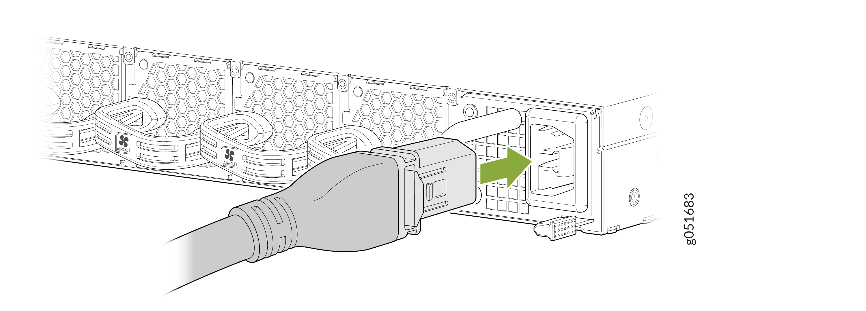
Connect the AC power cord. Insert the power cord coupler firmly into
the AC inlet on the PSU faceplate.
Figure 10: Connect the AC Power Cord
-
Connect the AC power cord. Insert the power cord coupler firmly into
the AC inlet on the PSU faceplate.