Unpack and Mount the QFX5241-32OD Switch
Unpack QFX5241-32OD Switch
The chassis of QFX5241-32OD switch is a rigid sheet-metal structure that houses the hardware components. We ship the QFX5241-32OD switch in a cardboard carton, secured with foam packing material.
The QFX5241-32OD switch is maximally protected inside the shipping carton. Do not unpack the switch until you are ready to begin installation.
To unpack the QFX5241-32OD switch:
- Move the shipping carton to a staging area as close to the installation site as possible, but where you have enough room to remove the system components.
- Position the carton so that the arrows are pointing up.
- Open the top flaps on the shipping carton.
- Remove the switch out of the packing material from the pellet.
- Verify the contents of the carton against the inventory included in the carton. Table 1 lists the inventory of components supplied with the QFX5241-32OD.
- Save the shipping carton and packing materials in case you need to move or ship the switch later.
|
Component |
Quantity |
|---|---|
|
Chassis |
1 |
|
Fan modules |
7, factory installed |
|
Power supply units (PSUs):
|
2, factory installed |
Note: The order number for a spare rack mount kit
is QFX5241-1U-4PRMK.
|
1 |
| Rack mount kit, QFX5241-1U-4PRMK, is composed of the following: | |
|
Chassis brackets Rear floating rail Front rail |
2 2 2 |
|
Rack mount assembly drawing (part of the QFX5241-1U-4PRMK rack mount kit) |
1 |
|
Power cords with plugs appropriate to your geographical location |
2 |
|
Documentation roadmap card |
1 |
|
Warranty |
1 |
-
For QFX5241-32OD switch with AC power supplies, two power cords (CG_CBL-SDG-C20-2M) of 2 m length ship with the switch by default.
We no longer include the RJ-45 console cable with the DB-9 adapter as part of the device package. If the console cable and adapter are not included in your device package, or if you need a different type of adapter, you can order the following separately:
- RJ-45 to DB-9 adapter (JNP-CBL-RJ45-DB9)
- RJ-45 to USB-A adapter (JNP-CBL-RJ45-USBA)
- RJ-45 to USB-C adapter (JNP-CBL-RJ45-USBC)
If you want to use RJ-45 to USB-A or RJ-45 to USB-C adapter you must have X64 (64-Bit) Virtual COM port (VCP) driver installed on your PC. See, https://ftdichip.com/drivers/vcp-drivers/ to download the driver.
Register Products—Mandatory to Validate SLAs
Juniper Networks auto registers newly purchased products based on the end customer information provided at the point of sale. Registering products and changes to products activates your hardware replacement service-level agreements (SLAs).
Update the installation base data if any installation base data is added or changed or if the installation base is moved. Juniper Networks is not responsible for customers not meeting the hardware replacement service-level agreement (SLA) for products that do not have registered serial numbers or accurate installation base data.
To know more about how to register your product and update your installation base, see Juniper Networks Product Registration and Install Base Management.
Mount the QFX5241-32OD Switch on a Square Hole Rack by Using the QFX5241-1U-4PRMK Rack Mount Kit
Ensure that you have the following tools and parts available:
-
An ESD grounding strap (not provided)
-
A pair of front-mounting and rear-mounting rails
These mounting rails attach to the front and rear rack posts (provided with the RMK)
-
A pair of side-mounting brackets—provided with the RMK
You must attach these brackets to the device.
To mount the device on four posts in a rack by using the QFX5241-1U-4PRMK:
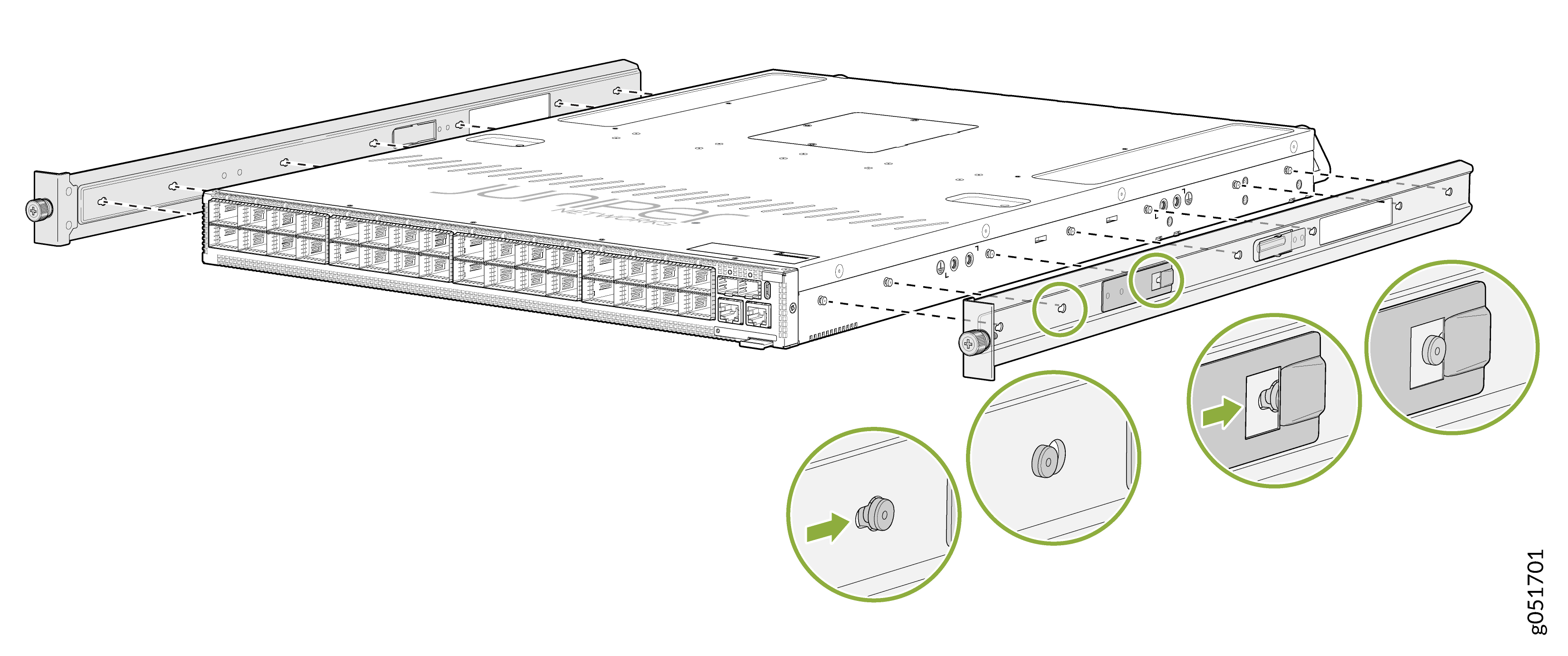
-
To attach the side-mounting brackets to the chassis, align the keyholes on the
mounting brackets over the shoulder screws on the chassis. Slide the mounting
brackets toward the rear of the chassis.
Figure 1: Attach the Side-Mounting Brackets to the Chassis
-
You can also flush mount the chassis on the rear side.
Figure 2: Flush Mount the Chassis from Rear Side
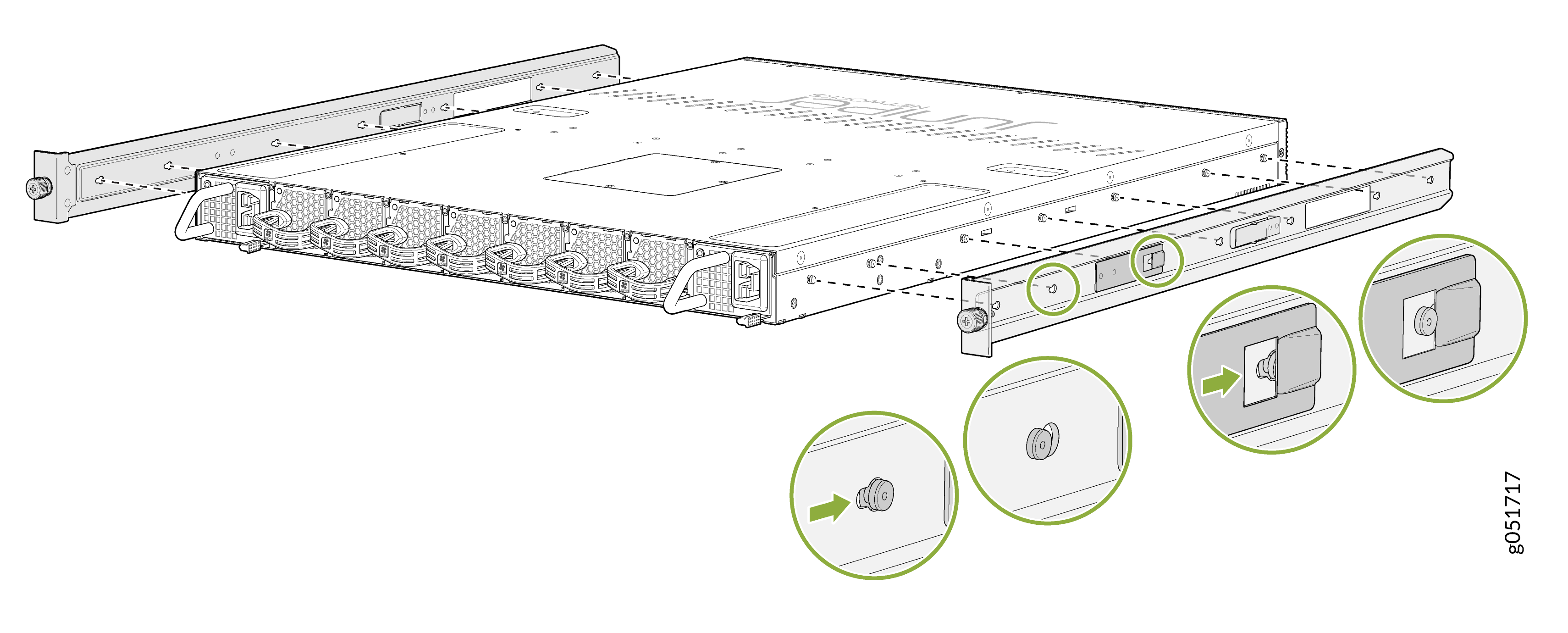 Note: Flip the rails when you flush mount the chassis on the rear side.
 -
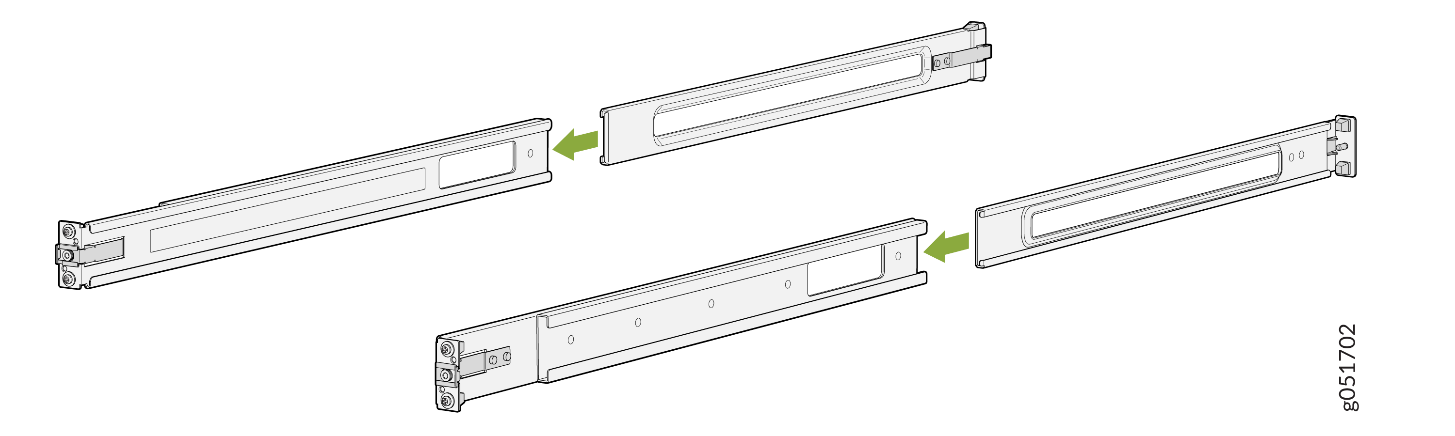
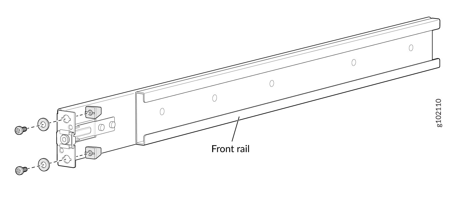
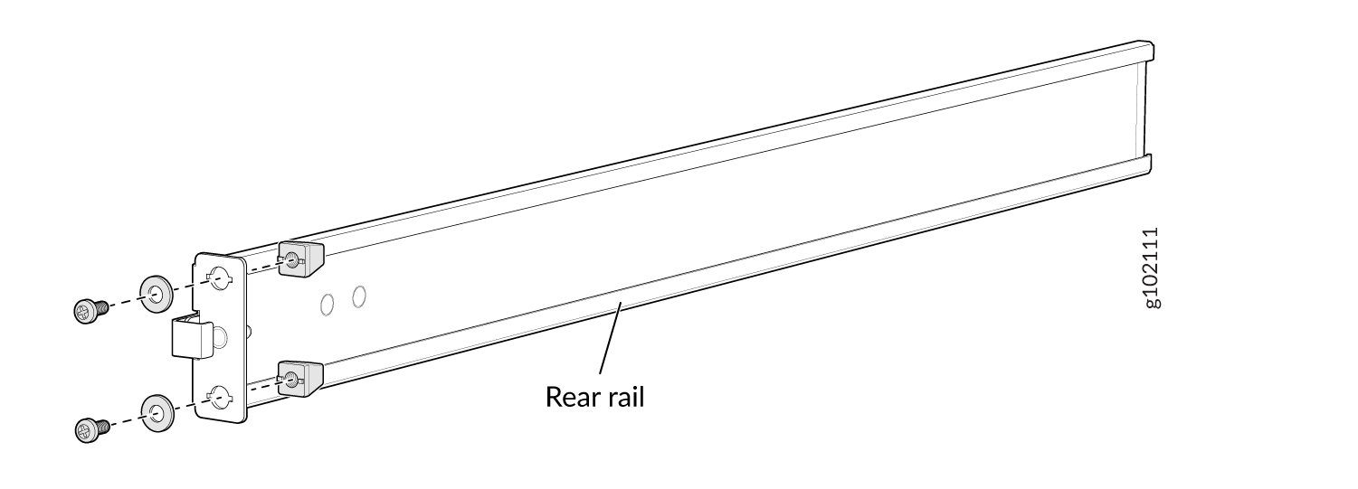
Assemble the mounting rails by sliding the rear floating rails into the front
rails.
Figure 3: Assemble the Front and Rear Mounting Rails
-
Attach the mounting rails to the rack.
-
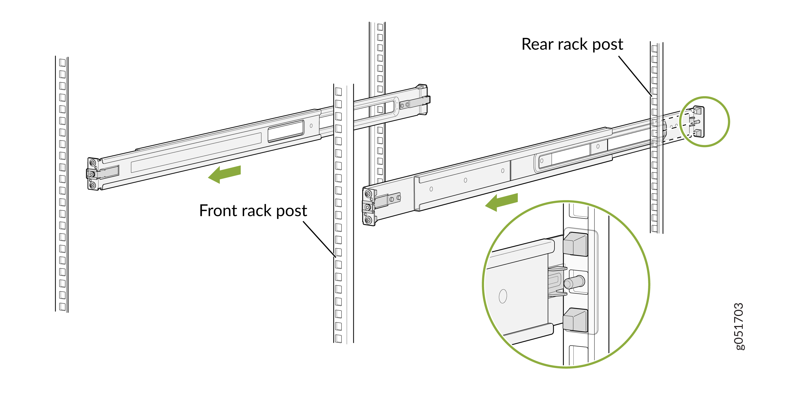
Standing in front of the rack, align the guide blocks of the rear-mounting
rails with the rear-post holes. Pull the rear-mounting rails toward the
front of the rack to lock the rails in place. You will hear a click sound
when the latch locks into the corresponding rack holes.
Figure 4: Install the Rear Floating Rails
-
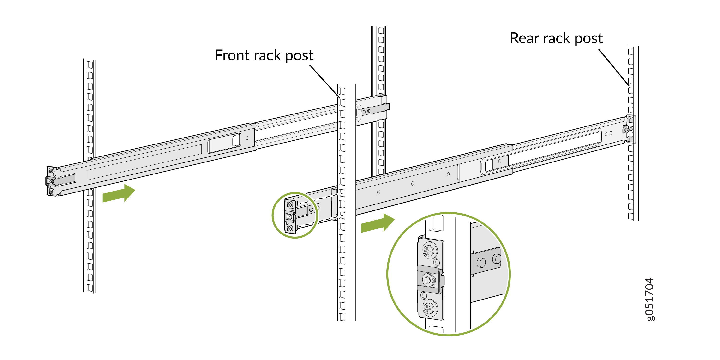
Move the latch lock on the front-mounting rail to open position, slide the
front- mounting rail, and insert the guide blocks into the front rack
posts.
Figure 5: Attach the Front Mounting Rails to the Rack Posts
-
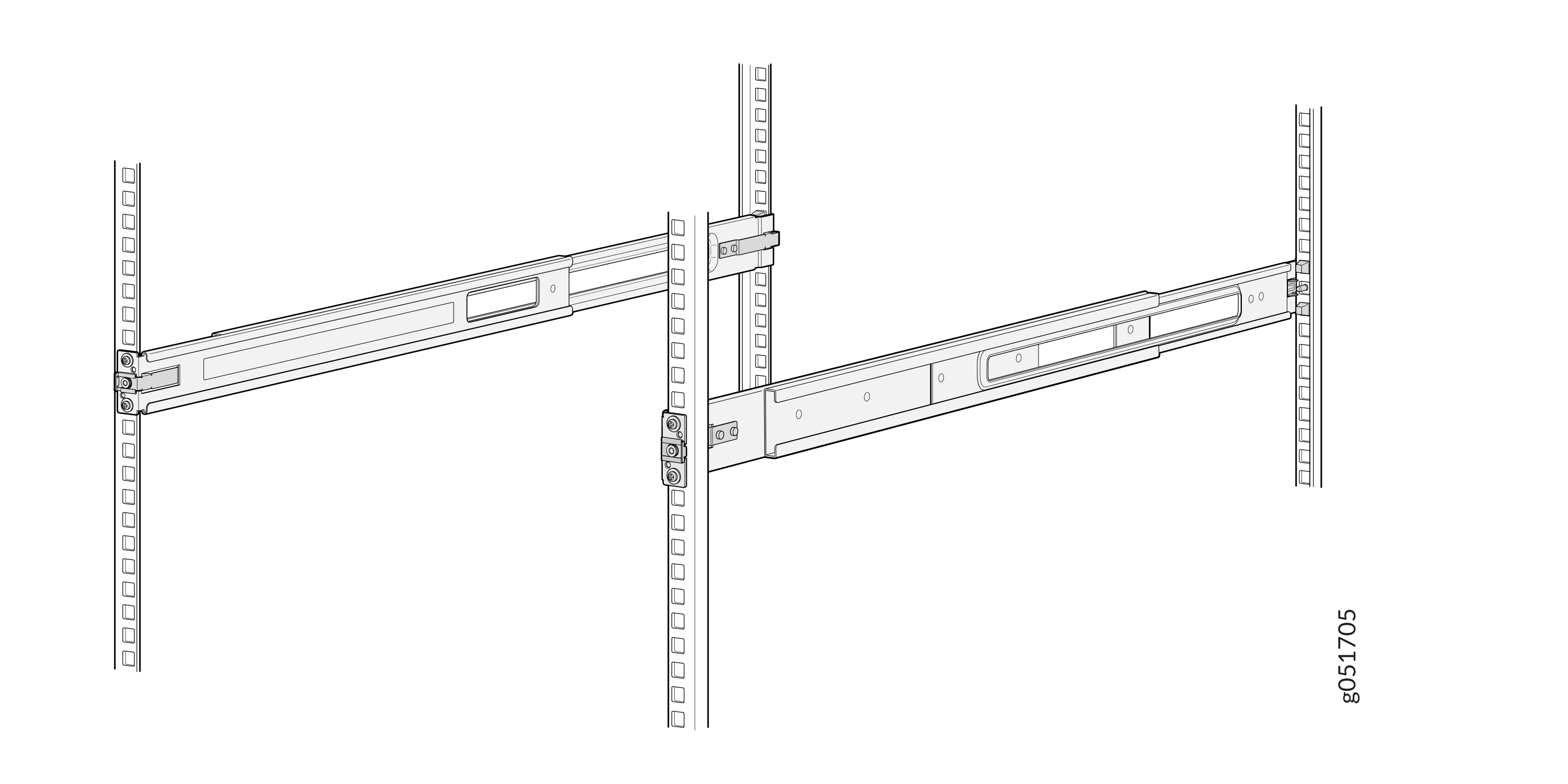
Ensure that the front and rear latches on the mounting rails are locked in
place.
The mounting rails are now fully installed.Figure 6: Mounting Rails Fully Installed
-
Standing in front of the rack, align the guide blocks of the rear-mounting
rails with the rear-post holes. Pull the rear-mounting rails toward the
front of the rack to lock the rails in place. You will hear a click sound
when the latch locks into the corresponding rack holes.
-
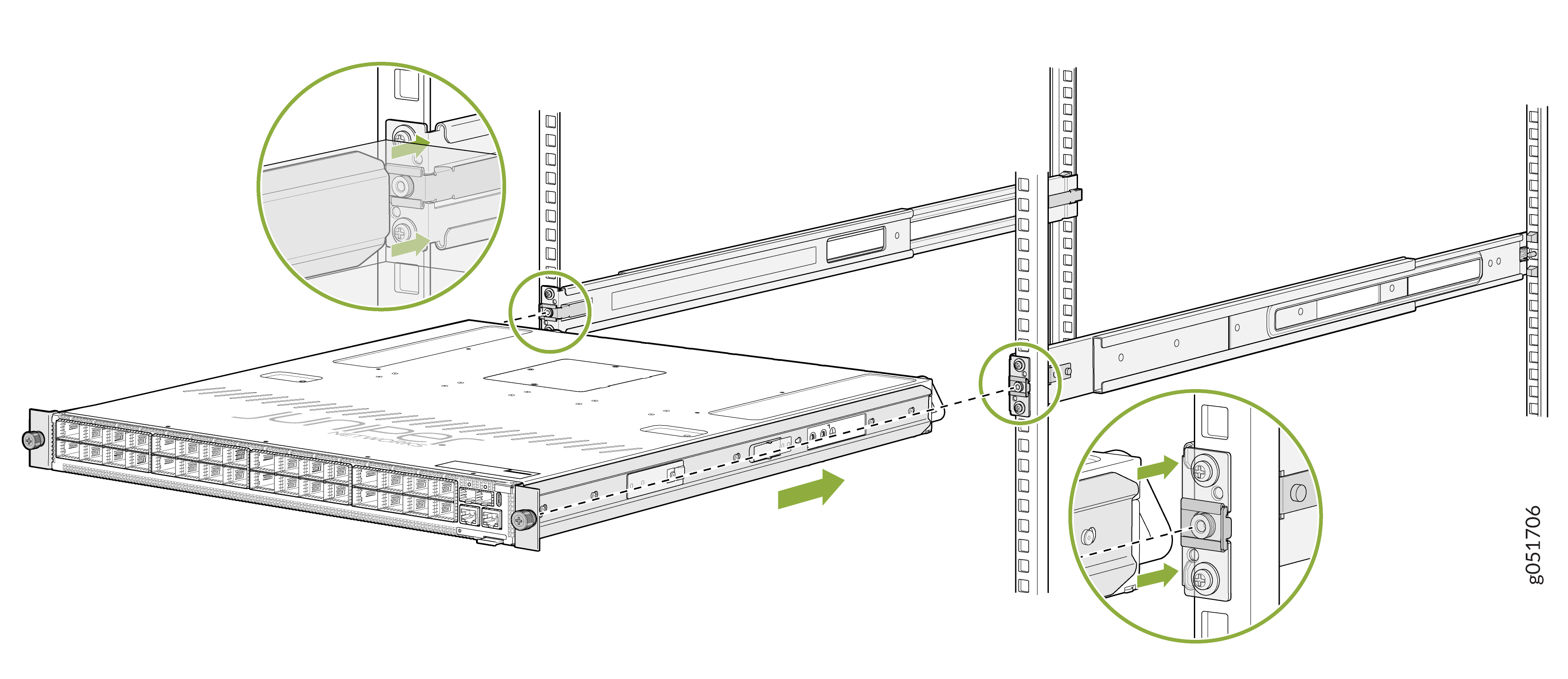
Lift the device and position it in the rack, aligning the side-mounting brackets
with the mounting rails. Slide the device into the channels of the mounting
rails.
Figure 7: Attach the QFX5241-32OD Chassis to the Rack
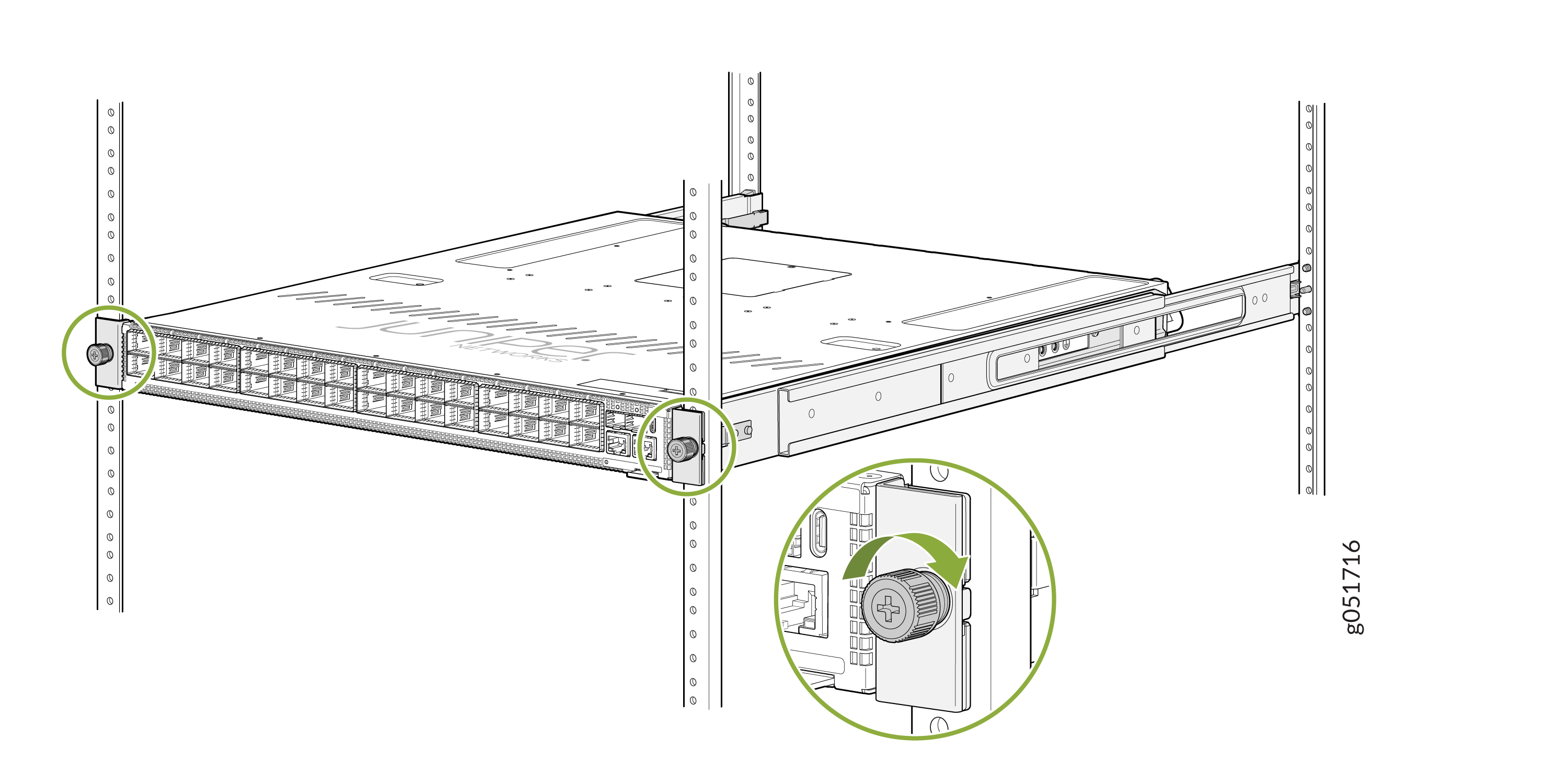
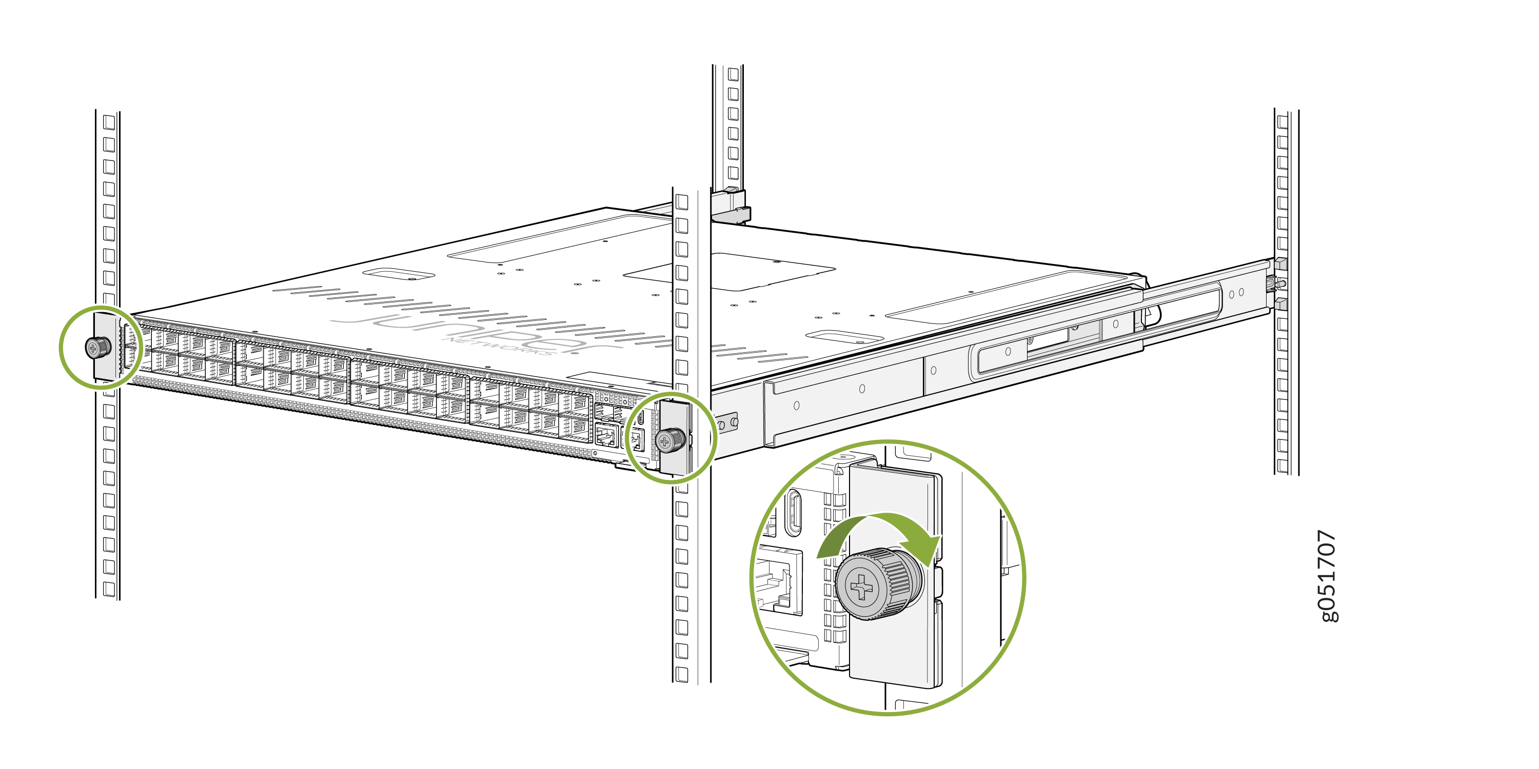
-
Tighten the two thumbscrews to secure the switch.
Figure 8: Tighten the Thumbscrews
Mount Your QFX5241-32OD Switch on a Threaded-Hole Rack by Using the QFX5241-1U-4PRMK Rack Mount Kit
You can mount the QFX5241-32OD switch in a four-post threaded-hole rack within a cabinet. Ensure that you have the following tools and parts available:
-
An ESD grounding strap (not provided)
-
A Phillips (+) screwdriver, number 2—not provided
-
A pair of side-mounting brackets that attach to the chassis [provided with the rack mount kit (RMK)]
-
A pair of front-mounting and rear-mounting rails that attach to the rack posts (provided with the RMK)
To mount the device on a four-post rack with threaded holes:
-
To attach the side-mounting brackets to the chassis, align the keyholes on
the mounting brackets over the shoulder screws on the chassis. Slide the
mounting brackets toward the rear of the chassis.
Figure 9: Attach the Side-Mounting Brackets
-
You can also flush mount the chassis on the rear side.
Figure 10: Flush Mount the Chassis from Rear Side
-
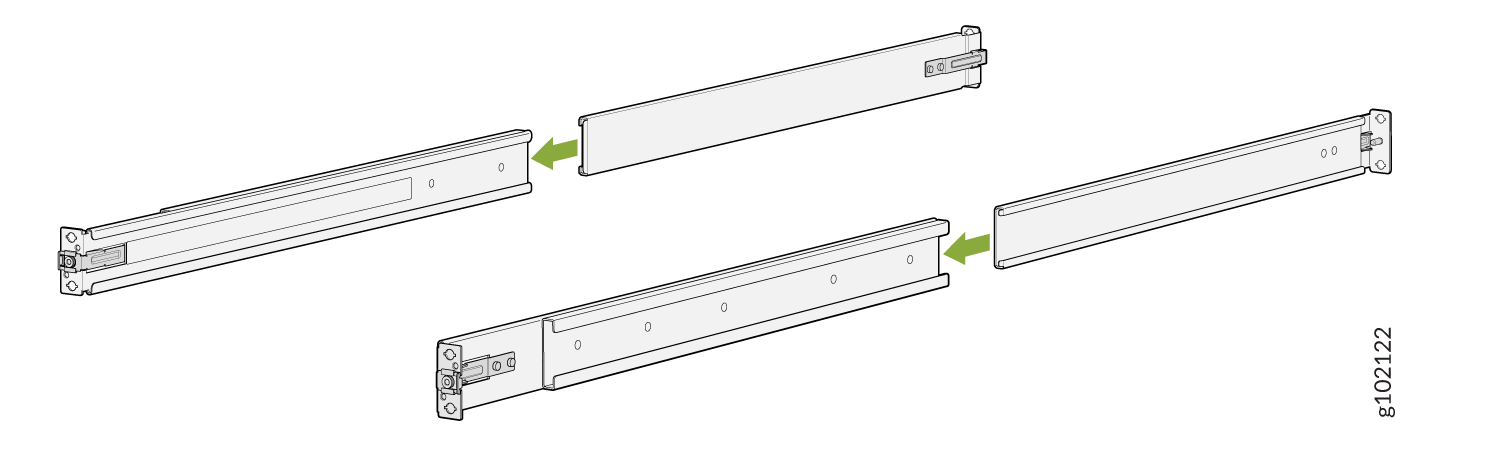
Assemble the mounting rails:
-
Remove the guide blocks from the front-mounting rails by loosening
the screws and washers. Retain the guide blocks, screws, and washers
for later use.
Figure 11: Remove the Guide Blocks from the Front Mounting Rail
-
Remove the guide blocks from the rear-mounting rail by loosening
the screws and washers. Retain the guide blocks, screws, and washers
for later use.
Figure 12: Remove the Guide Blocks from the Rear-Mounting Rail
-
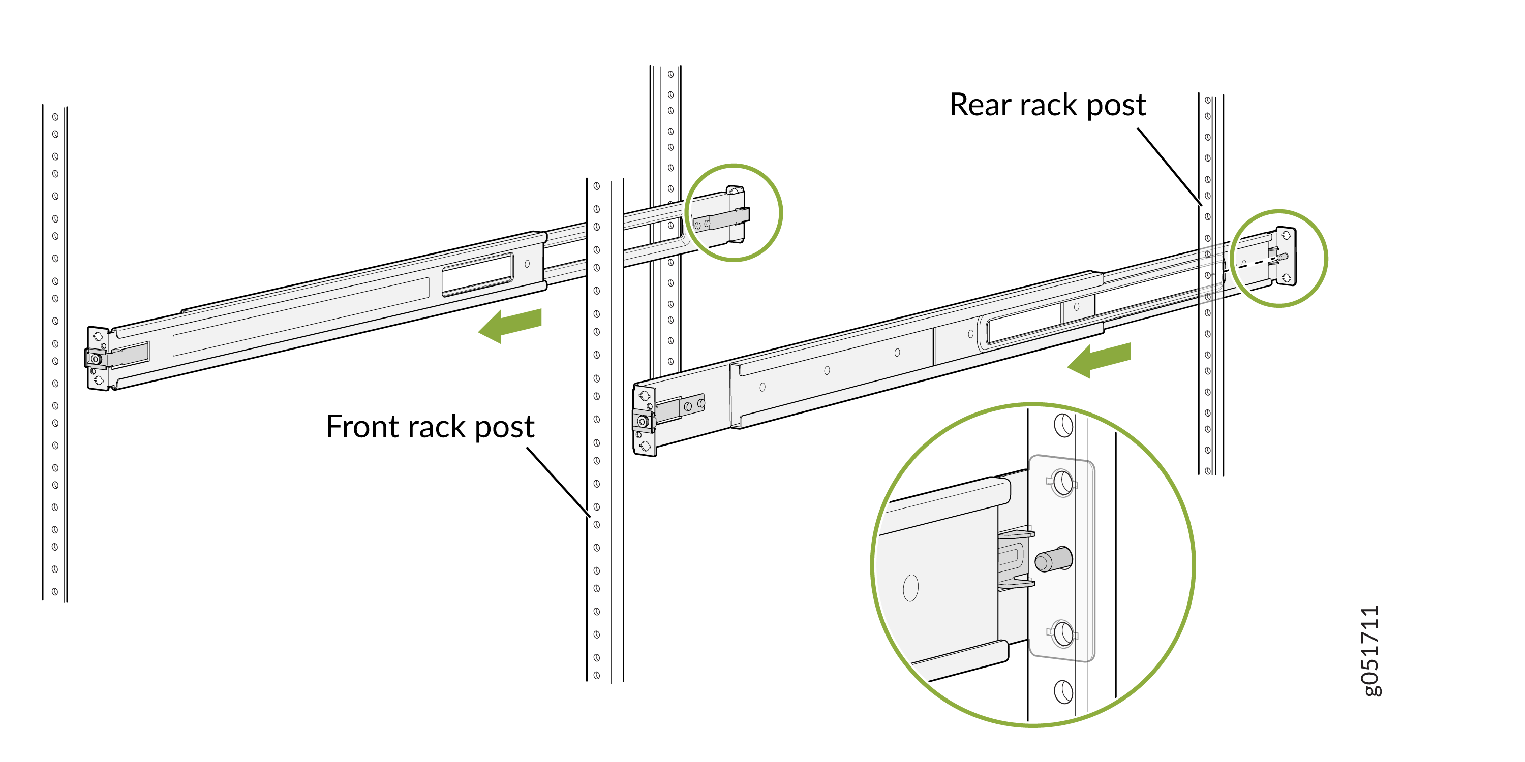
Slide the rear floating rails into the front rails.
Figure 13: Assemble the Mounting Rails
-
Remove the guide blocks from the front-mounting rails by loosening
the screws and washers. Retain the guide blocks, screws, and washers
for later use.
-
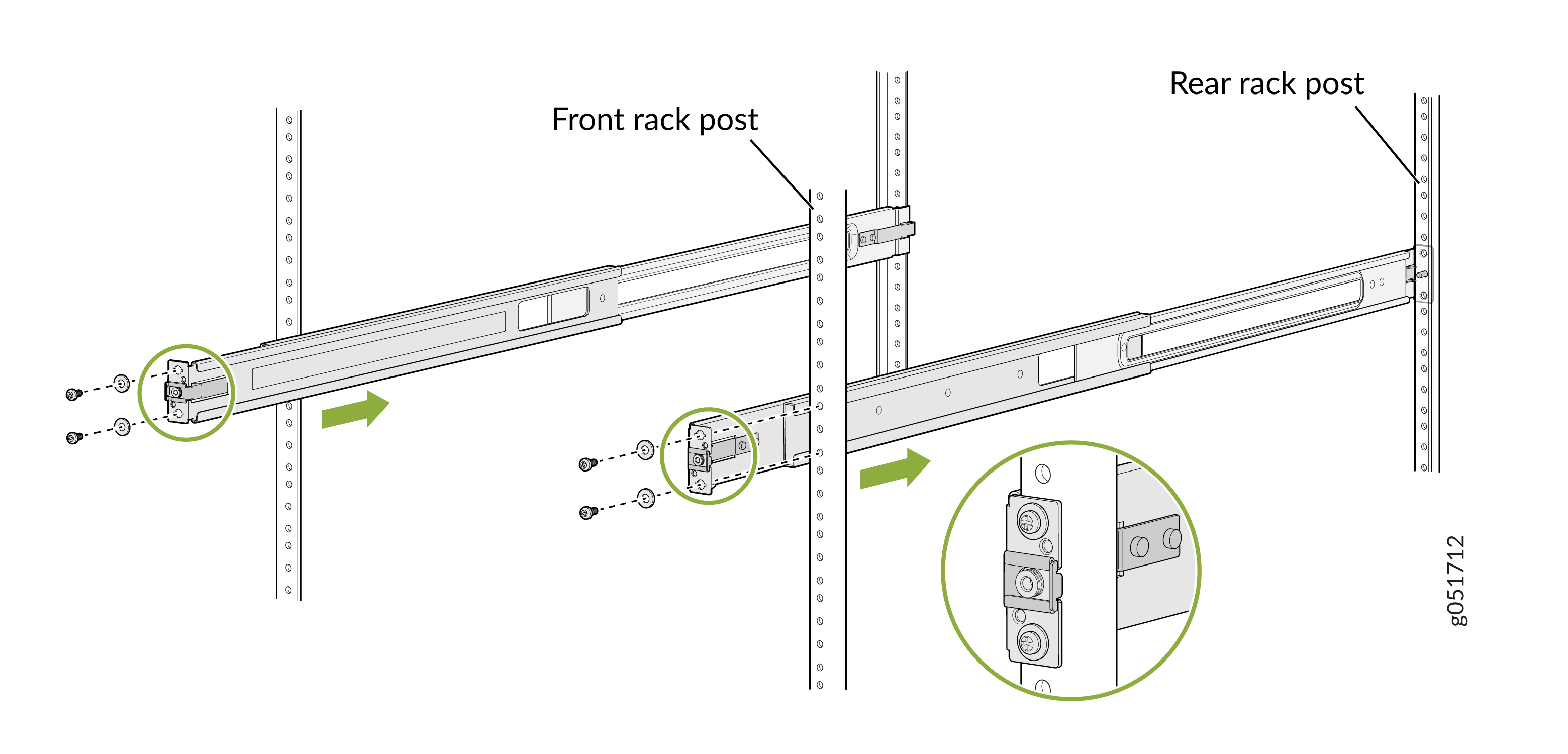
Install the mounting rails on the rack:
-
Insert the guide pin of the rear-mounting rails into the rear-post
holes. Pull the rear-mounting rails toward the front of the rack to
lock the rails in place. You will hear a distinct click sound when
the latch locks into place.
Figure 14: Install the Rear-Mounting Rails
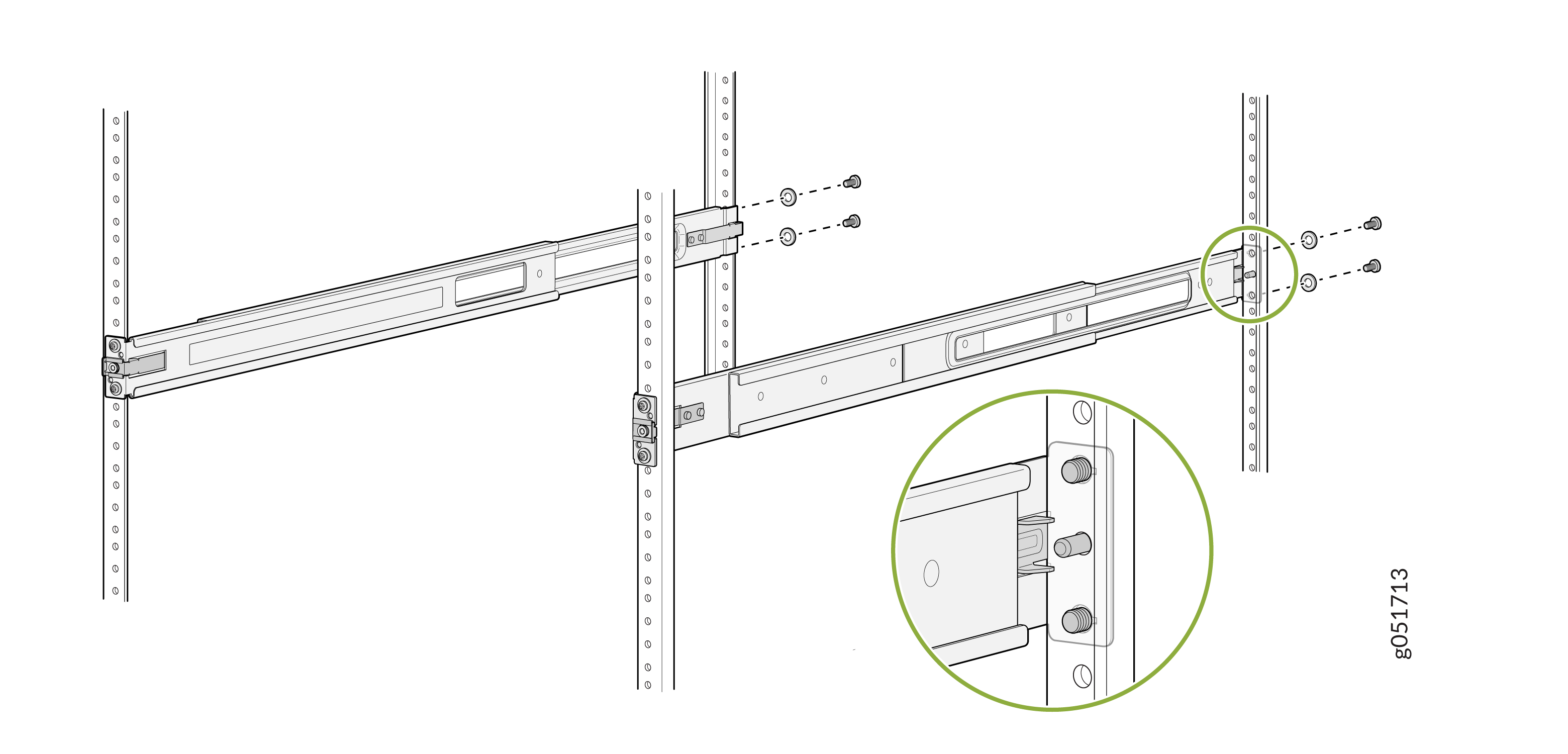
-
Insert the guide pin of the front-mounting rails into the
front-post holes. Push the front-mounting rails toward the rear of
the rack to lock the rails in place. You will hear a distinct click
sound when the latch locks into place. Secure the front-mounting
rails to the front rack post by using screws (not provided)
appropriate for your rack threaded size.
Figure 15: Install and Secure the Front-Mounting Rails
-
Secure the front-mounting rails to the front rack post by using
screws (not provided) appropriate for your rack threaded size.
Figure 16: Secure the Rear-Mounting Brackets
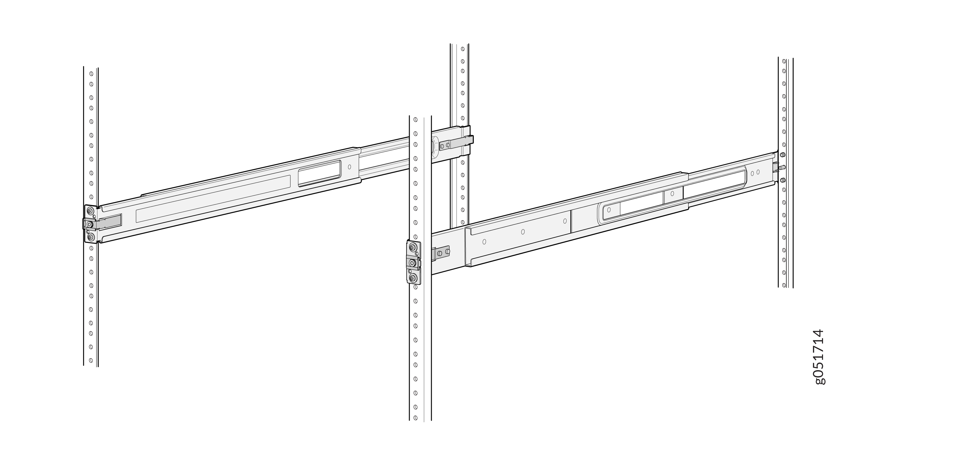
-
Ensure that the front and rear latches are locked into place on the
mounting rails. The mounting rails must be securely installed on the
rack.
Figure 17: Mounting Rails Installed and Secured
-
Insert the guide pin of the rear-mounting rails into the rear-post
holes. Pull the rear-mounting rails toward the front of the rack to
lock the rails in place. You will hear a distinct click sound when
the latch locks into place.
-
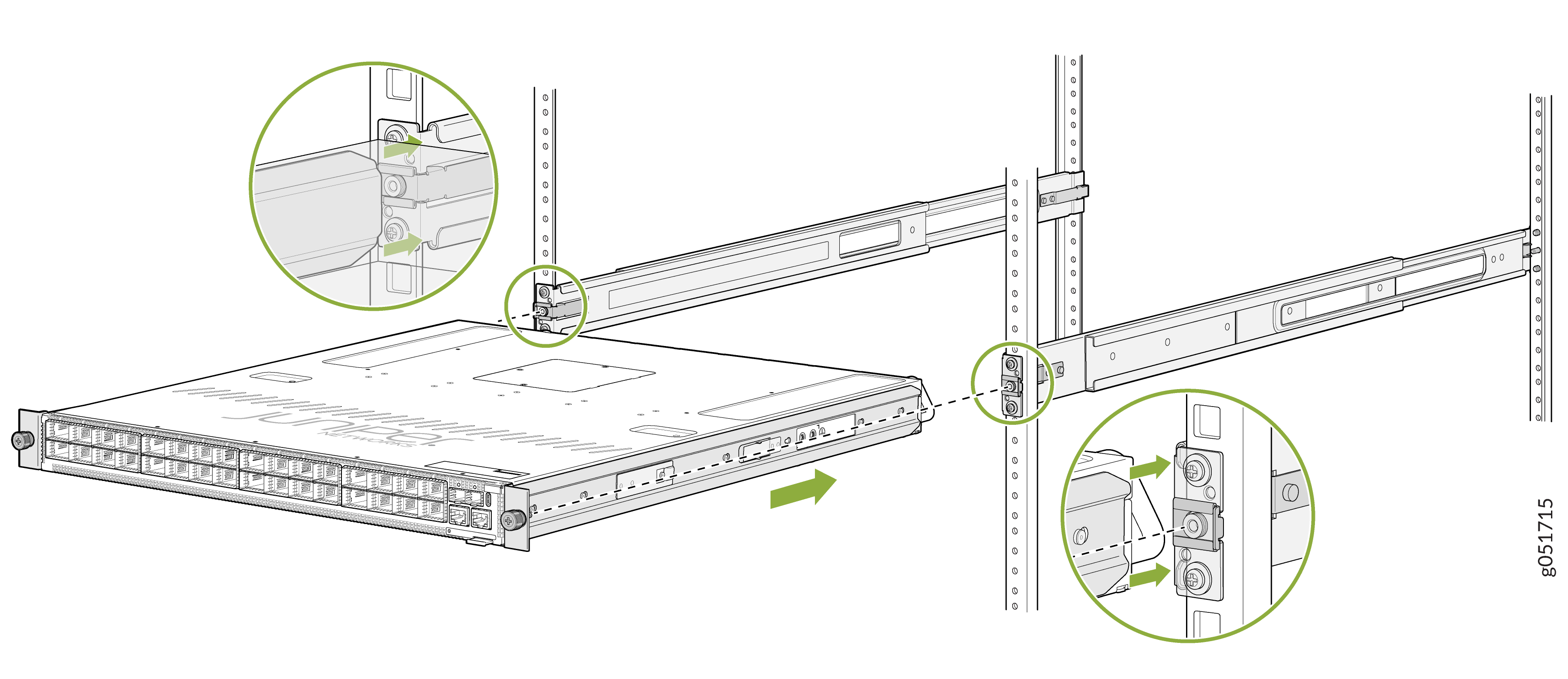
Lift the device and position it in the rack, aligning the side-mounting
brackets with the mounting rails. Slide the device into the channels of the
mounting rails.
Figure 18: Slide the Device into the Rack
-
Tighten the two thumbscrews to secure the device.
Figure 19: Tighten the Thumbscrews