QFX5110 Port Panels
QFX5110-48S Port Panel
The port panel of the QFX5110-48S is primarily comprised of 48 small form-factor pluggable plus (SFP+) and 4 quad small form-factor pluggable solution (QSFP28) ports. It also provides a central location for the Precision Time Protocol (PTP) connections to a grandmaster clock.
This topic describes:
Switch Overview
The port panel of the QFX5110-48S supports 48 logical 10-GbE ports when operating as a standalone switch. These data ports (0 through 47) support either 1-Gbps or 10-Gbps SFP+ transceivers. You can also use SFP+ DAC cables and 10-Gbps active optical cables (AOC) in any access port. Starting in Junos OS Release 18.3R1, the 10-GbE ports also support 100 Mbps.
The remaining 4 QSFP28 ports (48 through 51) support speeds of 40 GbE or 100 GbE. Each port can be configured as an independent 100-GbE port or as an independent 40-GbE port. These port are usually used as uplinks or Virtual Chassis Ports (VCP) on QFX5110 Virtual Chassis or Virtual Chassis Fabric (VCF). In 40-GbE mode, these ports can be channelized using QSFP+ to SFP+ DAC breakout (DACBO) cables.
Figure 1 shows the port panel of the QFX5110-48S.
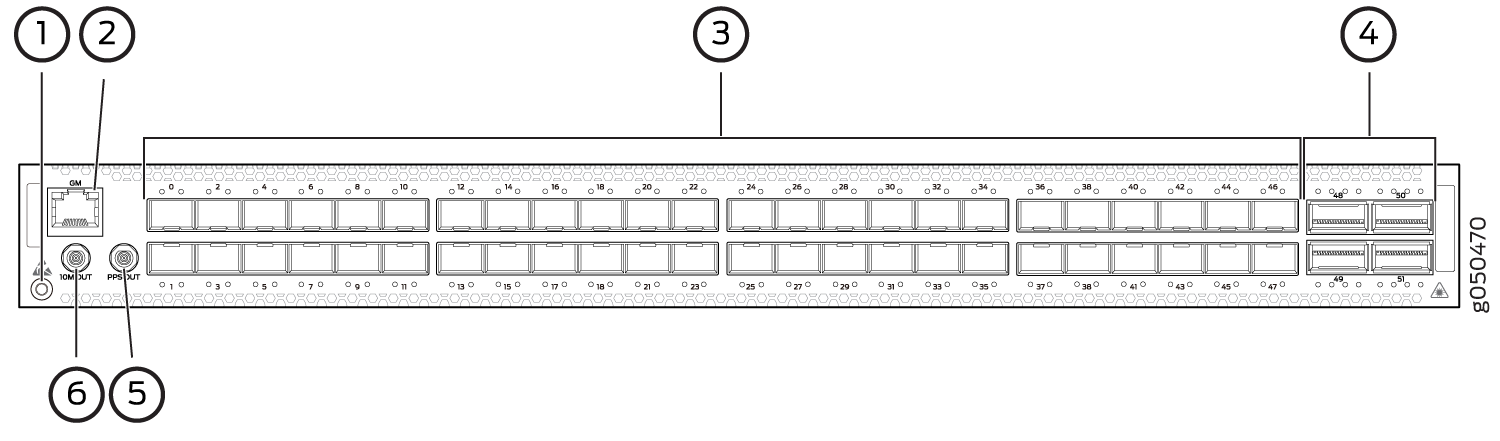
1 — Electrostatic discharge (ESD) terminal | 4 — 4 QSFP28 ports |
2 — RJ-45 connection to grandmaster clock | 5 — Output clock at 10 Mhz |
3 — 48 SFP+ ports | 6 — 1 pulse per second (PPS) output connection |
Network Ports
When you use the latest OEM part number FCLF8521P2BTL (printed on the transceiver label), you can install 1GbE transceivers (such as QFX-SFP-1GE-T) in any port with no restrictions. The same applies for devices that support 10GbE copper transceivers. However, if you are using the older OEM part number SP7041-M1-JN (not shipped in last 3+ years) instead, do not install 1GbE copper transceivers (such as QFX-SFP-1GE-T) directly above or below another 1GbE copper transceiver. Use only the top row or bottom row to avoid damage to the device caused when the transceivers are installed above or below each other.
The QFX5110-48S device ports (0 to 47) support:
-
10-Gbps SFP+ transceivers
-
1-Gbps SFP transceivers
-
SFP+ direct attach copper (DAC) cables
-
SFP+ active optical cables (AOC)
The QFX5110-48S uplink ports (48 to 51) support:
-
100-Gbps QSFP28 transceivers
-
40-Gbps QSFP+ transceivers
-
100-Gbps AOC
-
40-Gbps AOC (Junos OS 18.3R1 and later)
-
100-Gbps QSFP28 DAC cables
-
40-Gbps QSFP+ DAC cables
-
40-Gbps QSFP+ to SFP+ DACBO cables (40-Gbps breaks out to 10-Gbps for copper connections)
-
40-Gbps AOCBO cables (40-Gbps breaks out to 10-Gbps for fiber connections)
Channelizing Interfaces
For downstream traffic, the QFX5110-48S has 4 physical or 16 logical ports that can be used for port channelization. The default 100-Gigabit Ethernet ports can be configured as 40-Gigabit Ethernet, and in this configuration can either operate as dedicated 40-Gigabit Ethernet ports or can be channelized to 4 independent 10-Gigabit Ethernet ports using copper or fiber breakout cables.
To channelize the ports, manually configure the port speed using
the set chassis fpc slot-number port port-number channel-speed speed
command, where the speed can be set to 10-Gigabit Ethernet, 40-Gigabit
Ethernet, or 100-Gigabit Ethernet. The ports do not support auto-channelization.
Virtual Chassis and Virtual Chassis Fabric
To connect QFX5110 switches as members in a QFX5110 Virtual Chassis, you need a pair of dedicated ports on each switch and cables that link each member in the Virtual Chassis into a ring topology. Each member in the ring has at least one direct Virtual Chassis port (VCP) connection to a upstream and downstream member. QFX5110 switches are recommended in the primary, backup, or line card role. You may only mix QFX5100 members with QFX5110 members in a QFX5110 Virtual Chassis; no other QFX Series or EX Series switches are supported. See Connecting QFX5110 and QFX5100 Members in a QFX5110 Virtual Chassis for a a diagram of cabling QFX5110 switches in a ring topology.
To connect a QFX5110 switch as a spine or leaf device in a Virtual Chassis Fabric (VCF), you need a pair of dedicated ports and cables that link each spine device and leaf device in the VCF. All spine devices have at least one direct VCP connection to each leaf device in the VCF. See Connecting QFX5110 in a QFX5110 Virtual Chassis Fabric for a cabling diagram.
QFX5110-32Q Port Panel
The port panel of the QFX5110-32Q primarily comprises 28 quad small form-factor pluggable plus (QSFP+) ports and 4 quad small form-factor pluggable solution (QSFP28) ports. The mixture of QSFP+ and QSFP28 ports allows for flexible configuration as either all 40-Gigabit Ethernet ports or a mixture of 40-Gigabit Ethernet and 100-Gigabit Ethernet for high-speed uplinks. The port panel also provides a central location for the Precision Time Protocol (PTP) connections to a grandmaster clock.
This topic describes:
Switch Overview
The ports on the QFX5110-32Q support 40-Gbps or 100-Gbps speeds natively. All ports autosense the type of transceiver and set the port to the corresponding speed. The QSFP+ ports can support channelization to four independent 10 GbE downstream ports, see Channelizing Interfaces. Although all network ports can be configured as either uplink or as access ports, best practice is to configure the four QSFP28 ports (28 through 31) as uplinks to take advantage of the 100-Gbps speeds.
The port panel also provides PTP connections to a grandmaster clock (requires Junos OS Release 18.1R1). There are also 10-MHz pulses-per-second (PPS) SubMiniature B (SMB) input and output connections to measure the timing drift to and from the grandmaster clock.
Figure 2 shows the port panel of the QFX5110-32Q.
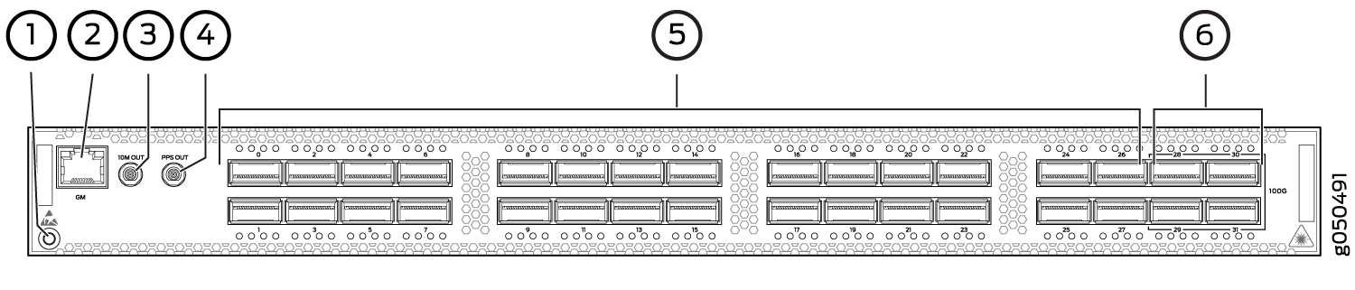
1 — Electrostatic discharge (ESD) terminal | 4 — 1 pulse per second (PPS) output connection |
2 — RJ-45 connection to grandmaster clock | 5 — 28 QSFP+ ports |
3 — Output clock at 10 MHz | 6 — 4 QSFP28 ports |
Network Ports
The QFX5110-32Q device ports (0 through 27) support:
-
40-Gbps QSFP+ transceivers
-
QSFP+ direct attach copper (DAC) cables
-
QSFP+ active optical cables (AOC) (Junos OS Release 18.3R1 and later)
-
40-Gbps QSFP+ to SFP+ DACBO cables (40 Gbps breaks out to 10 Gbps for copper connections on supported ports)
-
40-Gbps AOCBO cables (40 Gbps breaks out to 10 Gbps for fiber connections on supported ports)
The QFX5110-32Q uplink ports (28 through 31) support:
-
100-Gbps QSFP28 transceivers
-
40-Gbps QSFP+ transceivers
-
100-Gbps AOC
-
40-Gbps AOC (Junos OS Release 18.3R1 or later)
-
100-Gbps QSFP28 DAC cables
-
40-Gbps QSFP+ DAC cables
Channelizing Interfaces
Starting with Junos OS Release 18.1R1, default behaviors changed for:
-
System mode—Flexi-pic mode is replaced by non-oversubscribed mode.
-
Auto-sense—The ports auto-sense the transceiver and set the port speed to match.
The Packet Forwarding Engine on the switch is restarted when you issue system mode changes. As a result, you might experience packet loss on the switch.
The following system modes are available on the QFX5110-32Q:
-
Default mode (from Junos OS Release 17.2R1 up to Junos OS Release 18.1R1)
All 32 QSFP+ and QSFP28 ports on the switch are configured for 40-Gigabit Ethernet only. All ports are supported as access or uplink ports, but cannot be channelized.
-
Default mode (Junos OS 18.1R1 and later)
If you connect 40-Gbps optics to all 32 ports, only ports 1 through 18 are available to channelize to 4 independent 10-Gbps speed downstream ports. You can use the remaining ports as dedicated 40 Gbps ports. No ports are disabled.
Depending on the optics installed, you can channelize between 18 to 20 ports.
-
If the system detects a 100-Gbps optic in any one of the QSFP28 ports (28 to 31), the port forms a port group and disables ports 20 to 27. The 40 Gbps QSFP+ ports 0 to 19 can be channelized to 4 independent 10 Gbps speed downstream ports.
-
If the system detects 40 Gbps optics in the QSFP28 ports (28 to 31), you can channelize the 40 Gbps QSFP+ ports 1 to 18 to 4 independent 10 Gbps speed downstream ports. You can use the remaining ports as dedicated 40 Gbps ports. No ports are disabled.
CAUTION:Ports 20 through 27 are not be available for channelization if you have populated the 100 Gbps QSFP28 ports with 100 Gbps optics.
-
-
Flexi-pic mode (from Junos OS Release 17.2R1 up to Junos OS Release 18.1R1):
-
Ports 0 through 19 of the switch are configured for 40-Gigabit Ethernet and can be channelized to 4 independent 10-Gigabit Ethernet ports.
-
Ports 20 though 27 are disabled.
-
Ports 28 through 31 are configured as 100-Gigabit Ethernet.
CAUTION:Take care when changing the channelization mode from Flexi-pic to default. If you have existing ports that are channelized in Flexi-pic mode, remove the channelization from the interface before changing the system mode. Changing the Flexi-pic mode to the default mode with channelized ports causes the ports to go down, log a system log error, and remain down. You must manually remove the channelization configuration on the ports to bring the ports up in default mode. Because there can be a slight loss of data while the FPC reboots, we recommend that you only configure the changes during a maintenance window for this release.
Note:QFX5110-32Q switches that are configured for Flexi-pic mode and upgraded to Junos OS Release 18.1R1 and later come up in default mode.
-
-
Non-oversubscribed mode (Junos OS Release 18.1R1 and later)
Ports 0 through 23 only can be channelized. The remaining ports are disabled. Use this mode to achieve 960 Gbps speeds for either 24 ports of 40 Gigabit Ethernet or 96 ports of 10 Gigabit Ethernet.
Use the request chassis system-mode command to change
the system mode for the switch. If you attempt to channelize a non-supported
port, the configuration is ignored.
Virtual Chassis and Virtual Chassis Fabric
To connect QFX5110 switches as members in a QFX5110 Virtual Chassis, you need a pair of dedicated ports on each switch and cables that link each member in the Virtual Chassis into a ring topology. Each member in the ring has at least one direct Virtual Chassis port (VCP) connection to a upstream and downstream member. QFX5110 switches are recommended in the master, backup, or line card role. You may only mix QFX5100 members with QFX5110 members in a QFX5110 Virtual Chassis; no other QFX Series or EX Series switches are supported. See Connecting QFX5110 and QFX5100 Members in a QFX5110 Virtual Chassis for a a diagram of cabling QFX5110 switches in a ring topology.
To connect a QFX5110 switch as a spine or leaf device in a Virtual Chassis Fabric (VCF), you need a pair of dedicated ports and cables that link each spine device and leaf device in the VCF. All spine devices have at least one direct VCP connection to each leaf device in the VCF. See Connecting QFX5110 in a QFX5110 Virtual Chassis Fabric for a cabling diagram.
QFX5110 Network Port LEDs
The Link/Activity LED configuration for QFX5110-48S uses bi-colored LEDs. The link LED indicates link activity or a fault. See Table 1.
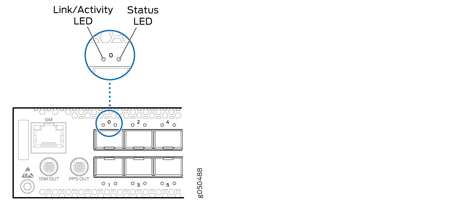
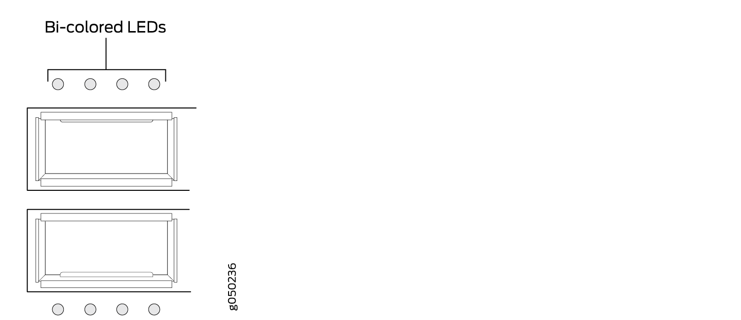
As shown in Table 1 and Table 4 there are four bi-color LEDs for each QSFP+ access port. The first LED indicates link presence and activity, while the remaining LEDs indicate status. Table 2 describes how to interpret the Link/Activity QSFP28 port LEDs, counting from the left-most position.
|
Position |
Color |
State |
Description |
|---|---|---|---|
|
1–4 |
Unlit |
Off |
The port is administratively disabled, there is no power, the link is down, or there is a fault. |
|
1 |
Green |
On steadily |
A link is established (either 100-Gigabit or 40-Gigabit, non-channelized) but there is no link activity. When this LED is on, the LEDs in positions 2 to 4 are off. |
|
Blinking |
A link is established (either 100-Gigabit or 40-Gigabit, non-channelized) and there is link activity. |
||
|
2-4 |
Green |
On steadily |
A 40-Gigabit link is established in channelized mode, but there is no link activity. |
|
Blinking |
A 40-Gigabit link is established in channelized mode, and there is link activity. |
Table 3 describes how to interpret the Link/Activity LEDs on SFP+ ports.
|
LED |
Color |
State |
Description |
|---|---|---|---|
|
Link/Activity |
Unlit |
Off |
The port is administratively disabled, there is no power, the link is down, or there is a fault. |
|
Green |
On steadily |
A link is established, but there is no link activity. |
|
|
Blinking |
A link is established, and there is link activity. |
||
|
Status |
Unlit |
Off |
The link is down or there is a fault. |
|
Green |
On steadily |
A 10-Gigabit Ethernet transceiver is installed in the port and link is established. |
|
|
Green |
Blinking |
A 1-Gigabit Ethernet transceiver is installed in the port and the link is established. |
|
QFX5110-32Q |
QSFP28 and QSFP+ |
Link and ActivityStatus |
|