QFX5110 Management Panel
QFX5110 Management Panel Description
The management panel of the QFX5110 is found on the field-replaceable unit (FRU) end of the switch, as shown in Figure 1. See Figure 2 for FRUs and management panel detail.
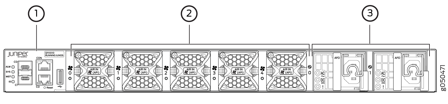
1 — Management panel | 3 — Power supply units |
2 — Fan modules |
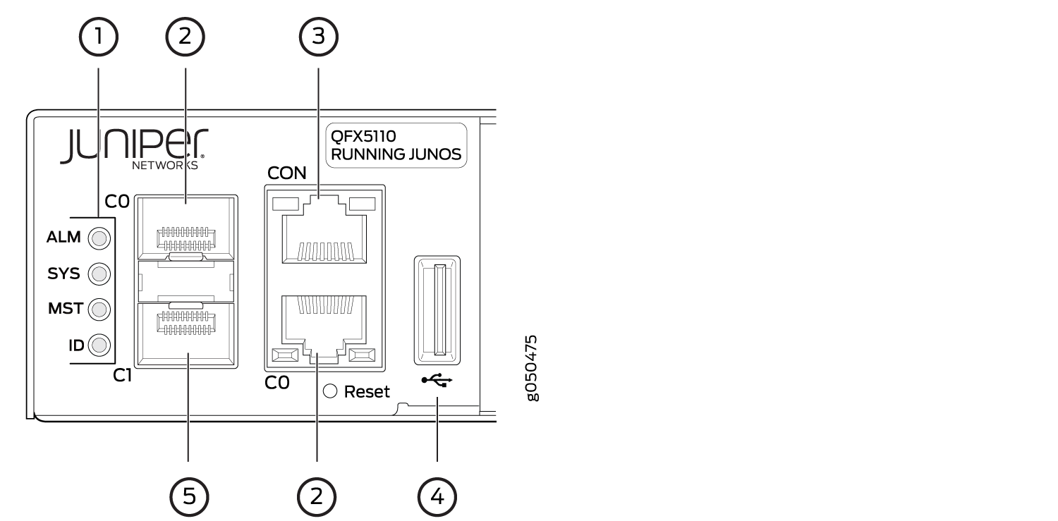
1 — Status LEDs | 4 — USB port |
2 — em0–RJ-45 (1000BASE-T) management Ethernet port (C0)and an additional SFP management Ethernet port (second C0) | 5 — em1–SFP management Ethernet port (C1)Cage (socket for either 1-GbE copper SFP or fiber SFP) |
3 — RJ-45 console port (CON) |
The management panel consists of the following components:
-
Status LEDs, see QFX5110 Chassis Status LEDs.
-
Switch product number
-
Management ports C0 and C1, see QFX5110 Management Port LEDs.
-
C0–Use the RJ-45 connectors for 10/100/1000BASE-T or to cable a virtual management Ethernet (VME) interface for spine members in a VCF. See Connect a Device to a Network for Out-of-Band Management.
Note:If both C0 ports are cabled, the copper C0 has priority over the fiber C0.
-
C1–Use the SFP connector for 1000BASE-X.
-
-
USB port for image updates
-
Console port (RJ-45) to support RS-232 serial ports. The LEDs above the port indicate status and link.
QFX5110 Management Port LEDs
The management ports (labeled C0 for 10/100/1000BASE-T and C1 for 10/100/1000BASE-T and SFP 1000BASE-X connections) on a QFX5110 switch have two LEDs that indicate link status and link activity (see Figure 3). The left LED indicates status; the right LED indicates link/activity.
1 — Status LEDs | 4 — USB port |
2 — em0–RJ-45 (10/100/1000BASE-T) management Ethernet port (C0) | 5 — em1–SFP management Ethernet port (C1) cage (socket for either 10/100/1000BASE-T RJ-45 SFP or 1-GbE fiber SFP) |
3 — RJ-45 console port (CON)) |
Table 1 describes the management port LEDs.
|
LED |
Color |
State |
Description |
|---|---|---|---|
|
Link/Activity |
Unlit |
Off |
No link is established, there is a fault, or the link is down. |
|
Green |
On steadily |
A link is established, but there is no link activity. |
|
|
Blinking or flickering |
A link is established, and there is link activity. |
||
|
Status |
Unlit |
Off |
Either the port speed is 10 M or the link is down. |
|
Green |
On steadily |
The port speed is 1000 M. |
|
|
Amber |
On steadily |
The port speed is 100 M. |
QFX5110 Chassis Status LEDs
The QFX5110 switch series has four status LEDs on the FRU side of the chassis, next to the management ports (see Figure 4).
1 — Status LEDs | 4 — USB port |
2 — em0–RJ-45 (10/100/1000 BASE-T) management Ethernet port (C0) | 5 — em1–SFP management Ethernet port (C1) cage (socket for either 10/100/1000 BASE-T RJ-45 SFP or 1-GbE fiber SFP) |
3 — RJ-45 console port (CON) |
Table 2 describes
the chassis status LEDs on a QFX5110, their colors and states, and
the status they indicate. You can view the colors of the three LEDs
remotely through the CLI by issuing the operational mode command show chassis lcd.
|
Name |
Color |
State |
Description |
|---|---|---|---|
|
ALM–Alarm or beacon |
Unlit |
Off |
The switch is halted or there is no alarm. |
|
Red |
On steadily |
A major hardware fault has occurred, such as a temperature alarm or power failure, and the switch has halted. Power off the QFX5110 by setting the AC power source outlet to the off (O) position, or unplugging the AC power cords. Correct any voltage or site temperature issues, and allow the switch to cool down. Power on the QFX5110 and monitor the power supply and fan LEDs to help determine where the error is occurring. |
|
|
Amber |
On steadily |
A minor, non-critical alarm has occurred, such as a software error. Power off the QFX5110 by setting the AC power source outlet to the off (O) position, or unplugging the AC power cords. Power on the QFX5110 and monitor the status LEDs to ensure that Junos OS boots properly. |
|
|
SYS–System |
Unlit |
Off |
The switch is powered off or halted. |
|
Green |
On steadily |
Junos OS for QFX Series is loaded on the switch. |
|
|
Green |
Blinking |
The switch is participating as:
|
|
|
MST–Primary in a QFX Virtual Chassis or Routing Engine Primary in a VCF |
Unlit |
Off |
The switch is a line card member in a QFX Virtual Chassis. |
|
Green |
On steadily |
The switch is one of the following:
|
|
|
Green |
Blinking |
The switch is the backup primary in a QFX Virtual Chassis or the backup routing engine in a VCF. |
|
|
ID–Identification |
Unlit |
Off |
The beacon feature is not enabled on the switch. This
feature is enabled using the |
|
Blue |
Blinking |
The beacon feature is enabled on the switch. This feature
is enabled using the |