Maintaining QFX10002 Power Supplies
Use the following procedures to replace a power supply in a QFX10002:
Removing a Power Supply from a QFX10002
Before you remove a power supply from a QFX10002, ensure that you have taken the necessary precautions to prevent electrostatic discharge (ESD) damage (see Prevention of Electrostatic Discharge Damage).
Ensure that you have the following parts and tools available to remove a power supply from a QFX10002:
-
ESD grounding strap
-
Antistatic bag or an antistatic mat
-
Phillips (+) screwdriver, number 2 (DC power supply)
If you are removing a redundant power supply and do not plan to replace it with another immediately, have a power supply cover for the opening.
The power supplies in a QFX10002 are hot-removable and hot-insertable field-replaceable units (FRUs): you can remove and replace them without powering off the switch or disrupting switch functions after the power cord is disconnected.
Replace the power supply with a new power supply within 1 minute of removal to prevent chassis overheating.
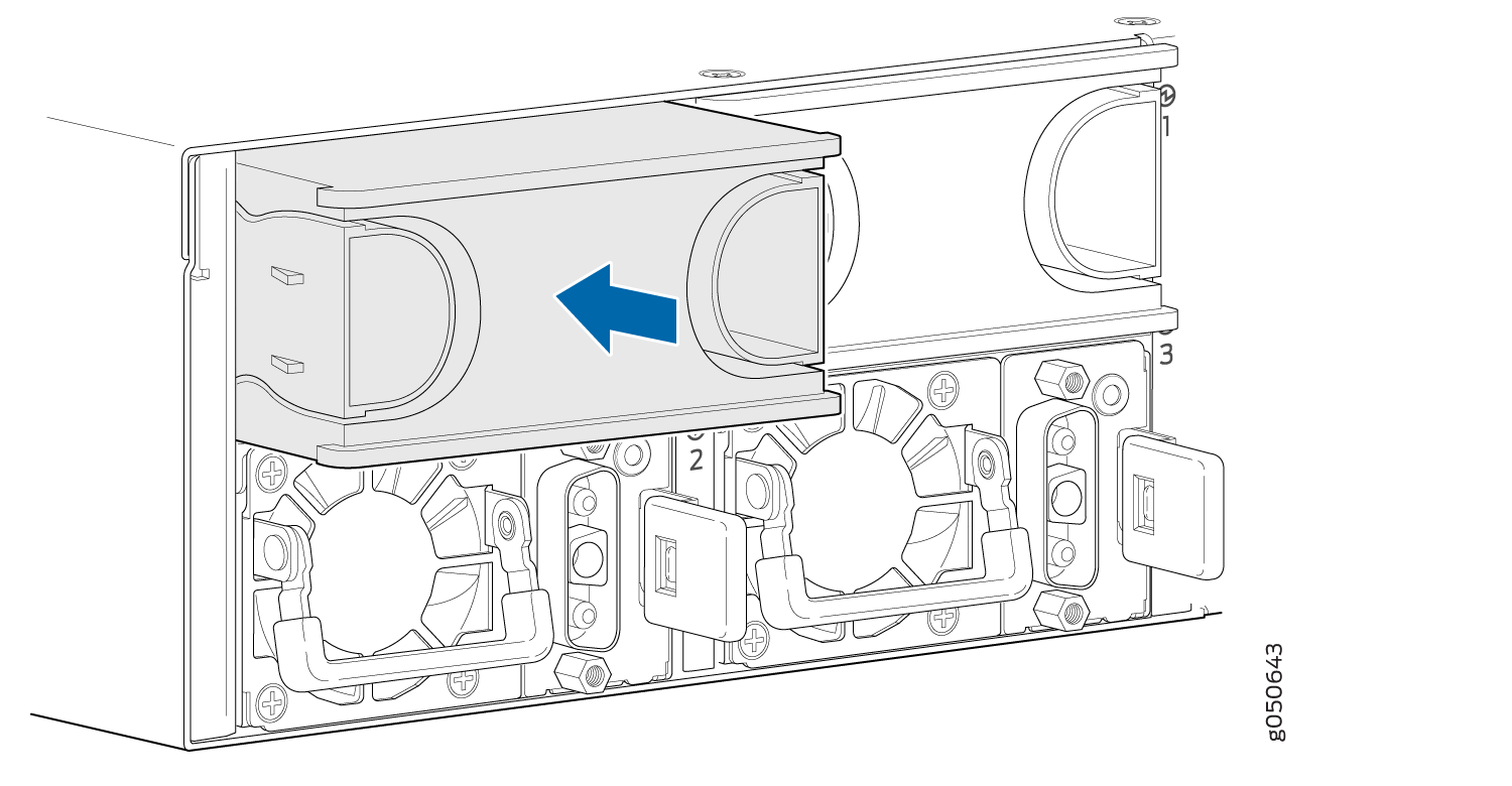
To remove a power supply from a QFX10002 (see Figure 1):
-
Grasp the power supply handle and pull firmly to slide
the power supply halfway out of the chassis.
Figure 1: Removing a Power Supply from a QFX10002-72Q

-
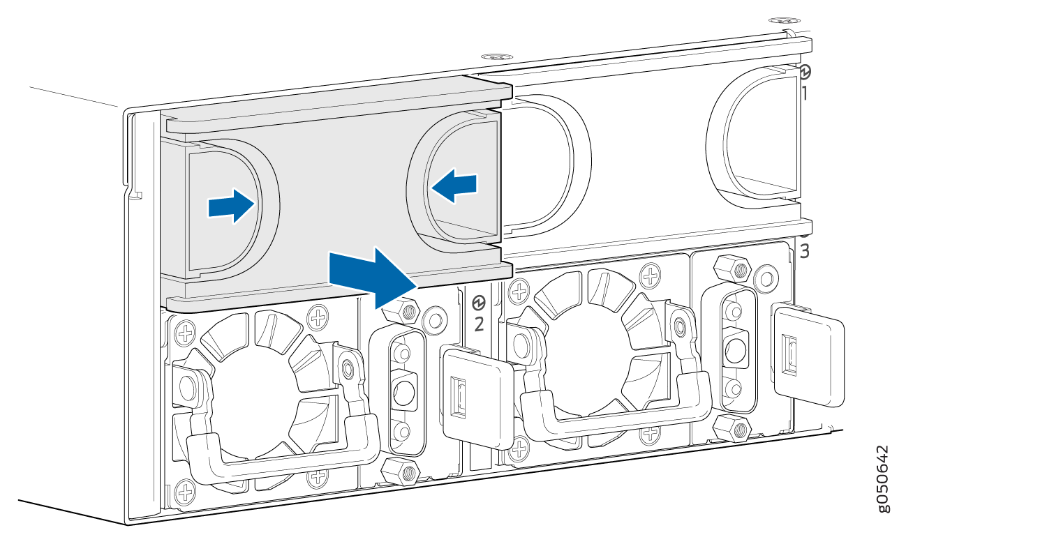
Either replace with another power supply or insert a PSU
blank cover (QFX10002-PWR-BLNK).
Figure 2: Inserting a Power Supply Blank Cover
Installing a Power Supply in a QFX10002
-
Before you install a power supply in a QFX10002, ensure that you have taken the necessary precautions to prevent electrostatic discharge (ESD) damage (see Prevention of Electrostatic Discharge Damage).
-
Ensure that the airflow direction of the power supply is the same as the chassis. Labels on the power supply handle indicate the direction of airflow. See QFX10002 Cooling System.
The power supplies in a QFX10002 are hot-removable and hot-insertable field-replaceable units (FRUs): you can remove and replace them without powering off the switch or disrupting switch functions.
To install a power supply in a QFX10002 (see Figure 4):
-
If the power supply is being installed in an empty slot,
remove the blank cover by squeezing the finger holds and pulling the
cover straight out.
Figure 3: Removing a Power Supply Blank Cover

Each power supply must be connected to a dedicated power source outlet.
If you have a Juniper Care service contract, register any addition, change, or upgrade of hardware components at https://www.juniper.net/customers/support/tools/updateinstallbase/ . Failure to do so can result in significant delays if you need replacement parts. This note does not apply if you replace existing components with the same type of component.