QFX10002 Cooling System
QFX10002 Cooling System and Airflow
The cooling system in a QFX10002 consists of three 80-W fan modules in a fan tray and two counter-rotating fans housed in each of the power supplies.
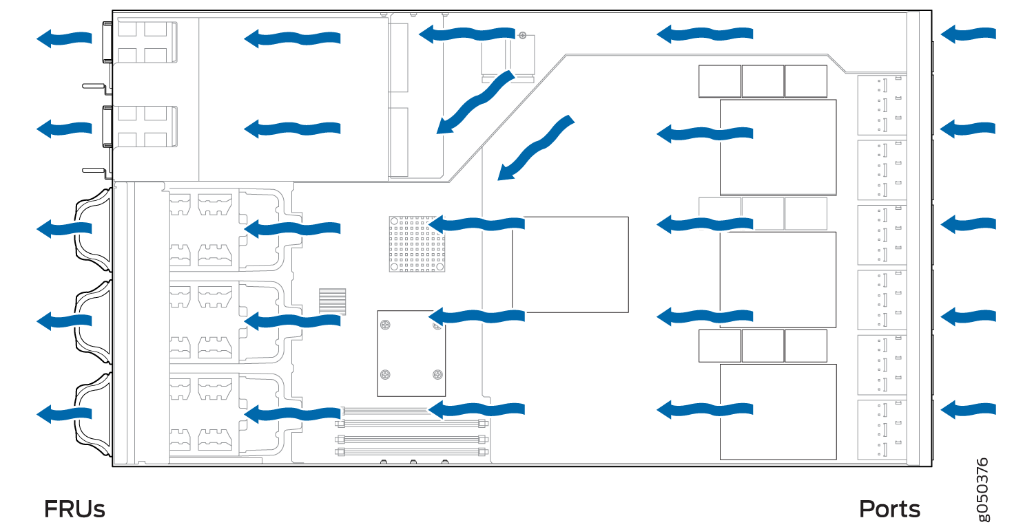
The QFX10002 brings air into the vents in the port panel and exhausts warmed air through the field-replaceable units (FRU) panel. This type of airflow is known as airflow out or port-to-FRU airflow.
This topic describes:
Fan Modules
The fan modules in a QFX10002 are hot-removable and hot-insertable FRUs designed for port-to-FRU airflow. The fan modules numbered 0 through 2 are installed in the fan tray located next to the power supplies. Each fan module slot has a fan icon next to it.
Figure 1 shows the 2-U fan module for the QFX10002 models.
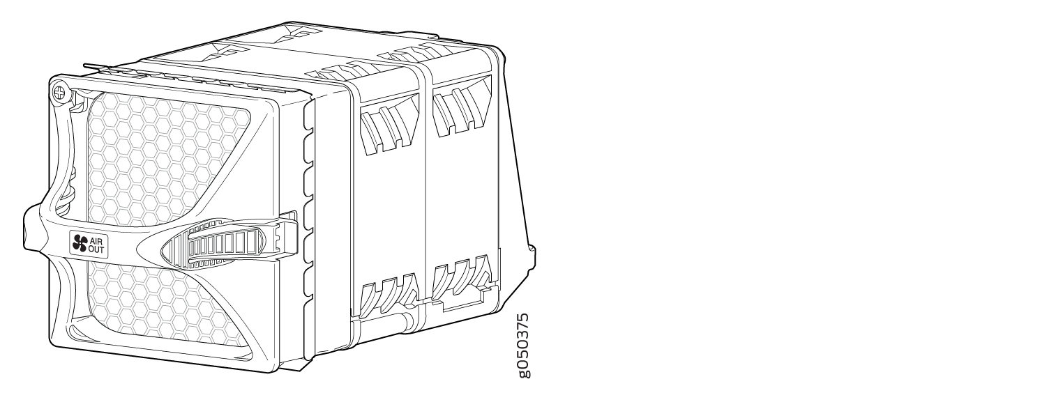
You remove and replace a fan module from the FRU end of the chassis. The switch continues to operate for a limited period of time (30 seconds) during the replacement of the fan module without thermal shutdown.
All fan modules must be installed for optimal operation of the switch.
Table 1 lists the fan module details.
|
Fan Module |
Airflow Diagram |
Label on the Fan Module |
Color of Fan Module Handle |
Direction of Airflow in the Fan Module |
Power Supplies |
|---|---|---|---|---|---|
|
QFX10002-FAN |
AIR OUT |
Juniper Gold |
Port-to-FRU airflow is where air enters on the end with the ports and exits on the end with fans (also known as airflow out). |
All models only use power supplies that have gold-colored handles with AIR OUT labels. |
In data center deployments, position the switch in such a manner that the AIR OUT labels on switch components are next to the hot aisle. Figure 2 shows the airflow through the chassis.
Fan Module Status
You can check the status of fan modules through the show
system alarms command or show chassis fan commands
or by looking at the LEDs next to each fan module. For example:
user@device> show chassis fan
Item                      Status   RPM     Measurement
      Tray 0 Fan 0              Absent
      Tray 0 Fan 1              Absent
      Tray 1 Fan 0              OK       5000    Spinning at normal speed
      Tray 1 Fan 1              OK       4400    Spinning at normal speed
      Tray 2 Fan 0              OK       5000    Spinning at normal speed
      Tray 2 Fan 1              OK       4400    Spinning at normal speed
Each switch has a status LED (labeled ST) for each fan module on the left side of the corresponding fan module slot. It indicates the status of all the fan modules. Table 2 describes the status LED on the fan module in a QFX10002.
|
LED State |
Description |
|---|---|
|
Solid Green |
Indicates the individual fan module is present. After the hardware senses the fan module, software ensures the airflow is consistent with the other fan modules and that it is functioning correctly. |
|
Solid Amber |
Indicates one of the following:
|
Under normal operating conditions, the fan modules operate at a moderate speed. Temperature sensors in the chassis monitor the temperature within the chassis.
The system raises an alarm if a fan module fails or if the ambient temperature inside the chassis rises above the acceptable range. If the temperature inside the chassis rises above the threshold temperature, the system shuts down automatically.
See Also
QFX10002 Fan Module LED
Figure 3 shows the location of the LED next to the QFX10002 fan module.

1 — Fan LED |
Use Table 3 to interpret the state of the fan module LED.
|
Name |
Color |
State |
Description |
|---|---|---|---|
|
Fan |
Green |
On steadily |
The fan module is operating normally. The system has verified that the module is engaged, and that the fan is operating correctly. |
|
Amber |
On steadily |
An error has been detected in the fan module. Replace the fan module as soon as possible. Either the fan has failed or it is seated incorrectly. To maintain proper airflow through the chassis, leave the fan module installed in the chassis until you are ready to replace it. |