QFX10002 System Overview
The Juniper Networks QFX10002 fixed configuration switch builds a strong underlay foundation for flexible, high-performance, standards-based fabrics and routing that improve network reliability and agility. As part of the QFX10000 line of switches, the QFX10002 models provide the flexibility of 10-Gbps, 40-Gbps, and 100-Gbps port speeds in a 2 U fixed configuration. For more information, see the following topics:
QFX10002 Switch Description
The Juniper Networks QFX10002 is a fixed configuration switch that offers a variety of port densities and network port configurations. This topic covers:
- Benefits of the QFX10002 Switch
- QFX10002 Models
- System Architecture
- Cooling and Power
- System Software
Benefits of the QFX10002 Switch
-
Combats application latency by using a deep buffer with hybrid memory cube (HMC) technology to absorb network traffic spikes. Deep buffers are important at the edge of data center networks where typically there is a speed mismatch between WAN-facing interfaces and data center-facing interfaces.
-
Operates as a universal platform that can be positioned in multiples roles –data center, data center interconnect, or data center edge, as well as campus and routing use cases because of its high logical scale.
-
Enables cloud providers to collapse multiple layer in the network (spine and data center interconnect) that offer capital and operational expenditure savings.
-
Saves on power with an optimized power profile per 100 Gigabit Ethernet.
QFX10002 Models
The QFX10002 line of switches are deep-buffer fixed-chassis switches in a 2 U form factor for fixed core and spine deployments. All models of the QFX10002 support port densities of 10 Gigabit Ethernet, 40 Gigabit Ethernet and 100 Gigabit Ethernet. In addition, all switches are available with either an AC or DC power supply and with port to field replaceable unit (FRU) cooling. This type of cooling is also known as airflow out (AFO) or front-to-back cooling. The QFX10002 is available in three port configurations:
-
QFX10002-36Q
-
QFX10002-72Q
-
QFX10002-60C
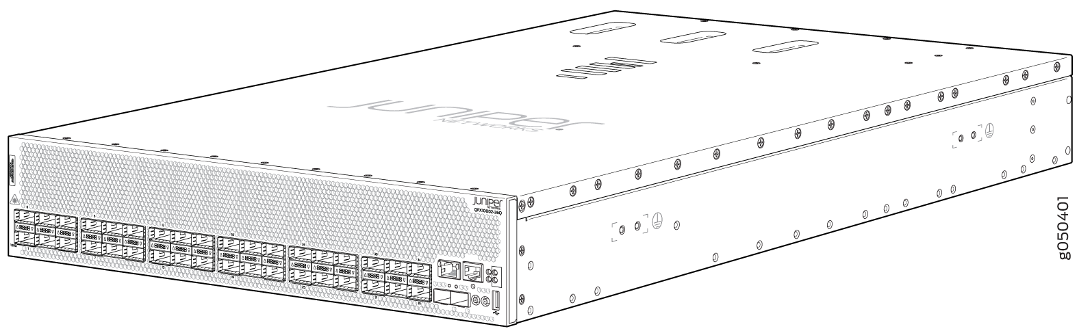
The QFX10002-36Q offers 36 40-Gbps capable quad small-form factor pluggable (QSFP+) ports. Of the 36 ports, 12 ports (0 through 35 every third port) supports 100-Gbps capable Quad Small Form-Factor Pluggable 28 (QSFP28) optical transceiver. Using the break-out cables any of the 36 40-Gbps ports can be configured to operate as four 10-Gigabit Ethernet interfaces. The QFX10002-36Q has up to 2.88 terabits per second (Tbps) of throughput and 1 billion packets per second (Bpps) of forwarding capacity. This model ships with redundant 1600 W AC or DC power supplies and three fan modules. See Figure 1.
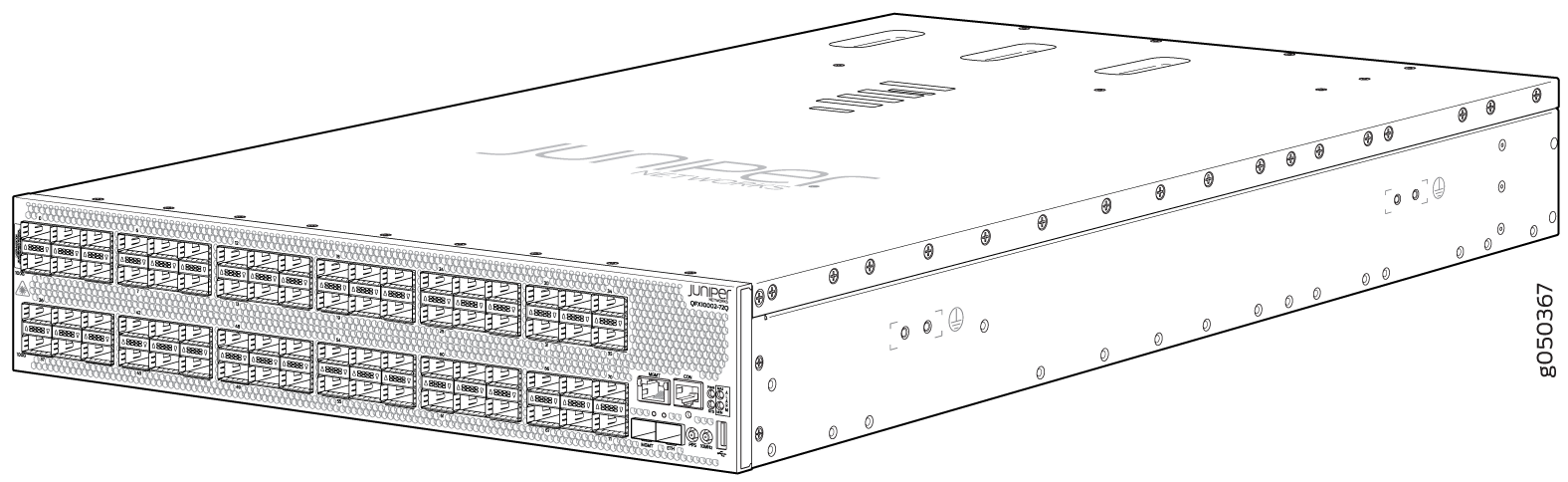
The QFX10002-72Q offers 72 40-Gbps capable quad small-form factor pluggable (QSFP+) ports. Of the 72 ports, 24 ports (0 through 71 every third port) supports 100-Gbps capable Quad Small Form-Factor Pluggable 28 (QSFP28) optical transceiver. Using the break-out cables any of the 72 40-Gbps ports can be configured to operate as four 10-Gigabit Ethernet interfaces. It has up to 5.76 Tbps of throughput and 2 Bpps of forwarding capacity. This model ships with 4 redundant 1600 W AC or DC power supplies and three fan modules. See Figure 2.
The QFX10002-60C offers flexible configuration of the 60 QSFP28 ports. Each port can be configured as either 100 Gbps, 40 Gbps, or 4 by 10 Gbps. It has up to 12 Tbps of throughput and 4 Bpps of forwarding capacity. The QFX10002-60C ships with four 1600 W AC or DC power supplies and three fan modules. See Figure 3.
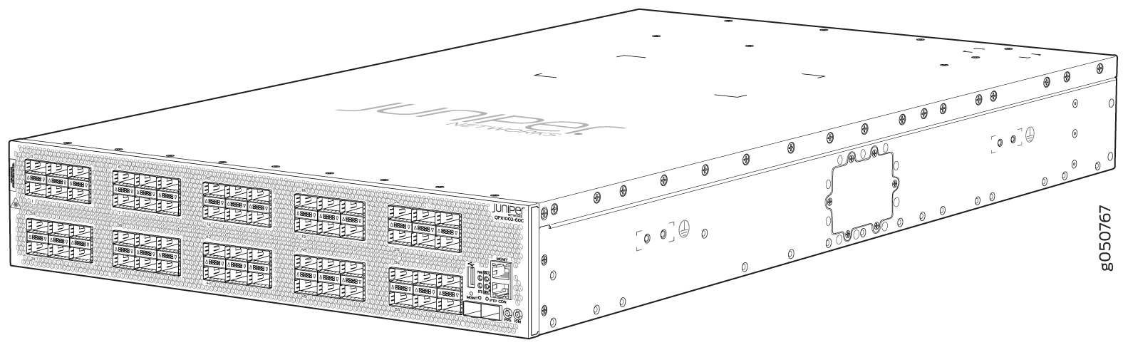
Table 1 lists the ordering numbers for QFX10002 devices. See Figure 1 through Figure 3 for illustrations of the models.
|
Product Numbers |
Ports |
Power Supply |
|---|---|---|
|
QFX10002-72Q |
72 QSFP+ |
AC |
|
QFX10002-72Q-DC |
72 QSFP+ |
DC |
|
QFX10002-60C |
60 QSFP28 |
AC |
|
QFX10002-60C-DC |
60 QSFP28 |
DC |
|
QFX10002-36Q |
36 QSFP+ |
AC |
|
QFX10002-36Q-DC |
36 QSFP+ |
DC |
The QFX10002 models feature PHY-less interfaces to save on power and to lower latency. The ports on all models support quad small-form factor pluggable (QSFP+) transceivers and the 28-Gbps QSFP+ Pluggable Solution (QSFP28) transceivers. The interfaces on a QFX10002 can be configured to support 10-Gbps, 40-Gbps, and 100-Gbps port speeds. See Table 2.
|
QFX10002-36Q |
QFX10002-60C |
QFX10002-72Q |
|
|---|---|---|---|
|
10 Gigabit Ethernet |
144 |
192 |
288 |
|
40 Gigabit Ethernet |
36 |
60 |
72 |
|
100 Gigabit Ethernet |
12 |
60 |
24 |
System Architecture
The system architecture cleanly separates control operations from packet forwarding operations. This design eliminates processing and traffic bottlenecks, permitting the QFX10002 to achieve high performance.
-
Control operations are performed by the Routing Engine, which runs the Juniper Networks Junos operating system (Junos OS). The Routing Engine handles routing protocols, traffic engineering, policy, policing, monitoring, and configuration management. Junos OS is installed on the QFX10002 internal solid-state drives (SSDs). QFX10002-36Q and QFX10002-72Q have 2 x 25-GB SSD and the QFX10002-60C has 2 x 64-GB SSDs. The Routing Engine has a 2.5-GHz quad core Intel CPU and has 16 GB of SDRAM on the QFX10002-36Q and QFX10002-72Q. There is 32 GB of SDRAM on the QX10002-60C.
-
Forwarding operations are performed by the Packet Forwarding Engines, which include custom ASICs designed by Juniper Networks. The Q5 ASICs enable the QFX10002 to provide up to 2.88 terabits per second (Tbps) of throughput on the QFX10002-36Q, 5.76 Tbps on the QFX10002-72Q and 12 Tbps on the QFX10002-60C. The Q5 ASICs are connected to Hybrid Memory Cubes (HMCs). These high-efficiency memory modules provide packet buffering, virtual output queue (VOQ) memory, and improved logical system scale.
Cooling and Power
The cooling system in a QFX10002 consists of three 80-W fan modules that operate at 150 cubic feet per minute (CFM) at full speed as well as fans housed in the power supplies. Each fan modules has dual counter-rotating fans. These fan modules can be hot-swapped and hot-inserted, meaning that– you do not need to power off the switch or disrupt the switching function to replace a module.
in the QFX10002 cooling system, cool air enters through the vents in the port panel and hot air exhausts through the field-replaceable unit (FRU) panel. This type of airflow is known as airflow out or port-to-FRU airflow.
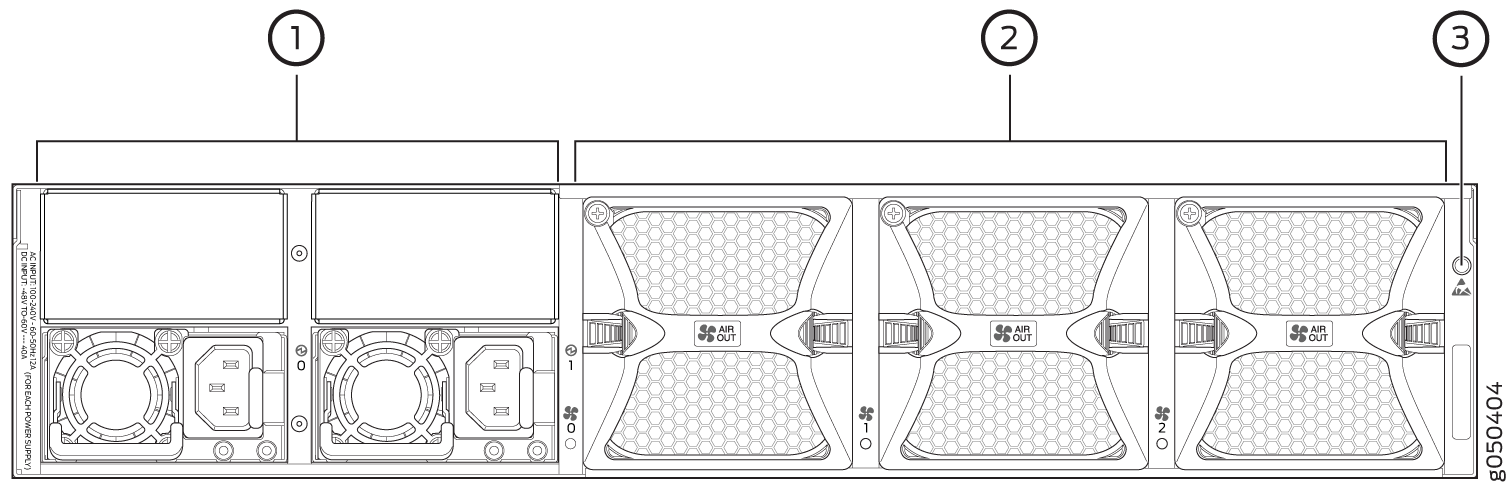
The four AC or DC 1600-W power supplies are installed by the factory in the QFX10002-72Q and QFX10002-60C; two power supplies are installed in the QFX10002-36Q. See Figure 4 for an example of the QFX10002-72Q FRU panel. Each power supply provides 12 VDC output with a standby voltage of 12-VDC.The AC or DC power supplies in a QFX10002 are hot-removable and hot-insertable FRUs.
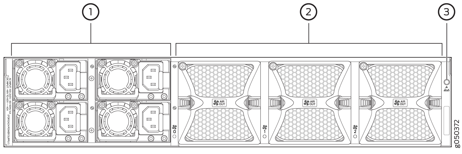
1 — Power supply modules (4) for QFX10002-72Q and QFX10002-60C. Two power supply modules are provided for QFX10002-36Q. | 3 — ESD point |
2 — Fan modules (3) |
Mixing different types (AC and DC) of power supplies in the same chassis is not supported.
The power supply bays on the QFX10002-72Q and QFX10002-36Q are numbered horizontally from the top left to the bottom right. The QFX10002-60C power supply bays are numbered vertically from the top left to the bottom right, which matches CLI output.
System Software
QFX Series devices use the Junos operating system (OS), which provides Layer 2 and Layer 3 switching, routing, and security services. Junos OS is installed on a QFX10002 switch’s 25-gigabyte (GB) internal NAND solid state flash drive. The same Junos OS code base that runs on QFX10002 switches also runs on all Juniper Networks EX Series switches, and M Series, MX Series, and T Series routers.
For more information about which features are supported on QFX Series devices, see Feature Tracker.
You manage the switch using the Junos OS command-line interface (CLI), which is accessible through the console and out-of-band management ports on the device.
QFX10002 Hardware Component Overview
The QFX10002 supports the components in listed in alphabetic order. See QFX10002 Chassis Physical Specifications for the dimensions and weight of the QFX10002 models.
Component |
Spare Juniper Model Number |
CLI Output |
|---|---|---|
Chassis |
QFX10002-72Q-CHAS-S JNP10002-60C QFX10002-36Q-CHAS-S |
|
Fan module |
QFX10002-FAN-S JNP10002-FAN1 |
|
Power supplies |
JPSU-1600W-AC-AFO JPSU-1600W-DC-AFO |
|
QFX10002 Component Redundancy
The following hardware components provide redundancy on QFX10002 models:
Power supplies
As shown in Table 4, the QFX10002-72Q and QFX10002-60C can operate with a single DC input power supply or a single AC input power supply for 220VAC operation. A minimum of two AC power supplies are required to operate the QFX10002-72Q and QFX10002-60C at 110VAC. The QFX1002-36Q can operate with a single DC input power supply or it can operate with a single AC power supply at 110VAC and 220VAC.
CAUTION:When running the switch in non-redundant mode, install a power supply cover (QFX10002-PWR-BLNK) in any unused power bays for safety, cooling, and emissions control.
The recommended configuration is to run the switch with twice as much power as needed, also called 2N, for full power redundancy. To provide additional power for switch redundancy or feed-redundancy, see Table 4.
Table 4: Available Power Redundancy Options Model
Power
Non-redundant (N)
2N or Dual Feed
QFX10002-72Q
220 VAC
1
2
For power feed redundancy, connect power source feed A to power supplies 0 or 1 and connect power source feed B to power supplies 2 or 3. The remaining slots should be covered with a power supply blank cover.
110 VAC
2
4
For power feed redundancy, connect power source feed A to power supplies 0 and 1 and connect power source feed B to power supplies 2 and 3.
QFX10002-72Q-DC
DC
1
2
For power feed redundancy, connect power source feed A to power supplies 0 or 1 and connect power source feed B to power supplies 2 or 3. The remaining slots should be covered with a power supply blank cover.
QFX10002-60C
220 VAC
1
2
For power feed redundancy, connect power source feed A to power supplies 0 or 1 and connect power source feed B to power supplies 2 or 3. The remaining slots should be covered with a power supply cover.
110 VAC
2
4
For power feed redundancy, connect power source feed A to power supplies 0 and 1 and connect power source feed B to power supplies 2 and 3.
QFX10002-60C-DC
DC
1
2
For power feed redundancy, connect power source feed A to power supplies 0 or 1 and connect power source feed B to power supplies 2 or 3. The remaining slots should be covered with a power supply blank cover.
QFX10002-36Q
220 VAC
1
2
For power feed redundancy, connect power source feed A to power supplies 0 or 1 and connect power source feed B to power supplies 2 or 3. The remaining slots should be covered with a power supply cover.
110 VAC
1
2
For power feed redundancy, connect power source feed A to power supplies 0 or 1 and connect power source feed B to power supplies 2 or 3. The remaining slots should be covered with a power supply cover.
QFX10002-36Q-DC
DC
1
2
For power feed redundancy, connect power source feed A to power supplies 0 or 1 and connect power source feed B to power supplies 2 or 3. The remaining slots should be covered with a power supply cover.
Cooling system—All models of the QFX10002 have three fan modules. Each fan module is a redundant unit containing two fans. If a fan module fails and is unable to keep the QFX10002 within the desired temperature thresholds, chassis alarms occur and the QFX10002 device might shut down.
QFX10002 Field-Replaceable Units
Field-replaceable units (FRUs) are components that you can replace at your site. The QFX10002 FRUs are hot-removable and hot-insertable: you can remove and replace them without powering off the switch or disrupting the switching function.
Replace a failed fan module with a new fan module within one minute of removal to prevent chassis overheating.
Table 5 lists the FRUs for the QFX10002-72Q and actions to take before removing them.
|
FRU |
Required Action |
|---|---|
|
Power supplies: QFX10002-72Q and QFX10002-60C (4), QFX10002-36Q (2) |
Remove the power cord for the power supply unit. |
|
Fan modules (3) |
None. |
|
Optical transceivers |
None. We recommend that you disable the interface using the set interfaces interface-name disable command before you remove the transceiver. See Disconnect a Fiber-Optic Cable. |
See Figure 5 for an example of the FRU panel on a QFX10002-36Q.
1 — Power supplies (2) | 3 — ESD point |
2 — Fan modules (3) |
If you have a Juniper Care service contract, register any addition, change, or upgrade of hardware components at https://www.juniper.net/customers/support/tools/updateinstallbase/ . Failure to do so can result in significant delays if you need replacement parts. This note does not apply if you replace existing components with the same type of component.