QFX10002 Port Panels
QFX10002-36Q Port Panel
The port panel of the QFX10002-36Q consists of 36 quad small-form factor pluggable plus (QSFP+) ports that support 10-Gbps, 40-Gbps and 100-Gbps port speeds. Of these 36 ports, 12 ports accept QSFP28 transceivers, which are dual speed 40- or 100-Gigabit Ethernet optical transceivers.
This topic describes:
Overview
Any of the 36 ports 0 through 35 can be configured as either uplink or network ports. See Figure 1.
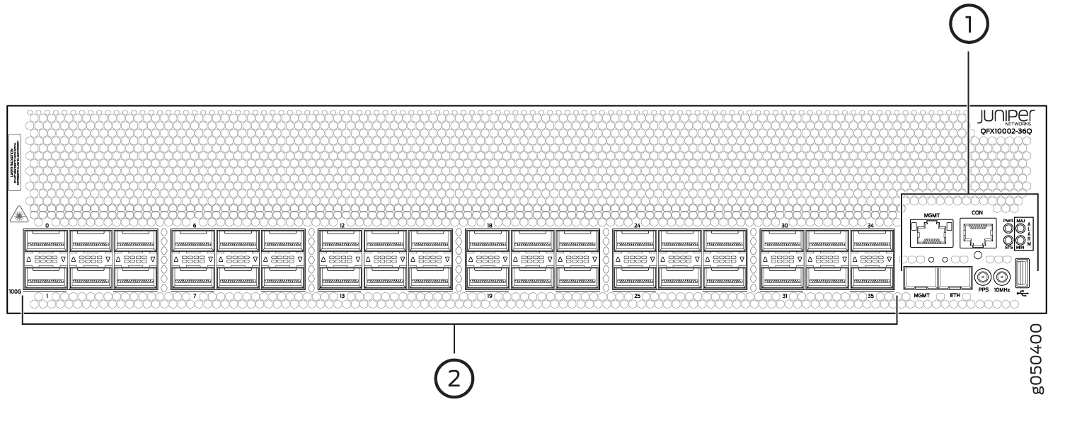
1 — Management panel | 2 — Port panel with QSFP+ network interface or uplink ports (36) |
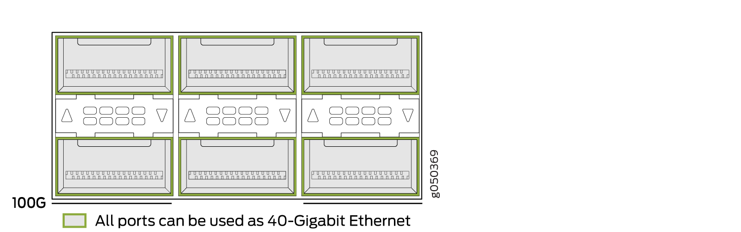
The default configuration is independent 40-Gigabit Ethernet for all 36 ports. For 100-Gbps or 10-Gbps channelization operation, the ports operate within port groups. Every three ports compose a port group. See Table 1 and Figure 2 through Figure 5.
Per Port Group |
Per Switch |
|---|---|
1 x100 Gbps |
12 x 100 Gbps |
3 x 40 Gbps |
36 x 40 Gbps |
12 x 10 Gbps |
144 x 10 Gbps |
The second and sixth port in each 6XQSFP+ socket can be configured to support:
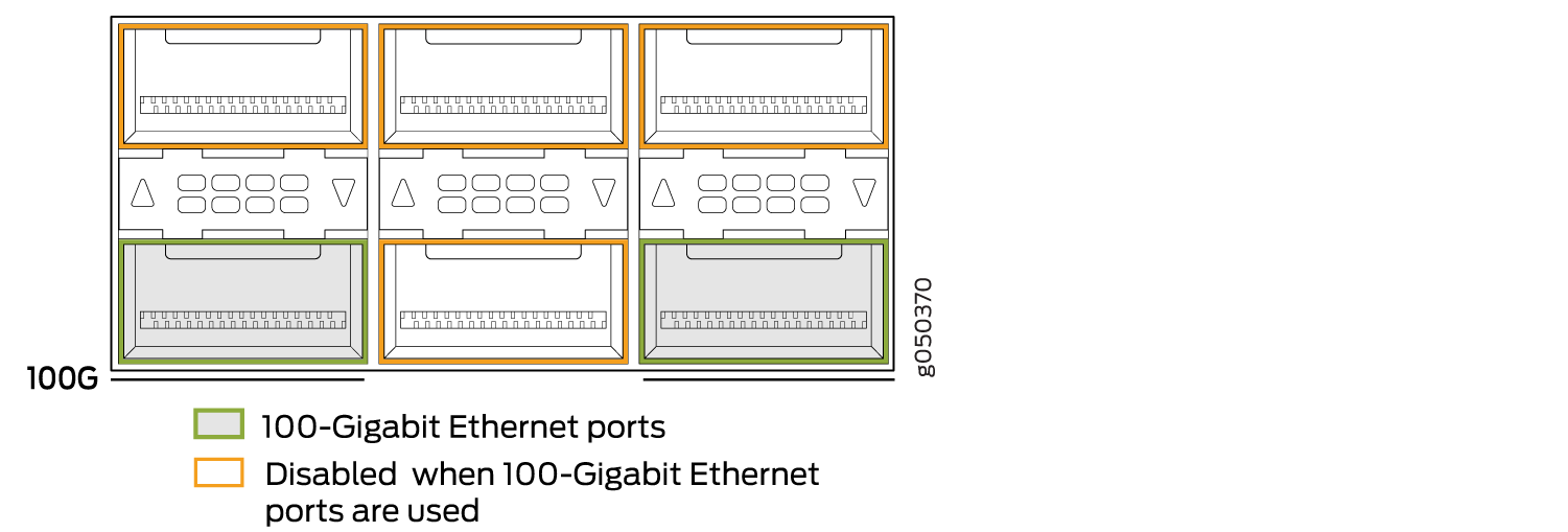
100-Gigabit Ethernet using 28-Gbps QSFP28 optical transceivers and 100-Gbps active optical cables (AOCs). When a QSFP28 transceiver is inserted into the ports marked with a fine black line underneath the socket and the port is configured for 100-Gigabit Ethernet, the two adjacent ports are disabled and the QSFP28 is enabled for 100-Gigabit Ethernet.
40-Gigabit Ethernet using QSFP+ optical transceivers or 40-Gbps direct attach copper (DAC) cables.
10-Gigabit Ethernet using DAC breakout cables (DACBO). When configured for channelization, a breakout cable converts the 40-Gigabit Ethernet port into 4 independent 10-Gigabit Ethernet ports. The two adjacent QSFP+ ports in the port group are also configured for channelization at the same time. You cannot configure a single port for channelization.
Network Ports
Each of the 12 QSFP28 ports support:
100-Gigabit Ethernet QSFP28 transceivers
100-Gigabit Ethernet active optical cables (AOCs)
40-Gigabit Ethernet QSFP+ transceivers
40-Gigabit Ethernet QSFP+ DAC cables
40-Gigabit Ethernet QSFP+ to 10-Gigabit Ethernet SFP+ direct attach copper breakout (DACBO) cables
The remaining ports support:
40-Gigabit Ethernet QSFP+ transceivers
40-Gigabit Ethernet QSFP+ DAC cables
40-Gigabit Ethernet QSFP+ to 10-Gigabit Ethernet SFP+ DACBO cables
10-Gigabit Ethernet SFP+ transceivers
10-Gigabit Ethernet DAC cables
100-Gbps Operation and Configuration
Every second and sixth port in a 6XQSFP cage on a QFX10002 supports
100-Gigabit Ethernet using QSFP28 transceivers. These 100-Gigabit
Ethernet ports work either as 100-Gigabit Ethernet or as 40-Gigabit Ethernet,
but are recognized as 40-Gigabit Ethernet by default. See Figure 2 for a close up view of a 6XQSFP+
cage. The 100-Gigabit Ethernet are designated by a fine black line
underneath the port. See Figure 3.
When a 40-Gigabit Ethernet transceiver is inserted into a 100-Gigabit
Ethernet port, the port recognizes the 40-Gigabit Ethernet port
speed. However, when an 100-Gigabit Ethernet transceiver is inserted
into the port, the transceiver is not automatically recognized and
is not seen in the output of the show chassis hardware command.
To enable 100-Gigabit Ethernet on the marked ports, use the set
chassis fpc command. For example, to enable port 11 for 100
Gbps speeds:
[edit]
user@switch#
set chassis fpc 0 pic 0 port 11 speed 100g
The port then recognizes the 100-Gigabit Ethernet speed and disables two adjacent 40-Gigabit Ethernet ports. See Figure 4.
Figure 2 shows one of the six 6XQSFP+ cages on a QFX10002-36Q.
40-Gbps Channelization
The 40-Gigabit Ethernet ports can operate independently or be bundled with the next
two consecutive ports and channelized into twelve 10-Gigabit Ethernet ports as a
port group. Like 100-Gigabit channelization, only the first and fourth port in each
6XQSFP cage are available to channelize a port group (see Figure 5. The port group must
be configured using the set chassis fpc pic port channel-speed
command. For example, to channelize the first switch port, use the set
chassis fpc 0 pic 0 port
0 channel-speed 10g command.
You cannot channelize an individual port. Channelizing configures all three ports in the port range to four independent 10-Gigabit Ethernet.
Port Mapping
Table 2 shows the available combinations for the ports. Most 100-Gigabit Ethernet transceiver ports are used as uplinks. On the QFX10002 device, the ports are enabled by default and the default config adds the ports to the default VLAN.
|
Port Number |
4X10 Gigabit Channelized Port |
4X10 Gigabit Channelized Port Group |
40 Gigabit Ethernet |
100 Gigabit Ethernet |
100 Gigabit Ethernet Disables |
|---|---|---|---|---|---|
|
0 |
✓ |
✓ |
✓ |
– |
– |
|
1 |
✓ |
✓ |
✓ |
0, 2 |
|
|
2 |
✓ |
✓ |
– |
– |
|
|
3 |
✓ |
✓ |
✓ |
– |
– |
|
4 |
✓ |
✓ |
– |
– |
|
|
5 |
✓ |
✓ |
✓ |
3, 4 |
|
|
6 |
✓ |
✓ |
✓ |
– |
– |
|
7 |
✓ |
✓ |
✓ |
6, 8 |
|
|
8 |
✓ |
✓ |
– |
– |
|
|
9 |
✓ |
✓ |
✓ |
– |
– |
|
10 |
✓ |
✓ |
– |
– |
|
|
11 |
✓ |
✓ |
✓ |
9, 10 |
|
|
12 |
✓ |
✓ |
✓ |
– |
– |
|
13 |
✓ |
✓ |
✓ |
12, 14 |
|
|
14 |
✓ |
✓ |
– |
– |
|
|
15 |
✓ |
✓ |
✓ |
– |
– |
|
16 |
✓ |
✓ |
– |
– |
|
|
17 |
✓ |
✓ |
✓ |
15, 16 |
|
|
18 |
✓ |
✓ |
✓ |
– |
– |
|
19 |
✓ |
✓ |
✓ |
18, 20 |
|
|
20 |
✓ |
✓ |
– |
– |
|
|
21 |
✓ |
✓ |
✓ |
– |
– |
|
22 |
✓ |
✓ |
– |
– |
|
|
23 |
✓ |
✓ |
✓ |
21, 22 |
|
|
24 |
✓ |
✓ |
✓ |
– |
– |
|
25 |
✓ |
✓ |
✓ |
24, 26 |
|
|
26 |
✓ |
✓ |
– |
– |
|
|
27 |
✓ |
✓ |
✓ |
– |
– |
|
28 |
✓ |
✓ |
– |
– |
|
|
29 |
✓ |
✓ |
✓ |
27, 28 |
|
|
30 |
✓ |
✓ |
✓ |
– |
– |
|
31 |
✓ |
✓ |
✓ |
30, 32 |
|
|
32 |
✓ |
✓ |
– |
– |
|
|
33 |
✓ |
✓ |
✓ |
– |
– |
|
34 |
✓ |
✓ |
– |
– |
|
|
35 |
✓ |
✓ |
✓ |
33, 34 |
Only channelized ports can be configured as 10-G ports.
QFX10002-60C Port Panel
The port panel of the QFX10002-60C consists of 60 high-density 100-Gigabit Ethernet quad small form-factor pluggable solution (QSFP28) ports and the management panel. The highly-flexible ports support 10-Gbps, 40-Gbps and 100-Gbps port speeds. See Figure 6.
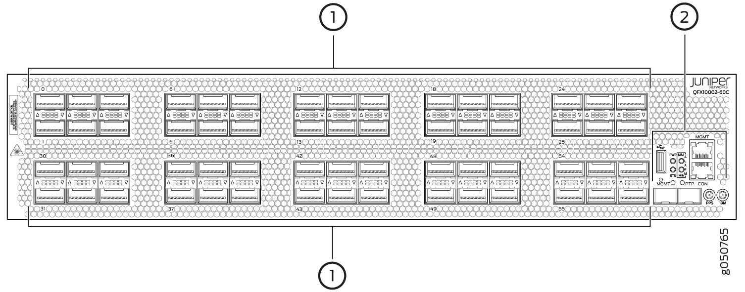
1 — Port panel with QSFP28 access interface or uplink ports (60) | 2 — Management panel |
This topic describes:
Overview
The QFX10002-60C ports support the flexible configuration of 100-Gbps, 40-Gbps, and 10-Gbps. Each port auto-senses a 100-Gbps QSFP28 or 40-Gbps QSFP transceiver and sets the speed accordingly. Any of the 60 ports, 0 through 59, can be configured as either uplink or access ports. See Table 3.
Per Port |
Per Switch |
Channelization |
|---|---|---|
1 x100 Gbps |
60 x 100 Gbps |
Non-channelized |
1 x 40 Gbps |
60 x 40 Gbps |
Non-channelized |
4 x 10 Gbps |
192 x 10 Gbps |
Network Ports
The QFX10002-60C supports the following types of optics and cables:
100-Gigabit Ethernet using 28-Gbps QSFP28 optical transceivers and 100-Gbps active optical cables (AOCs).
40-Gigabit Ethernet using QSFP+ optical transceivers, 40-Gbps AOCs, or 40-Gbps direct attach copper (DAC) cables.
10-Gigabit Ethernet using DAC breakout cables (DACBO). When configured for channelization, a breakout cable converts the 40-Gigabit Ethernet port into 4 independent 10-Gigabit Ethernet ports.
For a detailed list of supported optical transceivers and electrical cables, see The Hardware Compatibility Tool.
Channelization
Although the QFX10002-60C autosenses the speed of a transceiver and sets the speed to either 40 Gbps or 100 Gbps, for channelization you must manually configure the port speed. Any of the 60 physical ports that are configured for 40 Gbps speeds can be channelized to 4 independent 10-Gigabit Ethernet interfaces using copper or fiber breakout cables. You can channelize an individual port or a create a port range.
Port behavior is tied to the ASIC associated with the port. You must configure each port individually, in order to channelize a 40-Gigabit Ethernet port to 4 independent 10-Gigabit Ethernet ports. The first time a port for an associated ASIC is changed from the default configuration mode (mode D) to the channelization mode (mode A), the FPC reboots. Subsequent channelization of the ports for that ASIC does not cause the FPC to reboot. However if one of the channelized ports is changed back to the default, the FPC will again reboot. See Table 4 for the list of available ports and the associated ASIC.
Beginning in Junos OS 18.3R1, when the default configuration mode changes to the channelization mode, only the associated ASIC reboots.
The switch, as a whole, does not have port groups. However, there are five ports per ASIC, and within each ASIC, the fourth port cannot be channelized. When one of the other four ports is channelized, the forth port will be disabled, and the remaining three ports will continue to support 40-Gbps or 100-Gbps speeds. If ports in all 12 ASICs of the switch are channelized, the switch will have a maximum of 192 10-Gigabit Ethernet interfaces.
Changing the channelization mode (mode D to mode A or mode A to mode D) causes the FPC to reboot. Because there can be a slight loss of data while the FPC reboots, we recommend that you only configure the changes during a maintenance window.
|
ASIC |
Physical Ports available in each PFE |
Physical Ports Available for Channelization |
Physical Ports that Become Disabled |
|---|---|---|---|
|
PE0 |
30,32,34,36,38 | 30,32,34,38 |
36 |
|
PE1 |
31,33,35,37,39 |
31,33,35,39 |
37 |
|
PE2 |
40,42,44,46,48 |
40,42,44,48 |
46 |
|
PE3 |
41,43,45,47,49 |
41,43,45,49 |
47 |
|
PE4 |
50,52,54,56,58 |
50,52,54,58 |
56 |
|
PE5 |
51,53,55,57,59 |
51,53,55,59 |
57 |
|
PE6 |
0,2,4,6,8 |
0,2,4,8 |
6 |
|
PE7 |
1,3,5,7,9 |
1,3,5,9 |
7 |
|
PE8 |
10,12,14,16,18 |
10,12,14,18 |
16 |
|
PE9 |
11,13,15,17,19 |
11,13,15,19 |
17 |
|
PE10 |
20,22,24,26,28 |
20,22,24,28 |
26 |
|
PE11 |
21,23,25,27,29 |
21,23,25,29 |
27 |
To change from the default mode to 40-Gigabit Ethernet channelized mode, use the Junos OS operational command set chassis fpc slot-number pic 0 port port number speed 10g.
|
ASIC |
Physical Ports available in each PFE |
Physical Ports Available for Channelization |
Physical Ports that Become Disabled |
|---|---|---|---|
|
PE0 |
0,2,4,6,8 | 0,2,4,8 | 6 |
|
PE1 |
1,3,5,7,9 | 1,3,5,9 | 7 |
|
PE2 |
10,12,14,16,18 | 10,12,14,18 |
16 |
|
PE3 |
11,13,15,17,19 | 11,13,15,19 |
17 |
|
PE4 |
20,22,24,26,28 | 20,22,24,28 |
26 |
|
PE5 |
21,23,25,27,29 | 21,23,25,29 |
27 |
QFX10002-72Q Port Panel
The port panel of the QFX10002-72Q consists of 72 quad small-form factor pluggable plus (QSFP+) ports that support 10-Gbps, 40-Gbps and 100-Gbps port speeds. Of these 72 ports, 24 ports accept QSFP28 transceivers, which are dual speed 40- or 100-Gigabit Ethernet optical transceivers.
This topic describes:
Overview
Any of the 72 ports 0 through 71 can be configured as either uplink or access ports. See Figure 7.
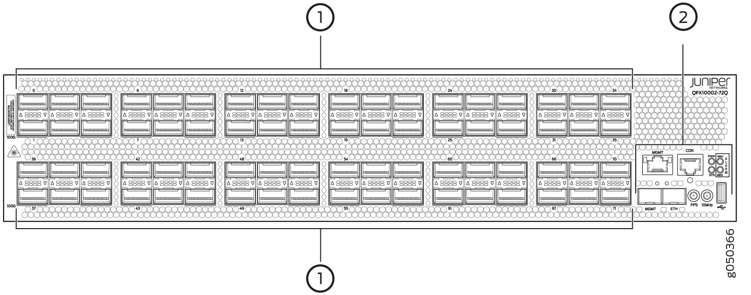
1 — Port panel with QSFP+ access interface or uplink ports (72) | 2 — Management panel |
The default configuration is independent 40-Gigabit Ethernet for all 72 ports. For 100-Gbps or 10-Gbps channelization operation, the ports operate within port groups. Every 3 ports compose a port group. See Table 6 and Figure 8 through Figure 11.
Per Port Group |
Per Switch |
|---|---|
1 x100 Gbps |
24 x 100 Gbps |
3 x 40 Gbps |
72 x 40 Gbps |
12 x 10 Gbps |
288 x 10 Gbps |
The second and sixth port in each 6XQSFP+ socket can be configured to support:
100-Gigabit Ethernet using 28-Gbps QSFP28 optical transceivers and 100-Gbps active optical cables (AOCs). When a QSFP28 transceiver is inserted into the ports marked with a fine black line underneath the socket and the port is configured for 100-Gigabit Ethernet, the two adjacent ports are disabled and the QSFP28 is enabled for 100-Gigabit Ethernet.
40-Gigabit Ethernet using QSFP+ optical transceivers or 40-Gbps direct attach copper (DAC) cables.
10-Gigabit Ethernet using DAC breakout cables (DACBO). When configured for channelization, a breakout cable converts the 40-Gigabit Ethernet port into 4 independent 10-Gigabit Ethernet ports.The two adjacent QSFP+ ports in the port group are also configured for channelization at the same time. You cannot configure a single port for channelization.
Switch Ports
Each of the 24 QSFP28 ports support:
100-Gigabit Ethernet QSFP28 transceivers
100-Gigabit Ethernet active optical cables (AOCs)
40-Gigabit Ethernet QSFP+ transceivers
40-Gigabit Ethernet QSFP+ DAC cables
40-Gigabit Ethernet QSFP+ to 10-Gigabit Ethernet SFP+ direct attach copper breakout (DACBO) cables
The remaining ports support:
40-Gigabit Ethernet QSFP+ transceivers
40-Gigabit Ethernet QSFP+ DAC cables
40-Gigabit Ethernet QSFP+ to 10-Gigabit Ethernet SFP+ DACBO cables
10-Gigabit Ethernet SFP+ transceivers
10-Gigabit Ethernet DAC cables
100-Gbps Operation and Configuration
Every second and sixth port in a 6XQSFP cage on a QFX10002 supports
100-Gigabit Ethernet using QSFP28 transceivers. These 100-Gigabit
Ethernet ports work either as 100-Gigabit Ethernet or as 40-Gigabit Ethernet,
but are recognized as 40-Gigabit Ethernet by default. See Figure 8 for a close up view of a 6XQSFP+
cage. The 100-Gigabit Ethernet are designated by a fine black line
underneath the port. See Figure 9. When a 40-Gigabit Ethernet transceiver is inserted into a
100-Gigabit Ethernet port, the port recognizes the 40-Gigabit Ethernet
port speed. However, when an 100-Gigabit Ethernet transceiver is inserted
into the port, the transceiver is not automatically recognized and
is not seen in the output of the show chassis hardware command.
To enable 100-Gigabit Ethernet on the marked ports, use the set
chassis fpc command. For example, to enable port 71 for 100
Gbps speeds:
[edit]
user@switch#
set chassis fpc 0 pic 0 port 71 speed 100g
The port then recognizes the 100-Gigabit Ethernet speed and disables two adjacent 40-Gigabit Ethernet ports. See Figure 10.
Figure 8 shows the location of QSFP+ ports for the QFX10002-72Q.
40-Gbps Channelization
The 40-Gigabit Ethernet ports can operate independently
or bundled with the next two consecutive ports and channelized into
twelve 10-Gigabit Ethernet ports as a port group. Like 100-Gigabit
channelization, only the first and fourth port in each 6XQSFP cage
are available to channelize a port group (see Figure 11). The port group must be configured
using the set chassis fpc pic port channel-speed command.
For example, to channelize the first switch port, use the set
chassis fpc 0 pic 0 port 1 channel-speed 10g command.
Port Mapping
Table 7 shows the available combinations for the ports. Most 100-Gigabit Ethernet transceiver ports are used as uplinks . On the QFX10002, the ports are enabled by default and the default configuration adds the ports to the default VLAN.
Port Number |
4X10 Gigabit Channelized Port |
4X10 Gigabit Channelized Port Group |
40 Gigabit Ethernet (Default) |
100 Gigabit Ethernet |
100 Gigabit Ethernet Disables |
|---|---|---|---|---|---|
0 |
✓ |
✓ |
✓ |
– |
– |
1 |
✓ |
✓ |
✓ |
0, 2 |
|
2 |
✓ |
✓ |
– |
– |
|
3 |
✓ |
✓ |
✓ |
– |
– |
4 |
✓ |
✓ |
– |
– |
|
5 |
✓ |
✓ |
✓ |
3, 4 |
|
6 |
✓ |
✓ |
✓ |
– |
– |
7 |
✓ |
✓ |
✓ |
6, 8 |
|
8 |
✓ |
✓ |
– |
– |
|
9 |
✓ |
✓ |
✓ |
– |
– |
10 |
✓ |
✓ |
– |
– |
|
11 |
✓ |
✓ |
✓ |
9, 10 |
|
12 |
✓ |
✓ |
✓ |
– |
– |
13 |
✓ |
✓ |
✓ |
12, 14 |
|
14 |
✓ |
✓ |
– |
– |
|
15 |
✓ |
✓ |
✓ |
– |
– |
16 |
✓ |
✓ |
– |
– |
|
17 |
✓ |
✓ |
✓ |
15, 16 |
|
18 |
✓ |
✓ |
✓ |
– |
– |
19 |
✓ |
✓ |
✓ |
18, 20 |
|
20 |
✓ |
✓ |
– |
– |
|
21 |
✓ |
✓ |
✓ |
– |
– |
22 |
✓ |
✓ |
– |
– |
|
23 |
✓ |
✓ |
✓ |
21, 22 |
|
24 |
✓ |
✓ |
✓ |
– |
– |
25 |
✓ |
✓ |
✓ |
24, 26 |
|
26 |
✓ |
✓ |
– |
– |
|
27 |
✓ |
✓ |
✓ |
– |
– |
28 |
✓ |
✓ |
– |
– |
|
29 |
✓ |
✓ |
✓ |
27, 28 |
|
30 |
✓ |
✓ |
✓ |
– |
– |
31 |
✓ |
✓ |
✓ |
30, 32 |
|
32 |
✓ |
✓ |
– |
– |
|
33 |
✓ |
✓ |
✓ |
– |
– |
34 |
✓ |
✓ |
– |
– |
|
35 |
✓ |
✓ |
✓ |
33, 34 |
|
36 |
✓ |
✓ |
✓ |
– |
– |
37 |
✓ |
✓ |
✓ |
36, 38 |
|
38 |
✓ |
✓ |
– |
– |
|
39 |
✓ |
✓ |
✓ |
– |
– |
40 |
✓ |
✓ |
– |
– |
|
41 |
✓ |
✓ |
✓ |
39, 40 |
|
42 |
✓ |
✓ |
✓ |
– |
– |
43 |
✓ |
✓ |
✓ |
42, 44 |
|
44 |
✓ |
✓ |
– |
– |
|
45 |
✓ |
✓ |
✓ |
– |
– |
46 |
✓ |
✓ |
– |
– |
|
47 |
✓ |
✓ |
✓ |
45, 46 |
|
48 |
✓ |
✓ |
✓ |
– |
– |
49 |
✓ |
✓ |
✓ |
48, 50 |
|
50 |
✓ |
✓ |
– |
– |
|
51 |
✓ |
✓ |
✓ |
– |
– |
52 |
✓ |
✓ |
– |
– |
|
53 |
✓ |
✓ |
✓ |
51, 52 |
|
54 |
✓ |
✓ |
✓ |
– |
– |
55 |
✓ |
✓ |
✓ |
54, 56 |
|
56 |
✓ |
✓ |
– |
– |
|
57 |
✓ |
✓ |
✓ |
– |
– |
58 |
✓ |
✓ |
– |
– |
|
59 |
✓ |
✓ |
✓ |
57, 58 |
|
60 |
✓ |
✓ |
✓ |
– |
– |
61 |
✓ |
✓ |
✓ |
60, 62 |
|
62 |
✓ |
✓ |
– |
– |
|
63 |
✓ |
✓ |
✓ |
– |
– |
64 |
✓ |
✓ |
– |
– |
|
65 |
✓ |
✓ |
✓ |
63, 64 |
|
66 |
✓ |
✓ |
✓ |
– |
– |
67 |
✓ |
✓ |
✓ |
66, 68 |
|
68 |
✓ |
✓ |
– |
– |
|
69 |
✓ |
✓ |
✓ |
– |
– |
70 |
✓ |
✓ |
– |
– |
|
71 |
✓ |
✓ |
✓ |
69, 70 |
Only channelized ports can be configured as 10-G ports.
QFX10002 Network Port LEDs
Each QFX10002 QSFP+ port uses a single bi-colored LED to indicate link status and activity. See Figure 12 for an example of these triangle shaped LEDs.
The same single bi-colored LED also indicates when the interface is configured and connected using an optical split cable or a copper DACBO cable to a 10-Gigabit Ethernet port.
There are some slight differences in the amber LED behavior
depending on the firmware level of the complex programmable logic
device (CPLD) in your switch and the Junos release level running on
the switch. To determine the Junos release level, use the show
version command. To determine the CPLD of your switch, use the show chassis firmware command. For example:
root@> show chassis firmware
Part                     Type       Version
FPC 0                    U-Boot      ***
                         loader           FreeBSD/i386 bootstrap loader 1.2
                         BIOS       V0018.2U
                         EC FPGA    2.3
                         MAIN_CPLD  1.10
                         MEZZ_CPLD  1.10
                         RE FPGA    2.4
root@>
See Table 8 for how to interpret the QSFP+ LEDs.
Color |
State |
Description |
|---|---|---|
Unlit |
Off |
The port is administratively disabled, there is no power, the link is down, or a transceiver is not present. All sub-channels are disabled. |
Green |
On steadily |
A link is established. When channelized, all sub-channels are up. When not channelized, it indicates no activity. |
Slow blinking (250 ms on and 1750 ms off) |
The beacon function was enabled on the port. |
|
Blinking (500 ms on and 500 ms off) |
When channelized, all four channels are up and active. When not channelized, it indicates the port is up and active in either 40-Gigabit or 100-Gigabit mode. |
|
Amber |
On steadily |
For Junos Release 15.1X53-D21 or later and
CPLD version V1.16 or later: One or more breakout connections (sub-channels) are up. However not all sub-channels are up and there is no port activity. |
| For Junos Release 15.1X53-D10 to 15.1X53-D20
and CPLD version V1.10: Solid yellow LED is not available. |
||
Blinking |
One or more breakout connections (sub-channels) are up. At least one sub-channel has activity, but not all connections are active. |