Fast Track to Rack Installation and Power
This procedure guides you through the simplest steps for the most common installation to get your NFX350 device in a rack and connect it to power.
Install the NFX350 in a Rack
You can install the NFX350 device on a desktop or other level surface, on four-post racks . We’ll walk you through the steps to install an NFX350 device
Before you install, review the following:
Mount the NFX350 Device
To mount the device on four posts in a rack
-
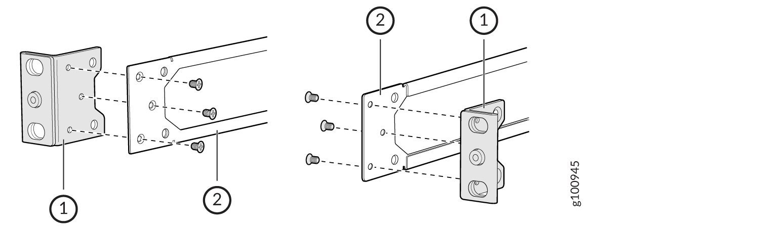
Attach the front-mounting brackets (either the flush or the 2-in.-recess
front-mounting brackets) to the side mounting rails by using the six 4-40
flat-head Phillips mounting screws. See Figure 1.
Figure 1: Attaching the Front-Mounting Bracket to the Side Mounting-Rail
-
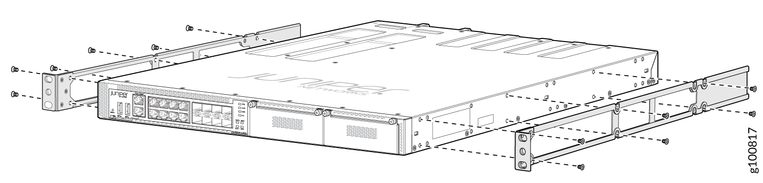
Insert M4x6-mm Phillips flat-head mounting screws into the two aligned
holes and tighten the screws. Ensure that the remaining two holes in the
front bracket are aligned with the two holes in the side panel. See Figure 2.
Figure 2: Attaching the Front-Mounting Bracket to the Device Chassis
-
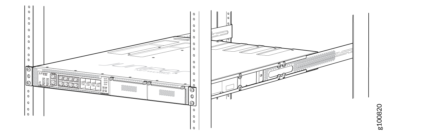
Have one person grasp both sides of the device, lift the device, and
position it in the rack, aligning the front bracket holes with the threaded
holes in the front post of the rack. Align the bottom hole in both the
front-mounting brackets with a hole in each rack rail, making sure the
chassis is level. See Figure 3
and Figure 4 .
Figure 3: Attaching the Device to the Rack
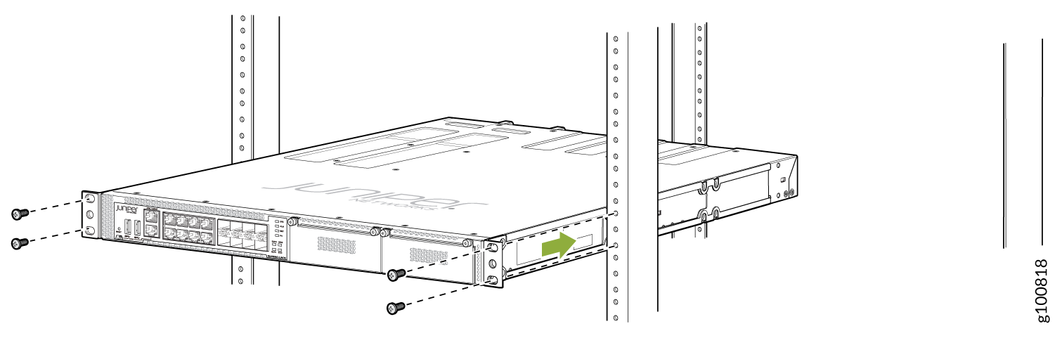 Figure 4: Mounting the Device on the Front Posts in a Rack
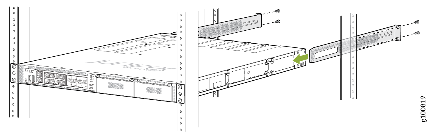
-
Ensure that the device chassis is level by verifying that all the screws on
the front of the rack are aligned with the screws at the back of the rack.
See Figure 5.
Figure 5: Rack Mounted NFX350 Device
Connect to Power
Before you connect the NFX350 device to power, you must ground the NFX350 device.
Ground the NFX350 Device
To ground the NFX350 device, do the following:
-
Connect one end of the grounding cable to a proper earth ground, such as the rack in which the device is mounted.
-
Place the grounding lug attached to the grounding cable over the protective earthing terminal. See Figure 6 .
Figure 6: Connecting a Grounding Cable to an NFX350 Device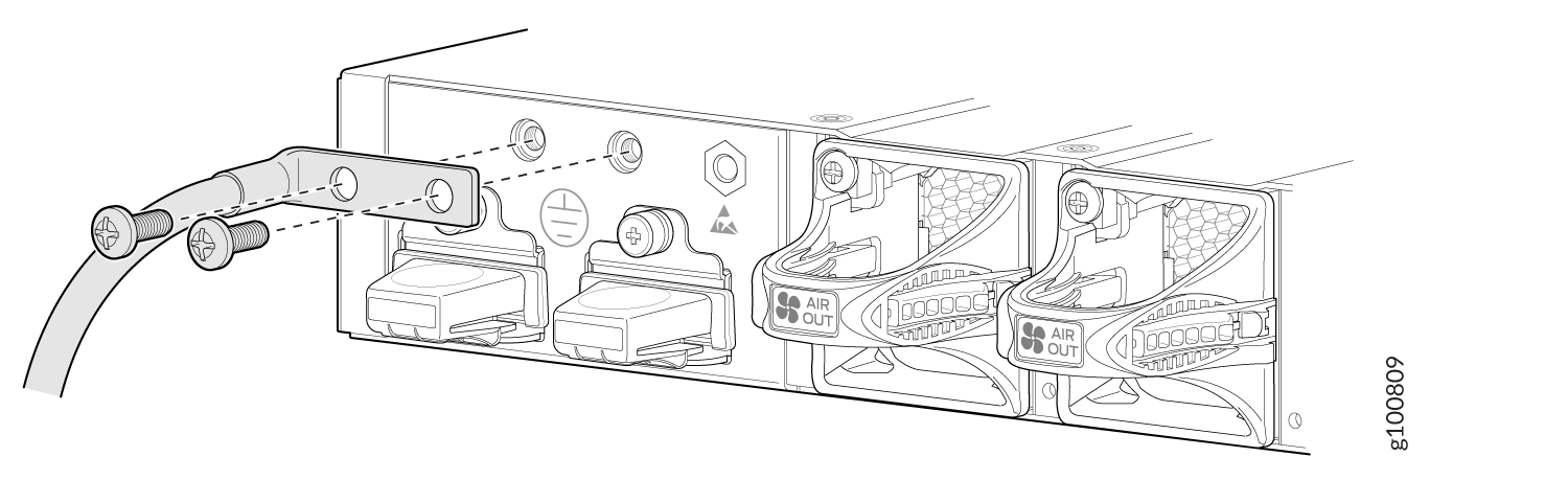
-
Secure the grounding lug to the protective earthing terminal with the washers and screws.
-
Dress the grounding cable and ensure that it does not touch or block access to other device components.
Warning:Ensure that the cable does not drape where people could trip over it.
Connecting AC Power to an NFX350 Device
Ensure that you have the following parts and tools available:
-
A power cord appropriate for your geographical location
-
A power cord retainer clip
NFX350 device gets additional grounding when you plug the power supply in the device into a grounded AC power outlet by using the AC power cord appropriate for your geographical location (see AC Power Cord Specifications for an NFX350 Device).
The power supply in an NFX350 device is located on the rear panel.
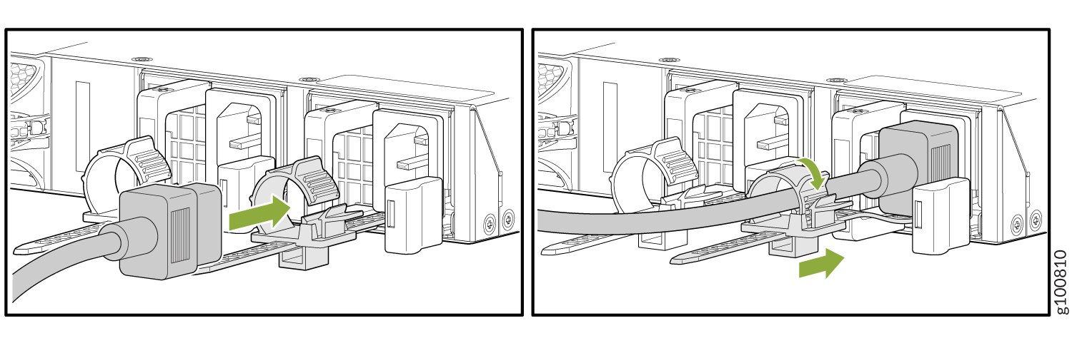
To connect AC power to the NFX350 device:
The retainer brackets on your device might be above and below the power inlet rather than on either side.
Connecting DC Power to an NFX350 Device
Before you begin connecting DC power to the NFX350 device, ensure that you have connected earth ground to the NFX350 device.
Before you connect power to the device, a licensed electrician must attach a cable lug to the grounding and power cables that you supply. A cable with an incorrectly attached lug can damage the device (for example, by causing a short circuit).
To meet safety and electromagnetic interference (EMI) requirements and to ensure proper operation, you must connect the device to earth ground before you connect them to power. For installations that require a separate grounding conductor to the device, use the protective earthing terminal on the device to connect to the earth ground. For instructions on connecting earth ground, see Connecting Earth Ground to an NFX350 Device.
Grounding is required for DC systems and recommended for AC systems. An AC-powered device gets additional grounding when you plug the power supply in the device into a grounded AC power outlet by using the AC power cord appropriate for your geographical location.
DC-powered devices are intended for installation only in a restricted access location.
To connect DC power to the NFX350 device:
-
Install heat-shrink tubing insulation around the power cables:
-
Slide the tubing over the portion of the cable where it is attached to the lug barrel. Ensure that the tubing covers the end of the wire and the barrel of the lug attached to it.
-
Shrink the tubing with a heat gun. Ensure that you heat all sides of the tubing evenly so that it shrinks around the cable tightly.
Note:Do not overheat the tubing.
Figure 8 shows how to install heat-shrink tubing.
Figure 8: How to Install Heat-Shrink Tubing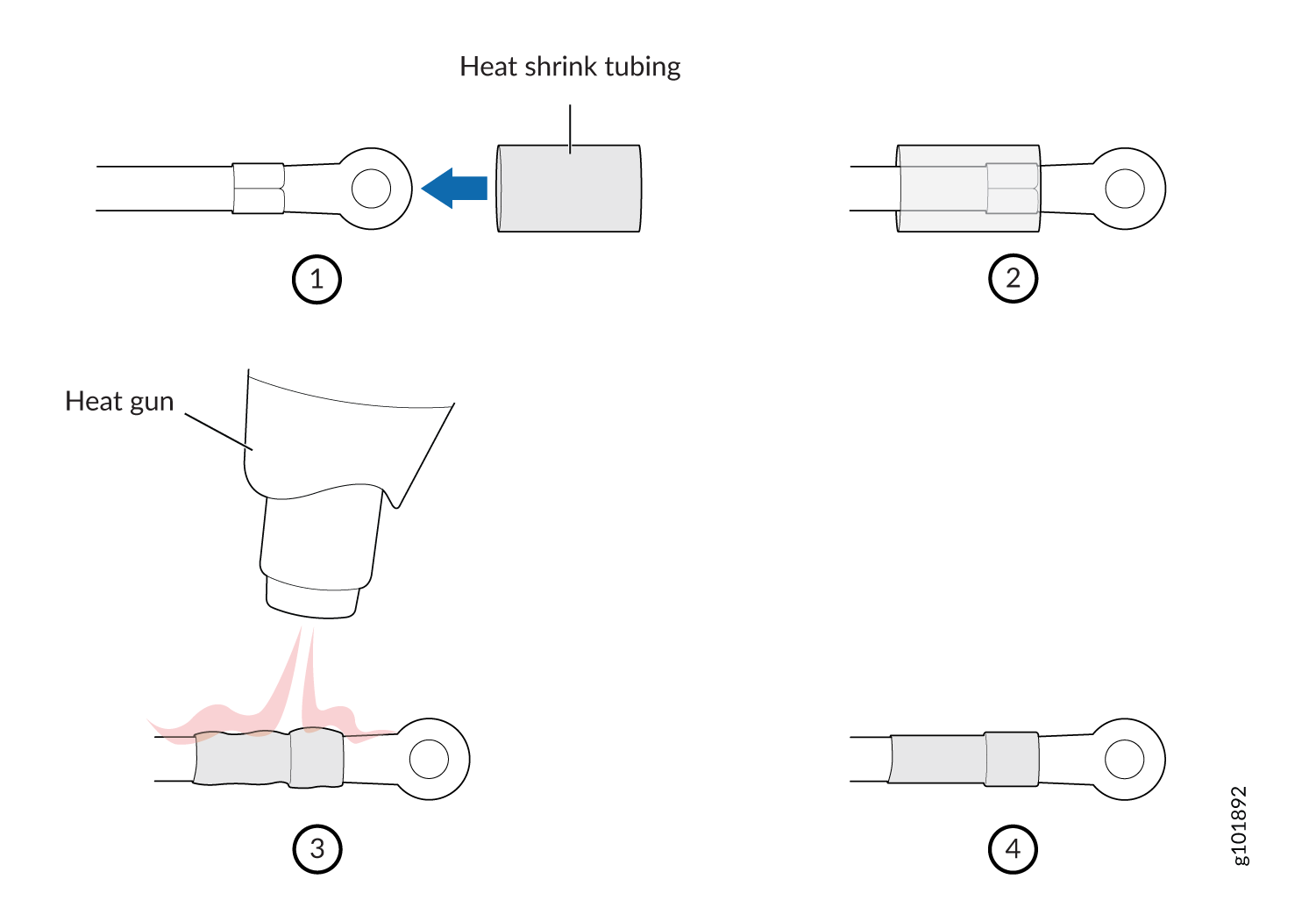
-
-
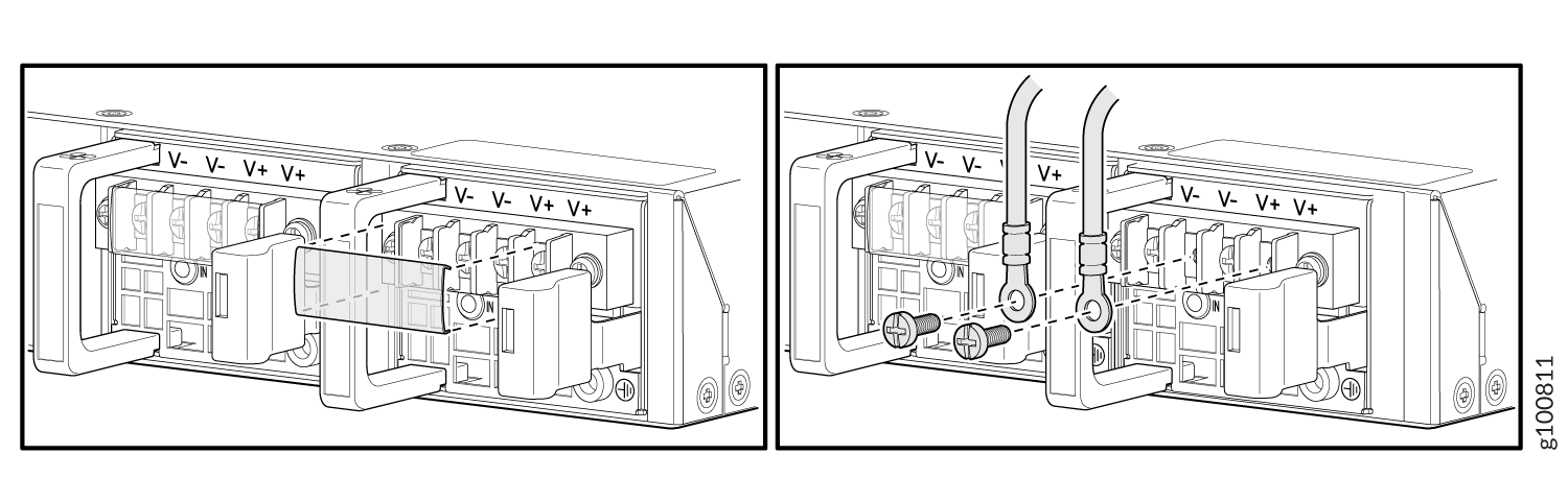
Connect the power supply to the power sources. Secure power source cables
to the power supply by screwing the ring lugs attached to the cables to the
appropriate terminals by using the screw from the terminals.
Figure 9: Connecting a DC Power Cord to the DC Power Cord Inlet on NFX350 Device
-
To connect the power supply to a power source:
-
Secure the ring lug of the positive (+) DC power source cable to the A+ or B+ terminal on the DC power supply.
-
Secure the ring lug of the negative (–) DC power source cable to the A– or B– terminal on the DC power supply.
-
Tighten the screws on the power supply terminals until snug by using the screwdriver. Do not overtighten—apply between 8 in.-lb (0.9 Nm) and 9 in.-lb (1.02 Nm) of torque to the screws.
-
-
To connect the power supply to two power sources:
-
Secure the ring lug of the positive (+) DC power source cable from the first DC power source to the A+ terminal on the power supply.
-
Secure the ring lug of the negative (–) DC power source cable from the first DC power source to the A– terminal on the power supply.
-
Secure the ring lug of the positive (+) DC power source cable from the second DC power source to the B+ terminal on the power supply.
-
Secure the ring lug of the negative (–) DC power source cable from the second DC power source to the B– terminal on the power supply.
-
Tighten the screws on the power supply terminals on both the power supplies until snug by using the screwdriver. Do not overtighten—apply between 8 in.-lb (0.9 Nm) and 9 in.-lb (1.02 Nm) of torque to the screws.
-
-