Connecting the NFX350 to Power
Connecting Earth Ground to an NFX350 Device
Earth grounding is recommended, but optional for the NFX350 device. The device functions normally without earth grounding. Electromagnetic Compatibility (EMC) and Electrostatic Discharge (ESD) requirements are met by the device. The AC power cord provides surge protection.
You must install the NFX350 device in a restricted-access location and ensure that the chassis is always properly grounded. The NFX350 device has a two-hole protective grounding terminal provided on the chassis. See Figure 1. We recommend that you use this protective grounding terminal as the preferred method for grounding the chassis regardless of the power supply configuration. However, if additional grounding methods are available, you can also use those methods. For example, you can use the grounding wire in the AC power cord or use the grounding terminal or lug on a DC power supply. This tested system meets or exceeds all applicable EMC regulatory requirements with the two-hole protective grounding terminal.
This topic describes:
- Parts and Tools Required for Connecting an NFX350 Device to Earth Ground
- Connecting Earth Ground to an NFX350 Device
Parts and Tools Required for Connecting an NFX350 Device to Earth Ground
Table 1 lists the earthing terminal location, grounding cable requirements, grounding lug specifications, screws and washers required, and the screwdriver needed for connecting a device to earth ground. Before you begin connecting a device to earth ground, ensure you have the parts and tools required for your device.
|
Device |
Earthing Terminal Location |
Grounding Cable Requirements |
Grounding Lug Specifications |
Screws and Washers |
Screwdriver |
|---|---|---|---|---|---|
|
NFX350 |
Rear panel of the device |
14 AWG (2 mm²), minimum 90°C wire, or as permitted by the local code |
Panduit LCC10-14BWL or equivalent—not provided |
|
Phillips (+) number 2 |
Connecting Earth Ground to an NFX350 Device
To connect earth ground to a device:
-
Connect one end of the grounding cable to a proper earth ground, such as the rack in which the device is mounted.
-
Place the grounding lug attached to the grounding cable over the protective earthing terminal. See Figure 1.
Figure 1: Connecting a Grounding Cable to an NFX350 Device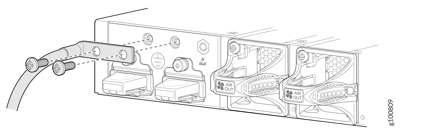
-
Secure the grounding lug to the protective earthing terminal with the washers and screws.
-
Dress the grounding cable and ensure that it does not touch or block access to other device components.
Warning:Ensure that the cable does not drape where people could trip over it.
Connecting AC Power to an NFX350 Device
Ensure that you have the following parts and tools available:
-
A power cord appropriate for your geographical location
-
A power cord retainer clip
NFX350 device gets additional grounding when you plug the power supply in the device into a grounded AC power outlet by using the AC power cord appropriate for your geographical location (see AC Power Cord Specifications for an NFX350 Device).
The power supply in an NFX350 device is located on the rear panel.
Figure 2 and Figure 3 show the AC power supply unit for the NFX350 device.
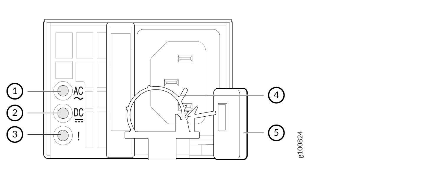
1 — Input status LED | 4 — AC power cord retainer installed |
2 — Output status LED | 5 — Ejector level |
3 — Fault LED |
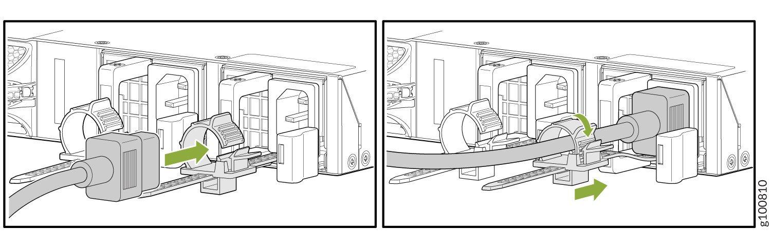
To connect AC power to the device:
The retainer brackets on your device might be above and below the power inlet rather than on either side.
Connecting DC Power to an NFX350 Device
Before you begin connecting DC power to the NFX350 device, ensure that you have connected earth ground to the NFX350 device.
Before you connect power to the device, a licensed electrician must attach a cable lug to the grounding and power cables that you supply. A cable with an incorrectly attached lug can damage the device (for example, by causing a short circuit).
To meet safety and electromagnetic interference (EMI) requirements and to ensure proper operation, you must connect the device to earth ground before you connect them to power. For installations that require a separate grounding conductor to the device, use the protective earthing terminal on the device to connect to the earth ground. For instructions on connecting earth ground, see Connecting Earth Ground to an NFX350 Device.
Grounding is required for DC systems and recommended for AC systems. An AC-powered device gets additional grounding when you plug the power supply in the device into a grounded AC power outlet by using the AC power cord appropriate for your geographical location.
Ensure that you have the following parts and tools available:
-
DC power source cables (14 AWG) with ring lug (Molex 0190700067 or equivalent) (not provided) attached to them by a licensed electrician
-
Phillips (+) screwdriver, number 2
DC-powered devices are intended for installation only in a restricted access location.
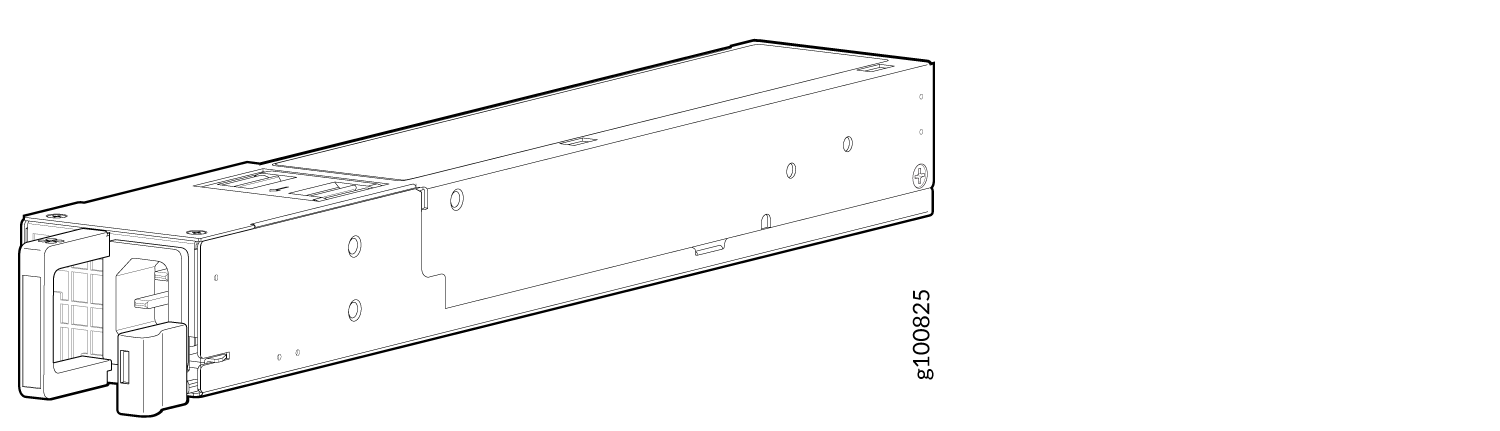
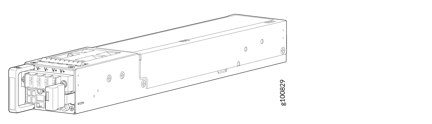
Figure 5 and Figure 6 show the AC power supply unit for the NFX350 device.
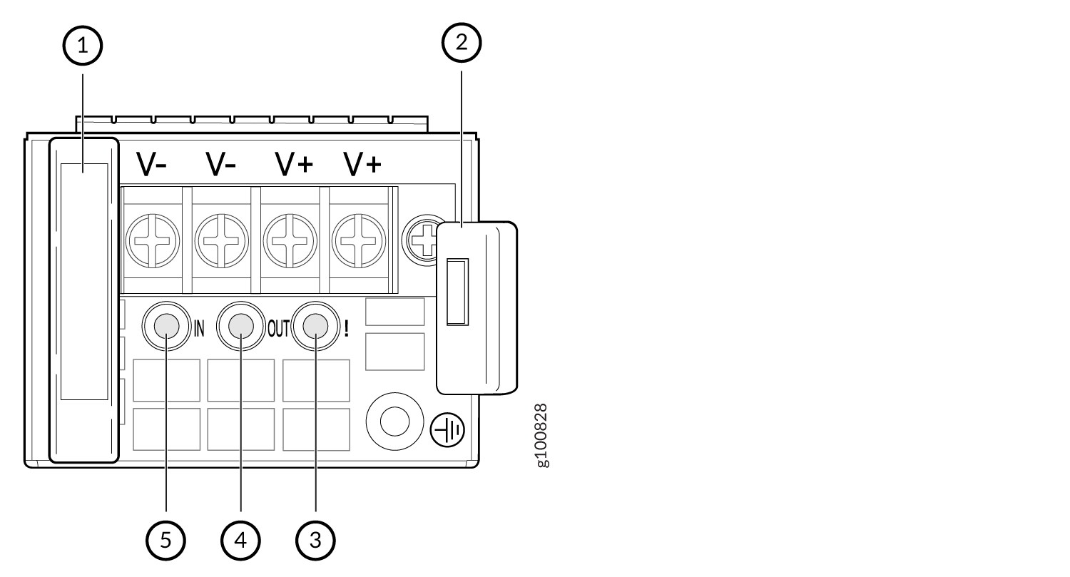
1 — Handle | 4 — Output LED |
2 — Ejector level | 5 — Input LED |
3 — Fault LED |
To connect DC power to the NFX350 device:
-
Install heat-shrink tubing insulation around the power cables:
-
Slide the tubing over the portion of the cable where it is attached to the lug barrel. Ensure that the tubing covers the end of the wire and the barrel of the lug attached to it.
-
Shrink the tubing with a heat gun. Ensure that you heat all sides of the tubing evenly so that it shrinks around the cable tightly.
Note:Do not overheat the tubing.
Figure 7 shows how to install heat-shrink tubing.
Figure 7: How to Install Heat-Shrink Tubing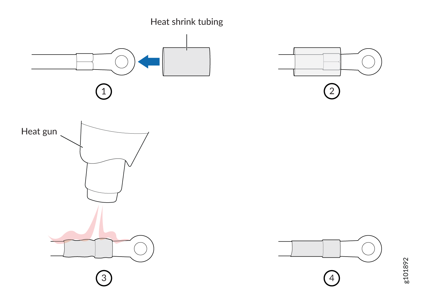
-
-
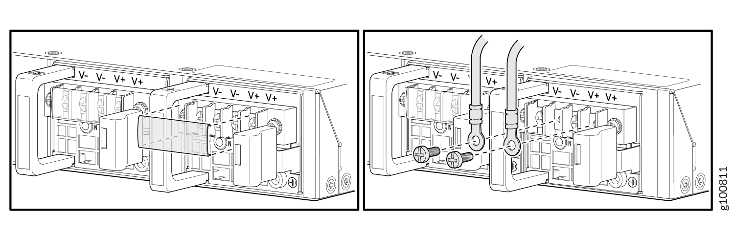
Connect the power supply to the power sources. Secure power source cables to
the power supply by screwing the ring lugs attached to the cables to the
appropriate terminals by using the screw from the terminals.
Figure 8: Connecting a DC Power Cord to the DC Power Cord Inlet on NFX350 Device
-
To connect the power supply to a power source:
-
Secure the ring lug of the positive (+) DC power source cable to the A+ or B+ terminal on the DC power supply.
-
Secure the ring lug of the negative (–) DC power source cable to the A– or B– terminal on the DC power supply.
-
Tighten the screws on the power supply terminals until snug by using the screwdriver. Do not overtighten—apply between 8 in.-lb (0.9 Nm) and 9 in.-lb (1.02 Nm) of torque to the screws.
-
-
To connect the power supply to two power sources:
-
Secure the ring lug of the positive (+) DC power source cable from the first DC power source to the A+ terminal on the power supply.
-
Secure the ring lug of the negative (–) DC power source cable from the first DC power source to the A– terminal on the power supply.
-
Secure the ring lug of the positive (+) DC power source cable from the second DC power source to the B+ terminal on the power supply.
-
Secure the ring lug of the negative (–) DC power source cable from the second DC power source to the B– terminal on the power supply.
-
Tighten the screws on the power supply terminals on both the power supplies until snug by using the screwdriver. Do not overtighten—apply between 8 in.-lb (0.9 Nm) and 9 in.-lb (1.02 Nm) of torque to the screws.
-
-