ON THIS PAGE
Connecting the NFX150 to the Network
Connecting an NFX150 Device to a Network for Out-of-Band Management
Ensure that you have an appropriate cable available.
You can monitor and manage the NFX150 device using a dedicated management channel. NFX150 devices have one management port, eight 1-Gigabit Ethernet RJ-45 ports, two 1-Gigabit Ethernet RJ-45 network/uplink ports, two 1-Gigabit Ethernet small form-factor pluggable (SFP) ports, and two 1/10-Gigabit Ethernet SFP+ ports. Use the management port to connect the NFX150 device to a network for out-of-band management.
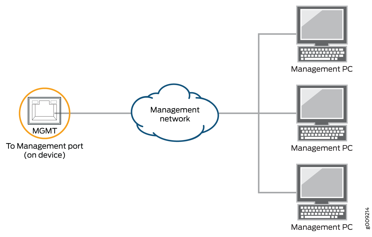
To connect an NFX150 device to a network for out-of-band management (see Figure 1):
- Connect one end of the cable to the management port (labeled MGMT) on the NFX150 device.
- Connect the other end of the cable to the management switch (see Figure 1).
See Also
Connecting an NFX150 Device to a Management Console
Ensure that you have an RJ-45 to DB-9 rollover cable available.
We no longer include the console cable as part of the device package. If the console cable and adapter are not included in your device package, or if you need a different type of adapter, you can order the following separately:
-
RJ-45 to DB-9 adapter (JNP-CBL-RJ45-DB9)
-
RJ-45 to USB-A adapter (JNP-CBL-RJ45-USBA)
-
RJ-45 to USB-C adapter (JNP-CBL-RJ45-USBC)
If you want to use RJ-45 to USB-A or RJ-45 to USB-C adapter you must have X64 (64-Bit) Virtual COM port (VCP) driver installed on your PC. See, https://ftdichip.com/drivers/vcp-drivers/ to download the driver.
If your laptop or PC does not have a DB-9 plug connector pin and you want to connect your laptop or PC directly to the NFX150 device, use a combination of the RJ-45 cable and RJ-45 to DB-9 adapter supplied with the device and a USB to DB-9 plug adapter. You must provide the USB to DB-9 plug adapter.
NFX150 device has a console port with an RJ-45 connector. Use the console port to connect the device to a management console or to a console server.
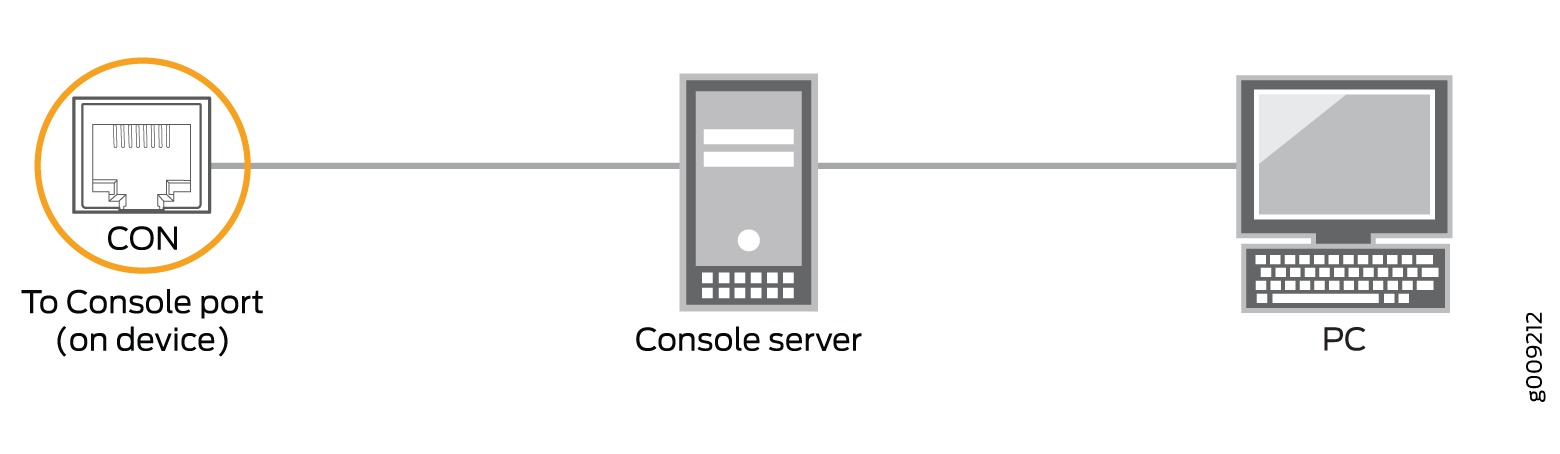
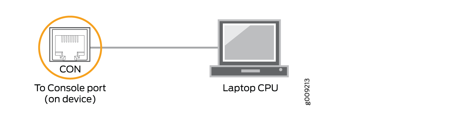
To connect the NFX150 device to a management console (see Figure 2 and Figure 3):
- Connect one end of the Ethernet cable to the console port (labeled CON).
- Connect the other end of the Ethernet cable into the console server (see Figure 2) or management console (see Figure 3).
See Also
Connecting an NFX150 Device to a Management Console Using Mini-USB Type-B Console Port
Before you begin connecting an NFX150 device by using the Mini-USB Type-B console port:
Ensure that the USB to Serial driver is installed on the host machine. You can download the driver from https://webdownload.juniper.net/swdl/dl/secure/site/1/record/5029.html
Ensure that the hyper terminal properties of the console server or laptop are set as follows:
Baud rate—9600
Flow control—None
Data—8
Parity—None
Stop bits—1
DCD state—Disregard
Ensure that you have the following parts and tools available:
1 mini-USB cable with Standard-A and Mini-USB Type- B (5-pin) connectors (not provided).
You can configure and manage NFX150 devices by using the RJ-45 console port or the Mini-USB Type-B console port. However, the console input will be active only on one port at a time—only one port will be set active at a time.
By default, the RJ-45 port is set as an active console port and the Mini-USB Type-B port is the passive console port.
If your laptop or PC does not have a DB-9 plug connector pin or RJ-45 connector pin, you can connect your laptop or PC directly to an NFX150 device by using a mini-USB cable that has a Standard-A USB connector on one end and a Mini-USB Type-B (5 pin) connector on the other end.
This section describes the process of connecting an NFX150 device to the management console by using the Mini-USB Type-B console port.
For information about configuring and managing an NFX150 device by using the RJ-45 console port, see Connecting an NFX150 Device to a Management Console.
To connect the NFX150 device to the console using Mini-USB Type-B console port:
- Connect the Standard-A connector of the mini-USB cable to the host machine (PC or Laptop).
- Connect the Mini-USB Type-B (5-pin) connector of the mini-USB cable to the Mini-USB Type-B console port (labeled CON) on the NFX150 device.
- Set the Mini-USB Type-B console port as the active console
port by using the command
port-type. - Reboot the NFX150 device.
After the connection is established, the Mini-USB Type-B becomes the active console port. The host machine connected to the Mini-USB Type-B console port displays log messages and lets you control NFX150 device functionality through it.
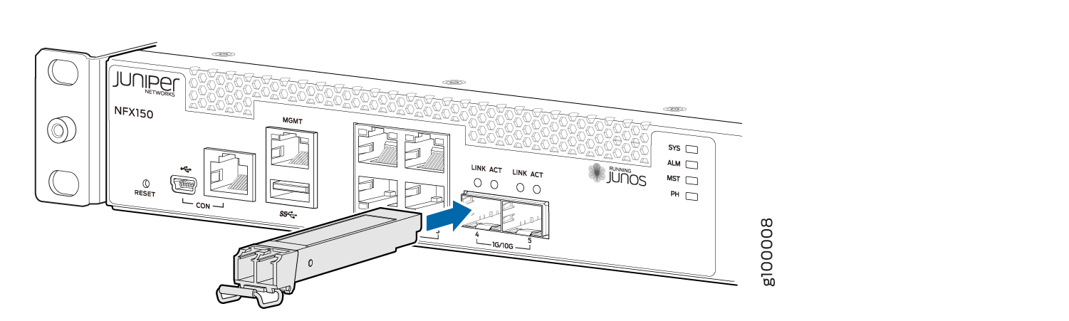
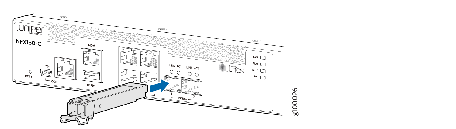
Installing a Transceiver in an NFX150 Device
Before you begin installing a transceiver in an NFX150 device, ensure that you have taken the necessary precautions for safe handling of lasers (see Laser and LED Safety Guidelines and Warnings for the NFX150 Devices).
Ensure that you have a rubber safety cap available to cover the transceiver.
The transceivers for the NFX150 devices are hot-removable and hot-insertable field-replaceable units (FRUs). You can remove and replace them without powering off the device or disrupting device functions.
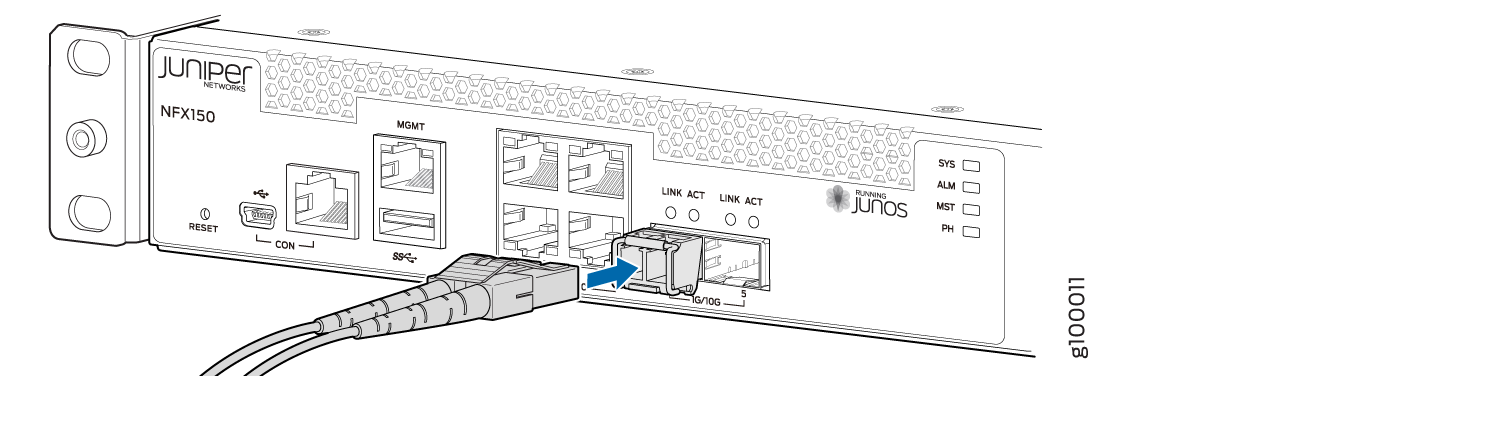
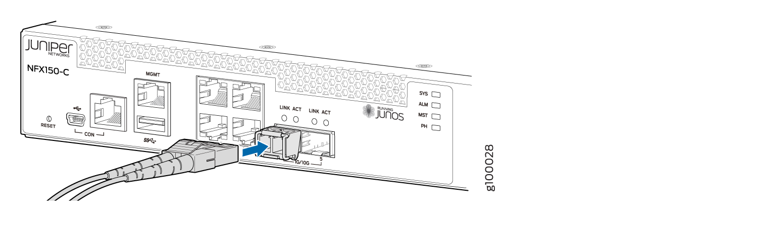
To install a transceiver in a NFX150 device:
To avoid electrostatic discharge (ESD) damage to the transceiver, do not touch the connector pins at the end of the transceiver.
Connecting a Fiber-Optic Cable to an NFX150 Device
Before you connect a fiber-optic cable to an optical transceiver installed in an NFX150 device, ensure that you have taken the necessary precautions for safe handling of lasers (see Laser and LED Safety Guidelines and Warnings for the NFX150 Devices).
You can connect fiber-optic cables to the field-replaceable unit (FRU) optical transceivers installed in NFX150 devices.
To connect a fiber-optic cable to an optical transceiver installed in an NFX150 device:
Do not look directly into a fiber-optic transceiver or into the ends of fiber-optic cables. Fiber-optic transceivers and fiber-optic cables connected to transceivers emit laser light that can damage your eyes.
Do not stare into the laser beam or view it directly with optical instruments even if the interface has been disabled.