MX304 Power Planning
Calculating Power Requirements for MX304 Router
Power Requirements for MX304 Components
Table 1 displays the power requirements at different ambient temperatures for the router with two routing engines and two LMICs (100-Gigabit Ethernet ports with QSFP28 transceivers on each LMIC).
| Module | Quantity | Each Module Power (W) @ 25° C | Each Module Power (W) @ 46° C | Total Module Power (W) @ 25° C | Total Module Power (W) @ 46° C |
|---|---|---|---|---|---|
| Routing Engine (RE) (Active) | 1 | 49 | 59 | 49 | 59 |
| Routing Engine (RE) (Standby) approximate | 1 | 49 | 59 | 49 | 59 |
| Switch Fabric Board (SFB)+Control Board(CB)+Processor Mezzanine Board(PMB) | 3 | 155 | 228 | 155 | 228 |
| LMIC + 16x100-Gigabit Ethernet (5 W transceivers) | 2 | 318 | 410 | 636 | 820 |
| Fans | 3 | 48 | 90 | 144 | 270 |
| Total Chassis Power (W) | 1033 | 1436 | |||
Table 2 displays the power requirements at different ambient temperatures for the router with two routing engines and two LMICs (400-Gigabit Ethernet ports with QSFP-DD transceivers on each LMIC).
| Module | Quantity | Each Module Power (W) @ 25° C | Each Module Power (W) @ 46° C | Total Module Power (W) @ 25° C | Total Module Power (W) @ 46° C |
|---|---|---|---|---|---|
| Routing Engine (Active) | 1 | 49 | 59 | 49 | 59 |
| Routing Engine (Standby) approximate | 1 | 49 | 59 | 49 | 59 |
| Switch Fabric Board (SFB)+Control Board(CB)+Processor Mezzanine Board(PMB) | 3 | 155 | 228 | 155 | 228 |
| LMIC + 4x400-Gigabit Ethernet (20 W transceivers) | 2 | 318 | 386 | 636 | 772 |
| Fans | 3 | 48 | 90 | 144 | 270 |
| Total Chassis Power (W) | 1033 | 1388 | |||
Table 3 displays the power requirements at different ambient temperatures for the router with routing engines and three LMICs (100-Gigabit Ethernet Ports with QSFP28 transceivers on each LMIC).
| Module | Quantity | Each Module Power (W) @ 25° C | Each Module Power (W) @ 46° C | Total Module Power (W) @ 25° C | Total Module Power (W) @ 46° C |
|---|---|---|---|---|---|
| Routing Engine (Active) | 1 | 49 | 59 | 49 | 59 |
| Routing Engine (Standby) approximate | 0 | 49 | 59 | 0 | 0 |
| Switch Fabric Board (SFB)+Control Board(CB)+Processor Mezzanine Board(PMB) | 3 | 185 | 246 | 211 | 246 |
| LMIC + 16x100-Gigabit Ethernet (5 W transceivers) | 3 | 318 | 410 | 1029 | 1230 |
| Fans | 3 | 57 | 95 | 225 | 285 |
| Total Chassis Power (W) | 1514 | 1820 | |||
Table 4 displays the power requirements at different ambient temperatures for routers with one routing engine and three LMICs (400-Gigabit Ethernet ports with QSFP-DD transceivers on each LMIC).
| Module | Quantity | Each Module Power (W) @ 25° C | Each Module Power (W) @ 46° C | Total Module Power (W) @ 25° C | Total Module Power (W) @ 46° C |
|---|---|---|---|---|---|
| Routing Engine (Active) | 1 | 49 | 59 | 49 | 59 |
| Routing Engine (Standby) approximate | 0 | 49 | 59 | 0 | 0 |
| Switch Fabric Board (SFB)+Control Board(CB)+Processor Mezzanine Board(PMB) | 3 | 185 | 246 | 211 | 246 |
| LMIC + 4x400-Gigabit Ethernet (5W transceivers) | 3 | 318 | 386 | 954 | 1158 |
| Fans | 3 | 57 | 95 | 225 | 285 |
| Total Chassis Power (W) | 1439 | 1748 | |||
MX304 Router AC Power Specifications
Table 5 lists the AC power system electrical specifications.
|
Item |
Specification |
|---|---|
|
Maximum output power |
100V – 120V: 1100W 200V – 240V: 2200W |
| AC input nominal voltage | 100-240 VAC |
| AC input voltage |
Operating range: 90 - 264 VAC |
|
AC input line frequency |
47 through 63 Hz (nominal) |
|
AC system current rating |
13 A @ 100 VAC through 240 VAC |
MX304 Router DC Power Specifications
Table 6 lists the DC power supply electrical specifications.
Item |
Specification |
|---|---|
Maximum output power |
2200 W |
DC input voltage |
Minimum: –40 VDC Nominal: –48 VDC, –60 VDC Operating range: –40 through –72 VDC |
DC input current rating |
50 A maximum |
MX304 Router High-Voltage AC/DC Power Specifications
Table 7 lists the HVAC/DC power system electrical specifications.
|
Item |
Specification |
|---|---|
|
Maximum output power |
2200 W |
| HVAC nominal input | 200-277 VAC |
| HVDC nominal input |
240-380 VDC |
|
HV input voltage |
HVDC: 190 VDC to 410 VDC HVAC: 180 VAC to 305 VAC |
|
HV input current rating |
13 A @ 240 to 380 VDC 13 A @ 200 to 277 VAC |
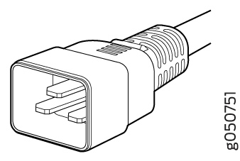
AC Power Cord Specifications for the MX304 Routers
A detachable AC power cord is supplied with the AC power supplies. The coupler is type C19 as described by International Electrotechnical Commission (IEC) standard 60320. The plug end of the power cord fits into the power source outlet that is standard for your geographical location.
Detachable AC power cords are shipped with the AC power supplies. Table 8 lists the default power cord that is provided for each country. The plug end of the power cord fits into the power source outlet that is standard for your geographical location.
The AC power cord provided with each power supply is intended for use with that power supply only and not for any other use.
In North America, AC power cords must not exceed 4.5 meters in length, to comply with National Electrical Code (NEC) Sections 400-8 (NFPA 75, 5-2.2) and 210-52 and Canadian Electrical Code (CEC) Section 4-010(3). The cords supplied with the switch are in compliance.
Table 8 gives the AC power cord specifications for the countries and regions listed in the table.
|
Country/Region |
Electrical Specifications |
Plug Standards |
Juniper Model Number |
Graphic |
|---|---|---|---|---|
|
Argentina |
250 VAC, 16 A, 50 Hz |
IRAM 2073 |
CBL-EX-PWR-C19-AR |
|
|
Australia |
250 VAC, 15 A, 50 Hz |
AS/NZS 3112 |
CBL-EX-PWR-C19-AU |
|
|
Brazil |
250 VAC, 16 A, 50 Hz |
NBR 14136 |
CBL-EX-PWR-C19-BR |
|
|
China |
250 VAC, 16 A, 50 Hz |
GB 2099 |
CBL-EX-PWR-C19-CH |
|
|
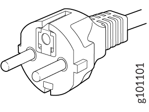
Europe (except Italy, Switzerland, and United Kingdom) |
250 VAC, 16 A, 50 Hz |
CEE (7) 7 |
CBL-EX-PWR-C19-EU |
|
|
India |
250 AC, 16 A, 50 Hz |
SABS 164/1:1992 Type ZA/3 |
CBL-EX-PWR-C19-SA |
|
|
Israel |
250 AC, 16 A, 50 Hz |
SI 32 |
CBL-EX-PWR-C19-IL |
|
|
Italy |
250 VAC, 16 A, 50 Hz |
CEI 23-16 |
CBL-EX-PWR-C19-IT |
|
|
Japan |
250 VAC, 15 A, 50 Hz or 60 Hz |
NEMA L6-20 |
CBL-PWR-C19-HT-JP |
 |
|
125 VAC, 15 A, 50 Hz or 60 Hz |
NEMA5-15Type N5/15 |
CBL-EX-PWR-C19-JP110V |
|
|
|
Korea |
250 VAC, 16 A, 50 Hz |
KC 8305 |
CBL-EX-PWR-C19-KR |
|
|
North America |
250 VAC, 16 A, 60 Hz |
NEMA 6-20 Type N6/20 |
CBL-EX-PWR-C19-US |
|
| 250 VAC, 16 A, 60 Hz |
NEMA L6-20P Type NEMA Locking |
CBL-EX-PWR-C19-USL |
|
|
|
South Africa |
250 VAC, 16 A, 50 Hz |
SABS 164-1 |
CBL-EX-PWR-C19-SA |
|
|
Switzerland |
250 VAC, 16 A, 50 Hz |
SEV 5934/2 (Type 23 16A plug) |
CBL-EX-PWR-C19-SZ |
|
|
United Kingdom |
250 VAC, 13 A, 50 Hz |
BS 1363(A) |
CBL-EX-PWR-C19-UK |
|
|
Worldwide (except Japan) |
250 VAC, 16 A, 50 Hz |
EN 60320-2-2/1 |
CBL-EX-PWR-C19-C20 |
|
See Also
DC Power Circuit Breaker Requirements for the MX304 Router
Each DC power supply has a single DC input (–48 VDC and return) that requires a dedicated circuit breaker. We recommend that you use a dedicated customer-site circuit breaker rated for 60 A (60 VDC), or as required by local code. Doing so enables you to operate the router in any configuration without upgrading the power infrastructure.
DC Power Cable Specifications for the MX304 Router
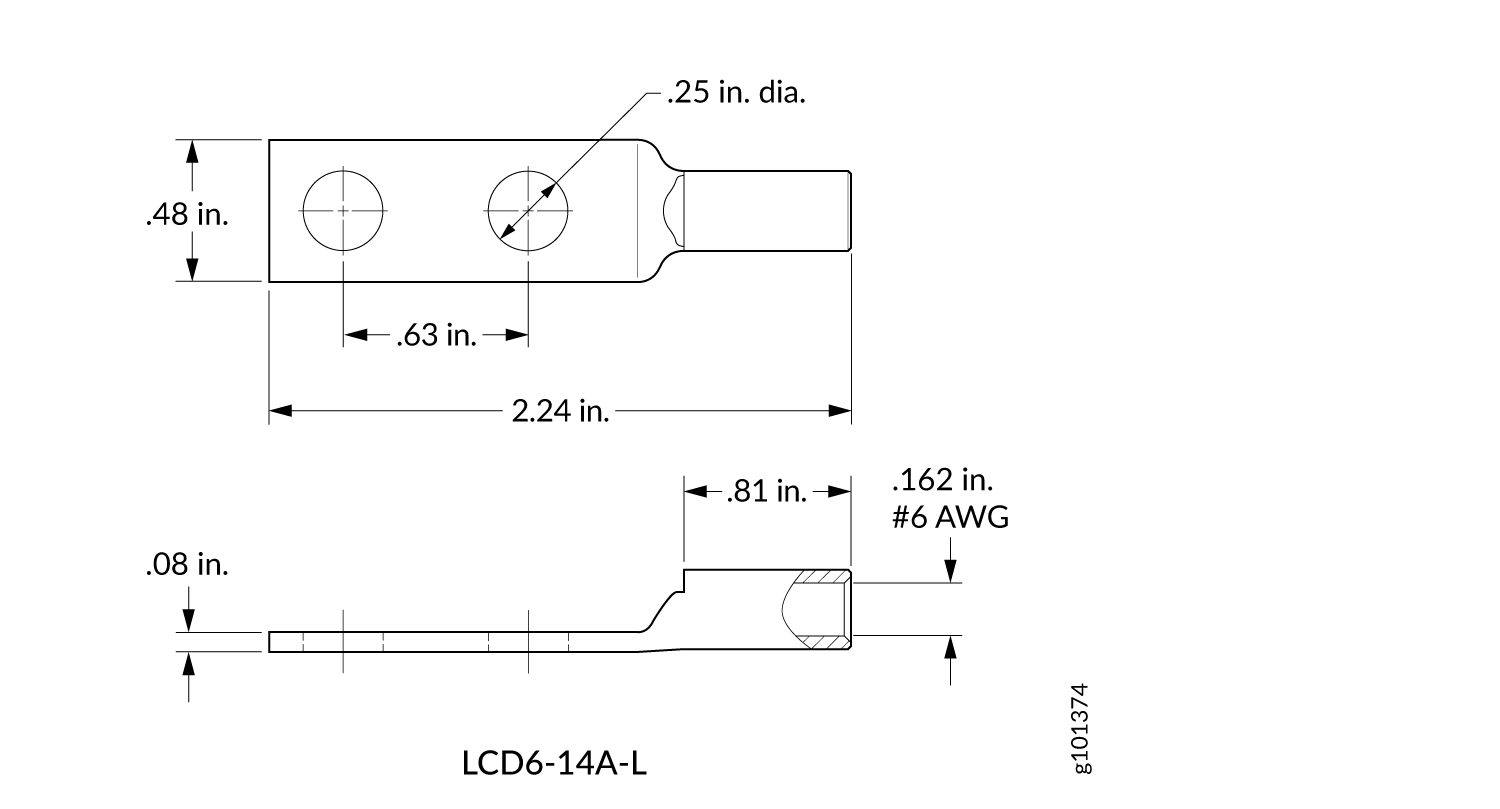
DC Power Cable Lug Specifications
The accessory box shipped with the router includes the cable lugs that attach to the terminal of each power supply.
The DC power cable lug is provided. The DC power lug accommodates #6 AWG (4.11 mm²) stranded wire. The grounding cable that you provide for the chassis must be the same size or heavier than the input wire of each power supply. Minimum recommendations are 6 AWG (4.11 mm²) stranded wire, minimum 60°C wire, or as permitted by local code.
Install heat-shrink tubing insulation around the power cables at the connection point of the DC power supply terminal.
Before you install the router, a licensed electrician must attach a cable lug to the grounding and power cables that you supply. A cable with an incorrectly attached lug can damage the router.
DC Power Cable Specifications
You must supply four DC power cables that meet the following specifications: 6 AWG (4.11 mm²) stranded wire,minimum 60°C wire, or as permitted by local code.
Install heat-shrink tubing insulation around the power cables at the connection point of the DC power supply terminal.
See Also
DC Power Source Cabling for MX304 Router
The DC power supply in PSM0 must be powered by a dedicated power feed derived from feed A, and the DC power supply in PSM1 must be powered by a dedicated power feed derived from feed B. This configuration provides the commonly deployed A/B feed redundancy for the system.
You must ensure that power connections maintain the proper polarity. The power source cables might be labeled (+) and (–) to indicate their polarity. There is no standard color coding for DC power cables. The color coding used by the external DC power source at your site determines the color coding for the leads on the power cables that attach to the terminal studs on each power supply.
For field-wiring connections, use copper conductors only.
Power cords and cables must not block access to device components or drape where people could trip on them.
See Also
High-Voltage (AC/DC) Power Cable Specifications for the MX304
One end of the cable has an Anderson APP-400 connector, the other end of the cable is bare wire. See Table 9 . These cables are separately orderable and are not shipped automatically with power supply orders. An example of the right-angle cable and connector is shown in Figure 3 .
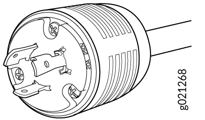
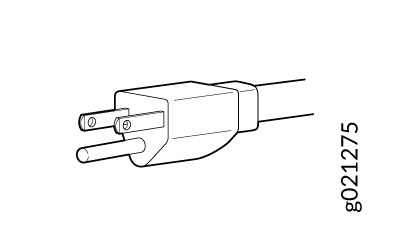
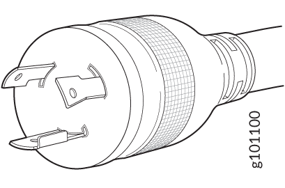
For connection to AC systems, Juniper provides a cable with either a NEMA I7-20P connector (see Figure 2).
|
Locale |
Cord Set Rating |
Connector |
Spare Juniper Model Number |
|
|---|---|---|---|---|
|
HVDC power cord |
Any |
30- A, 400 VAC |
Anderson/straight to bare wire |
CBL-PWR2-BARE |
|
HVAC power cord |
North America | 20 A, 277 V | NEMA I7-20P | CBL-JNP-SG4-HVAC |
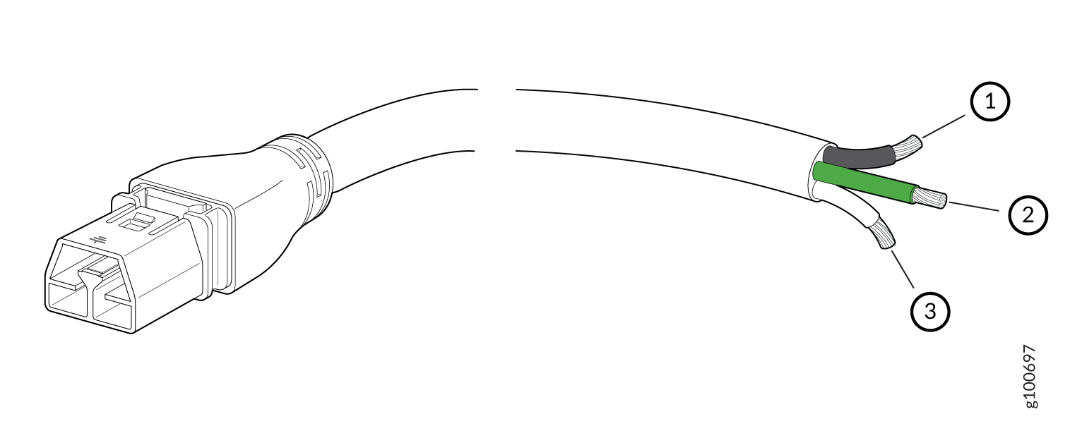
1 — Black wire–Return (+) | 3 — White wire–Neutral |
2 — Green wire-Ground |