Help us improve your experience.

Let us know what you think.

Do you have time for a two-minute survey?


Replacing an MX2010 DC Power Distribution Module Cable

Disconnecting an MX2010 DC Power Distribution Module Cable

Warning:

Before performing DC power procedures, disconnect all power sources. To ensure that all power is off, locate the circuit breaker on the panel board that services the DC circuit, switch the circuit breaker to the OFF position, and tape the switch handle of the circuit breaker in the OFF position.

To disconnect a power cable for a DC PDM:

  1. Switch off the dedicated customer-site circuit breaker for the PDM being removed. Follow your site's procedures for ESD.
  2. Make sure that the voltage across the DC power source cable leads is 0 V and that there is no chance that the cables might become active during the removal process.
  3. Verify that the –48V LED on the PDM is not lit.
  4. Remove the power cable from the external DC power source.
  5. Attach an electrostatic discharge (ESD) grounding strap to your bare wrist, and connect the strap to one of the ESD points on the chassis.
  6. Remove the clear plastic cover protecting the terminal studs on the faceplate.
  7. Remove the nut and washers from each of the terminal studs. (Use a 7/16-in. [11 mm] nut driver or socket wrench.)
    Note:

    The input positions for the RTN (return) DC terminal studs and the -48V (input) DC terminal studs correspond to the DC Power Supply Module (PSM) directly above and below. The DC PSM slot positions are labeled, but the DC PDM cable positions that correlate to the PSM positions are not labeled.

  8. Remove the cable lug from the terminal studs.
  9. Carefully move the power cable out of the way.
  10. Replace the clear plastic cover protecting the terminal studs on the faceplate.

Connecting an MX2010 DC Power Distribution Module Cable

Warning:

Before performing DC power procedures, disconnect all power sources. To ensure that all power is off, locate the circuit breaker on the panel board that services the DC circuit, switch the circuit breaker to the OFF position, and tape the switch handle of the circuit breaker in the OFF position.

To connect a power cable for a DC PDM:

  1. Locate a replacement power cable that meets the specifications defined in MX2010 DC Power (-48 V) System Electrical Specifications.
  2. Verify that a licensed electrician has attached a cable lug to the replacement power cable.
  3. Verify that the –48V LED is off.
    Note:

    The input positions for the RTN (return) DC terminal studs and the -48V (input) DC terminal studs correspond to the DC Power Supply Module (PSM) directly above and below. The DC PSM slot positions are labeled, but the DC PDM cable positions that correlate to the PSM positions are not labeled.

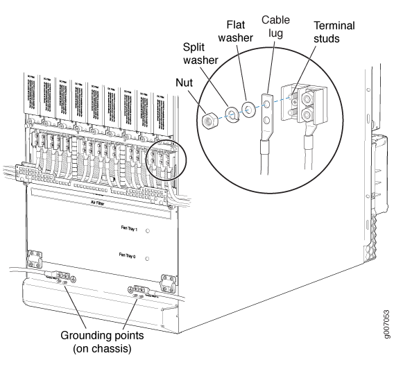
  4. Secure the power cable lug to the terminal studs, first with the flat washer, then with the split washer, and finally with the nut. Apply between 23 lb-in. (2.6 Nm) and 25 lb-in. (2.8 Nm) of torque to each nut (see Figure 1). Do not overtighten the nut. (Use a 7/16-in. [11 mm)] torque-controlled driver or socket wrench.)
    CAUTION:

    Ensure that each power cable lug seats flush against the surface of the terminal block as you are tightening the nuts. Ensure that each nut is properly threaded onto the terminal stud. The nut should be able to spin freely with your fingers when it is first placed onto the terminal stud. Applying installation torque to the nut when the nut is improperly threaded might result in damage to the terminal stud.

    CAUTION:

    The maximum torque rating of the terminal studs on the DC PDM is 25 lb-in. (33.89 Nm). The terminal studs might be damaged if excessive torque is applied. Use only a torque-controlled driver or socket wrench to tighten nuts on the DC PDM terminal studs.

    Figure 1: Connecting Power Cables to the DC Power Distribution ModuleConnecting Power Cables to the DC Power Distribution Module
  5. Route the positive and negative DC power cables through the plastic cable restraint cover. Make sure that the cable does not touch or obstruct any router components.
  6. Verify that the DC power cable is connected correctly, that it does not touch or block access to router components, and that it does not drape where people could trip on it.
  7. Attach the power cable to the DC power source.
  8. Turn on the dedicated customer-site circuit breaker to the PDM.
  9. Verify that the –48V LED on the PDM is lit steadily.
  10. On each of the DC power input sources, switch the DC circuit breaker to the center position before moving it to the ON position.
    Note:

    The circuit breaker might bounce back to the OFF position if you move the breaker too quickly.

    Observe the status LEDs on the PDM faceplate. If the PDM is correctly installed and functioning normally, the –48V LEDs light green steadily.